Table of Contents
Advertisement
Quick Links
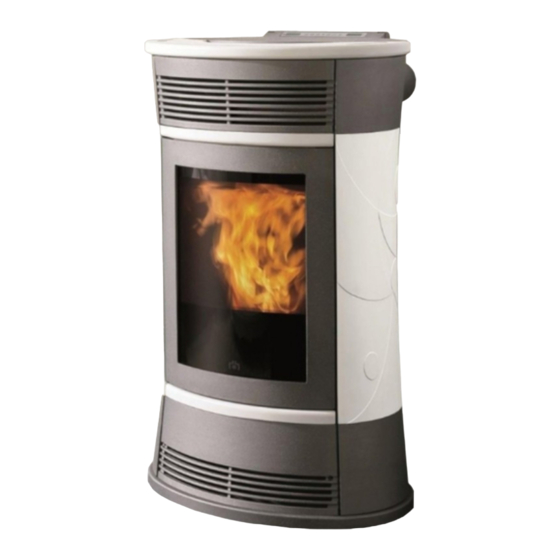
CHERIE - FUNNY - MOON
I
Installazione, uso e manutenzione
UK
Installation, use and maintenance
F
Installation, usage et maintenance
E
Instalación, uso y mantenimiento
D
Installations-, Betriebs- und Wartungsanleitung
NL
Installatie, gebruik en onderhoud
Simpaty Line
SPACE - VINTAGE
p. 2
p. 33
p. 64
p. 95
p. 126
p. 157
Advertisement
Table of Contents

Related Manuals for EdilKamin Simpaty Cherie


Summary of Contents for EdilKamin Simpaty Cherie
- Page 1 Simpaty Line CHERIE - FUNNY - MOON SPACE - VINTAGE Installazione, uso e manutenzione p. 2 Installation, use and maintenance p. 33 Installation, usage et maintenance p. 64 Instalación, uso y mantenimiento p. 95 Installations-, Betriebs- und Wartungsanleitung p. 126 Installatie, gebruik en onderhoud p.
- Page 2 - All images are for illustration purposes only; actual products may vary. DECLARATION OF CONFORMITY The undersigned EDILKAMIN S.p.a. with head office headquarters at Via Vincenzo Monti 47 - 20123 Milan - Italy - VAT IT00192220192 Declares under its own responsability as follows:...
-
Page 3: Principle Of Operation
• The glass can be cleaned when COLD with a suitable pro- The main functions can also be controlled by remote control. duct (e.g. GlassKamin Edilkamin) and a cloth. A serial port is found at the back of the stove (optional cable: code 621240) to be connected to devices that allow remote •... - Page 4 FEATURES Remote control to manage Reserve warning that indica- ignition, shutdown, automatic Multifunctional top with a synoptic tes when a whole sack of pel- and manual operation from a panel to set the desired temperature and lets can be loaded. distance.
-
Page 5: Electronic Circuit Board
FEATURES Pellet stoves are equipped with the LEONARDO SYSTEM. ® LEONARDO ® is a combustion safety and control system which allows optimal performance in all conditions. LEONARDO ® ensures excellent operation thanks to two sensors measuring the pressure level in the combustion cham- ber and smoke temperature. - Page 6 DIMENSIONS CHERIE - FUNNY - MOON - SPACE Hot air channel 16,5 16,5 16.5 16.5 Ø 100 mm Serial socket Rs232 fitting Combustion air Ø 40 mm Smoke outlet Ø 80 mm VINTAGE Hot air channel Ø 100 mm Serial socket Rs232 fitting...
-
Page 7: Electrical Characteristics
It is also important to consider the position of the stove in the room to be heated. The data shown above is purely indicative. EDILKAMIN s.p.a. reserves the right to make changes to these pro- ducts to improve their performance with no prior warning. - Page 8 COVERING INSTALLATION CHERIE For proper assembly of the ceramics series on the stove, Phase A proceed as indicated in the sequence (the number in brackets refers to the exploded view of the stove): Phase A This phase presents the stove after being unpacked and positioned in the room.
- Page 9 COVERING INSTALLATION CHERIE Phase C Phase C left side ceramic panel assembly: Fig. 5 13) Keep the hearth door closed 14) Align the apertures present on the front part of the ceramic panel (47) to the fastening brackets (44) located on the structure (fig.
- Page 10 CHERIE COVERING DISASSEMBLY For proper disassembly of the ceramic series proceed as Phase A follows: Phase A Represents the stove in its finished version Phase B Remove the ceramic top (1). Phase C/D Phase B Disassembling the ceramic front plates: Disassemble the upper grille (2) applying suitable pres- sure to unhook it from the locking springs.
- Page 11 COVERING INSTALLATION FUNNY Phase A Phase A This phase presents the stove after being unpacked and positioned in the room Phase B Remove the upper front panel "D" (69) which is fitted into place, then assemble the ceramic front panel "E" (53) to the upper front panel (69) with screws (71) sup- plied, then reposition.
- Page 12 COVERING INSTALLATION MOON/SPACE Phase A Phase A Phase B This phase presents the stove after being unpacked and positioned in the room Phase B Remove the front panel (69) to remove the two screws holding the upper right (51) and left (49) cast iron front panels Phase C/D Assemble the plates (140) to the stone sides "A-B"...
- Page 13 COVERING INSTALLATION VINTAGE Phase A Phase A This phase presents the stove after being unpacked and positioned in the room Phase B Remove, pulling outwards, the upper front grille (1) and the lower front panel (2), assembled in an interlocking manner on the stove.
- Page 14 COVERING INSTALLATION VINTAGE Phase E Phase E Installation of the ceramic intermediate side compo- nents Place the ceramic component parallely along the side, fitting the housings 8 (at the ends of the front edge) into the fastening brackets (6). Slide the ceramic component towards the rear of the stove until it fits completely on the brackets.
-
Page 15: Installation
An inadequate earthing system can cause anomalies If the smoke channel is fitted inside a chimney flue, the latter must for which Edilkamin cannot be held liable. be suitable for solid fuel. If it is wider than 150 mm in diameter it... -
Page 16: Hot Air Circulation
INSTALLATION HOT AIR CIRCULATION fig. B In the installation area, the hot air is emitted through the grill installed in the upper front portion (fig. E). To channel the hot air in one or two adjoining rooms, the stove is equipped with two pipes on the back (fig.A), to which special aluminium pipes must be connected. - Page 17 INSTALLATION Examples of channelling Hot air channelling in adjacent rooms 100% 100% Hot air in the room where the stove is installed via a front grille 100%...
- Page 18 INSTALLATION 1st SOLUTION: KIT 10 (code 643890) - ADJACENT ROOM ONLY Note: THE PIPES ON THE HOT AIR OUTLETS MUST BE FITTED BEFORE APPLYING THE COVE- RINGS AND PRIOR TO DISASSEMBLY OF THE UPPER CAST IRON SIDE FLANK. THE FIRST PART OF THE FLEXIBLE PIPE MUST BE COMPLETELY "RELAXED"...
- Page 19 INSTALLATION 2nd SOLUTION: KIT 10 BIS (code 645690) - NON-ADJACENT ROOM ONLY Note: THE PIPES ON THE HOT AIR OUTLETS MUST BE FITTED BEFORE APPLYING THE COVE- RINGS AND PRIOR TO DISASSEMBLY OF THE UPPER CAST IRON SIDE FLANK. THE FIRST PART OF THE FLEXIBLE PIPE MUST BE COMPLETELY "RELAXED"...
- Page 20 INSTALLATION 3rd SOLUTION: KIT 10 (code 643890) con KIT 10 BIS (code 645690) - BOTH ROOMS Note: THE PIPES ON THE HOT AIR OUTLETS MUST BE FITTED BEFORE APPLYING THE COVE- RINGS AND PRIOR TO DISASSEMBLY OF THE UPPER CAST IRON SIDE FLANK. THE FIRST PART OF THE FLEXIBLE PIPE MUST BE COMPLETELY "RELAXED"...
-
Page 21: Mimic Panel
INSTRUCTIONS FOR USE MIMIC PANEL hold down for 2 seconds to turn stove on or off opens the menu increases/decreases the various settings (pellet load/reserve key) pressed once it tells the stove that a 15 kg. sack of pellets has been loaded, enabling the reserve to be monitored (see following page 55) RH knob: to adjust ventilation (from 1 to 10) LH knob: to adjust power (from 1 to 5) - Page 22 For the stove to function properly, you MUST NOT burn anything else in it. Using other materials (including wood) will render the warranty null and void. Such use is detected by laboratory analyses. Edilkamin has designed, tested and programmed their stoves to guarantee the best performance when pellets with the following characteristics are used: diameter: 6 millimetres - maximum length: 40 mm - maximum moisture content: 8% - calorific value: at least 4300 kcal/kg.
- Page 23 INSTRUCTIONS FOR USE Manual mode from synoptic panel/remote control Weekly timer (optional) Press the MENU button on the remote control for 2 With the stove in operation mode or on standby, press and seconds to access the time setting function and press the release the MENU button on the synoptic panel/remote + key to control and ‘Power’...
- Page 24 INSTRUCTIONS FOR USE Pellet reserve warning Stoves are equipped with an electronic pellet detection system. The detection system is integrated into the electronic control board, allowing the stove to monitor how many kilos of pellets are left. This verification is implemented at any point whilst the stove is in operation mode.
- Page 25 INSTRUCTIONS FOR USE REMOTE CONTROL cod. 633310 : ignition / shutdown button (press for approximately 1 second) this button can also be pressed to exit the programming menu button to increase the power/operating temperature (when inside a menu, it increases the displayed variable) button to decrease the power/operating temperature (when inside a menu, it decreases the displayed variable)
-
Page 26: Selecting The Operating Mode
INSTRUCTIONS FOR USE TEMPERATURE DETECTED BY THE REMOTE CONTROL The remote control is equipped with an internal sensor to detect the room temperature and display it in real time. The detected temperature is transmitted periodically to the control board of the insert/stove if the transmission LED of the remote control and the receiving sensor of the synoptic panel of the insert/stove are in each other's field of view. -
Page 27: Low Battery Indicator
INSTRUCTIONS FOR USE LOW BATTERY INDICATOR When the battery icon lights up it indicates that the batteries inside the remote control are almost flat. Replace them with three new batteries of the same model (size AAA 1.5V). - Do not use new batteries with used ones. - Do not mix brands and different types as every type and brand has a different capacity. -
Page 28: Possible Troubleshooting
POSSIBLE TROUBLESHOOTING PROBLEM CAUSE SOLUTIONS check that the power cable is synoptic panel is off no mains voltage connected; check the fuse (on power socket, page 36) too far from stove move closer to the stove remote control (optional) not working check the battery and if necessary, remote control battery flat replace it... - Page 29 POSSIBLE TROUBLESHOOTING 4) Block_FI/NO Start (intervenes if the flame fails to appear within a maximum of 15 minutes, or if the ignition tem- peratuse is not reached). Shuts down due to incorrect smoke temperature during ignition. Distinguish either of the following cases: The flame has appeared but after Ignition appears on The flame has NOT appeared...
-
Page 30: Daily Maintenance
MAINTENANCE Before performing any maintenance, disconnect the appliance from the mains. Regular maintenance is required for the stove to function correctly. FAILURE TO PERFORM REGULAR MAINTENANCE, at least on a SEASONAL basis, could lead to poor functionality. Any problems resulting from lack of maintenance will immediately void the warranty. DAILY MAINTENANCE Operations must be performed when the stove is off, cold and unplugged from the power supply Cleaning must be carried out with a vacuum cleaner. -
Page 31: Seasonal Maintenance
MAINTENANCE Cleaning the smoke duct With the stove off and cold, remove the lower cast iron front panel (1), removing the 2 screws (fig D), move the clea- • ning rods (2) with force (fig E), the 4 silicone caps * (fig E), then suction residue. The amount of residue will depend on the type of fuel and system. -
Page 32: Optional Extras
CHECK LIST To be integrated with a complete reading of the technical specifications Positioning and installing • Commissioned by a qualified DEALER who has issued the warranty and maintenance manual • Room ventilation • Only the stove outlet passes through the smoke channel/chimney flue •...
Need help?
Do you have a question about the Simpaty Cherie and is the answer not in the manual?
Questions and answers