Advertisement
Quick Links
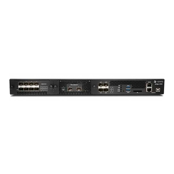
vEdge 2000 Router
The vEdge 2000 router delivers highly secure site-to-site data connectivity to large enterprises, offers interface
modularity, and provides the following features:
• 1RU, standard rack mountable in a 19-inch rack
• Support for AC input power
• Four built-in 1-Gigabit Ethernet SFP ports (4x1-Gigabit Ethernet)
• Two Pluggable Interface Module (PIM) slots that support two types of PIMs:
• Eight ports of 1-Gigabit Ethernet (8x1-Gigabit Ethernet)
• Two ports of 10-Gigabit Ethernet (2x10-Gigabit Ethernet)
• Encryption and QoS support
• 10-Gbps forwarding throughput (inclusive of encryption)
• Secure identification chip for anti-counterfeit and secure authentication
• Redundant hot-swappable fan tray modules
• Dual redundant hot-swappable power supply slots
• Front to back cooling
Chassis Views
Figure 1 and Figure 2 show the front and back panels of the vEdge 2000 router, indicating the location of the
power interfaces, module slots, status indicators, and chassis identification labels.
Figure 1: Front Panel of the vEdge 2000 Router
vEdge 2000 Router
1
Advertisement

Related Manuals for Viptela vEdge 2000

Summary of Contents for Viptela vEdge 2000
- Page 1 • Front to back cooling Chassis Views Figure 1 and Figure 2 show the front and back panels of the vEdge 2000 router, indicating the location of the power interfaces, module slots, status indicators, and chassis identification labels. Figure 1: Front Panel of the vEdge 2000 Router...
-
Page 2: Declaration Of Conformity
Exception ENC. As such, they are eligible for export according to Section 740.17 of the EAR. The Viptela solutions and products can be delivered to most end users worldwide, except to entities or end users in the following countries: Cuba, Iran, North Korea, Sudan, and Syria. -
Page 3: Components And Specifications
For additional information on controlled technologies, please contact Viptela support at support@viptela.com Components and Specifications This article provides the chassis specifications of the vEdge 2000 router and lists the other router components. Chassis Specifications Table 1 lists the specifications for the vEdge 2000 router chassis. - Page 4 2000 Router Components and Specifications Item Specification 100-240 Volts AC input voltage AC input line frequency 50-60 Hz Typical power consumption 125 Watts Physical Specifications Chassis height 1.75 in. (4.45 cm) Chassis width Chassis only: 17.25 in. (43.82 cm) Chassis with mounting brackets attached: 19 in.
- Page 5 Front Panel Components This article describes the LEDs, reset button, and the SD card slot on the front panel of the vEdge 2000 router. See At a Glance for the exact location of these components on the front panel of the router.
- Page 6 Reset Button The front panel of the vEdge 2000 router has a reset button. The reset button is recessed to avoid accidentally pressing it while the router is operational. To press the reset button, use a sharp narrow tool. Table 2 describes the effects of pressing the reset button.
- Page 7 PIM and Transceiver Modules SD Card Slot The front panel of the vEdge 2000 router has an SD card slot. The SD card slot has the following specifications: • High speed bus: maximum 25 MB/second • Supported card types: SD, SDHC...
- Page 8 Combinations for the vEdge 2000 Router below. Interface Port Combinations for the vEdge 2000 Router A vEdge 2000 router has four fixed 1-Gigabit Ethernet interfaces, and you can install one or two PIM modules for additional interfaces. You can combine the fixed interfaces and the PIM modules as follows: •...
- Page 9 Changing PIM Types If you change the type of PIM that is installed in a vEdge 2000 router slot from a 1-Gigabit Ethernet to a 10-Gigabit Ethernet PIM, or vice versa, possibly as part of an RMA process, follow these steps: 1.
- Page 10 2000 Router PIM and Transceiver Modules Table 6: Ethernet Standard Specification Value 1000 BASE-T Model Number SFP-1GE-Base-T Rate 10/100/1000 Mbps Connector Type RJ-45 Fiber Count Transmitter Wavelength Minimum Launch Power Maximum Launch Power Minimum Receiver Sensitivity Maximum Input Power...
- Page 11 2000 Router PIM and Transceiver Modules Ethernet Standard Specification Value Rate 1000 Mbps Connector Type Fiber Count Dual Transmitter Wavelength 1310 nm Minimum Launch Power -9.5 dBm Maximum Launch Power -3 dBm Minimum Receiver -25 dBm Sensitivity Maximum Input Power...
- Page 12 2000 Router PIM and Transceiver Modules Ethernet Standard Specification Value Rate 10 Gbps Connector Type Fiber Count Dual Transmitter Wavelength 850 nm Minimum Launch Power -7.3 dBm Maximum Launch Power -1 dBm Minimum Receiver -9.9 dBm Sensitivity Maximum Input Power...
-
Page 13: Supported Transceivers
This article provides a list of copper and fiber transceivers that have been tested and qualified for use in vEdge 1000 and vEdge 2000 routers. You can order the transceivers that have a Viptela part number in the tables below directly from Viptela. - Page 14 2000 Router Supported Transceivers Table 9: Manufacturer & Part Viptela Part vEdge vEdge vEdge5000 Description Number Number 1000 2000 Router Router Router Avago • Small form-factor pluggable (SFP) AFBR-5710PZ transceiver • LC-type connector • Short-reach 850-nm optics over multimode fiber for 1-Gbps...
-
Page 15: Ports And Connectors
Network Ports (SFP Ports) The built-in network ports on the vEdge 2000 router as well as the 8x1-Gigabit Ethernet SFP PIM module support 1-Gbps SFP module. The 2x10-Gigabit Ethernet SFP+ PIM module supports 10-Gbps SFP+ module. Table 1 provides the pinout information for the built-in SFP and the PIM SFP/SFP+ port connector. The SFP/SFP+ ports comply with the SFP/SFP+ MSA standards. - Page 16 Module transmitter ground Network Port LEDs Each network port on the vEdge 2000 router has two LEDs—the link/activity/status LED and the LAN/WAN LED. See Figures 1 through 3. Figure 1: LEDs on the Built-in SFP Network Ports on a vEdge 2000 Router...
- Page 17 2000 Router Ports and Connectors Figure 2: LEDs on the Network Ports on an 8x1GE SFP PIM Figure 3: LEDs on the Network Ports on a 2x10GE SFP+ PIM vEdge 2000 Router...
- Page 18 2000 Router Ports and Connectors Table 11: Color State & Description • Blinking The link is negotiated and active at maximum speed, and Green there is link activity. • On steadily The link is negotiated and active at maximum speed, but there is no link activity.
- Page 19 Ports and Connectors Management Port The management port on a vEdge 2000 router uses an RJ-45 connector to connect to a management device for out-of-band management. The management port uses an autosensing RJ-45 connector to support a 10/100/1000Base-T connection. The two LEDs on the port indicate link/activity on the port and the administrative status of the port.
- Page 20 • Off—Link is not up Console Port The console port on a vEdge 2000 router is accessible via the following external interfaces: • An RS-232 serial interface that uses an RJ-45 connector to connect to a console management device. • A USB serial interface that uses a standard USB Type B connector to connect to a console management device.
- Page 21 PC or a laptop. If your PC or laptop does not have a DB-9 male connector pin and you want to connect your PC or laptop to a vEdge 2000 router, use a combination of the RJ-45-to-DB-9 female adapter along with a USB-to-DB-9 male adapter.
-
Page 22: Field-Replaceable Units
Signal You can also connect the vEdge 2000 router to a management device such as a PC or a laptop using an RJ-45-to-RJ45 cable as shown in Figure 7. Note that the vEdge 2000 router does not ship with an RJ-45-to-RJ-45 cable. - Page 23 Power Supply and Cooling in Cisco vEdge 2000 Routers The vEdge 2000 router ships with two AC power supplies installed. Read this article to learn more about the AC power supply in the router as well as about the cooling system and airflow through the router chassis.
- Page 24 AC Power Cord Specifications The vEdge 2000 router ships with a detachable AC power cord. The power cord has a C13 connector at one end and the other end is specific to the country/locality to which the product is shipped.
-
Page 25: Planning And Installation
If the temperature inside the chassis rises above the maximum threshold temperature, the router shuts down automatically. Planning and Installation This article provides general safety standards to adhere to when installing or connecting a vEdge 2000 router or its components. General Safety Standards •... -
Page 26: Prepare For Router Installation
This article provide guidelines and requirements for preparing your site to install the vEdge 2000 router. Site Preparation Guidelines Efficient operation of your vEdge 2000 router requires proper site planning and proper layout of your equipment rack or wiring closet: •... - Page 27 • High humidity conditions can cause moisture to penetrate into the chassis. The device supports 10% to 85% humidity levels, non-condensing. Rack Requirements You can mount the vEdge 2000 router in a two-post or a four-post rack. Table 1 provides the rack requirements for the router. Table 20:...
- Page 28 4. Take out the router and each accessory. 5. Verify the router components against the packing list included in the box. Figure 1: Unpacking the vEdge 2000 Router Note: It is recommended that you do not discard the shipping carton and packing material when you unpack the router.
- Page 29 Screws for sliders (D) Screws for locking 1U sliders (E) vEdge 2000 Router Quick Start Mount the vEdge 2000 Router in a Rack You can mount the vEdge 2000 router in a 19-inch rack in one of the following ways: vEdge 2000 Router...
- Page 30 • Mount the router on all four posts • Mount the router on two mid-posts In addition to the accessory box, you need the following tools to mount a vEdge 2000 router in a 19-inch rack: • Number 2 Phillips (+) screwdriver •...
- Page 31 Tip: It is recommended that you retain the dust covers in any unused ports. Mount the vEdge 2000 Router on Four Posts To mount a vEdge 2000 router on four posts in a 19-inch rack: 1. Place the router chassis on the floor or on a sturdy table near the rack.
- Page 32 (four on each side) in the packet marked B. Figure 5: Attaching the Short Mounting Ears to the vEdge 2000 Router Chassis 1. Slide out the two interchangeable 1U sliders, and secure to either side of the router chassis using the eight screws for sliders (four on each side) in the packet marked D.
- Page 33 2000 Router Install the vEdge 2000 Router Figure 7: Positioning the vEdge 2000 Router in the Rack 1. Have a second person secure the mounting ears to the front of the rack using four rack-mount screws (two on each side) from the packet marked A. Tighten the screws.
- Page 34 Warning: To prevent bodily injury when mounting or servicing the vEdge 2000 router in a rack, you must take special precautions to ensure that the system remains stable. The following guidelines are provided to ensure your safety: •...
- Page 35 Install the vEdge 2000 Router Mount the vEdge 2000 Router on Mid-Posts To mount a vEdge 2000 router on two mid-posts in a 19-inch rack: 1. Place the router chassis on the floor or on a sturdy table near the rack.
- Page 36 Step 1: Connect Earth Ground to the Router To meet safety and electromagnetic interference (EMI) requirements and to ensure proper operation of the vEdge 2000 router, connect the router to earth ground before you power it on. To do so, you need the following tools: •...
- Page 37 Install an AC Power Supply in a vEdge 2000 Router The AC power supply in a vEdge 2000 router is a hot-insertable and hot-removable field replacement unit (FRU). You can remove and replace the power supply without powering off the router or disrupting normal functioning.
- Page 38 Install a Fan Tray in a vEdge 2000 Router The vEdge 2000 router contains four individual fan trays, each comprising a double-stacked fan module. The fan tray is a hot-insertable and hot-removable field-replaceable unit (FRU). You can remove and replace an individual fan tray without powering off the router or disrupting normal functioning.
- Page 39 1. Using both hands, place the PIM in the empty slot and slide it in gently until it is fully seated. Figure 4: Installing a PIM in a vEdge 2000 Router 1. Tighten the captive thumb screws using the number 2 Phillips (+) screwdriver.
- Page 40 2000 Router Default Configuration Install a Transceiver in a vEdge 2000 Router The transceivers for the vEdge 2000 router are hot-removable and hot-insertable field-replaceable units (FRUs). You can remove and replace them without powering off the router or disrupting router functions.
-
Page 41: Maintenance And Troubleshooting
512 interface mgmt0 ip address 192.168.1.1/24 no shutdown Maintenance and Troubleshooting Now that you have installed and connected the vEdge 2000 router, you can monitor and troubleshoot the various LEDs and system alarms on the router. vEdge 2000 Router... - Page 42 Hardware Alarms Hardware alarms on the vEdge 2000 router are predefined and are triggered by a physical condition on the router such as a power supply failure, excessive component temperature, or fan failure. The vEdge 2000 router triggers the following types of hardware alarms: •...
- Page 43 LEDs The chassis LEDs located on the front panel of the vEdge 2000 router indicate the status of the router. If there are one or more major alarms active in the router, the SYS LED is lit red. If there are one or more minor alarms active in the router, the SYS LED is lit amber.
- Page 44 Remove an AC Power Supply from a vEdge 2000 Router The AC power supply in a vEdge 2000 router is a hot-insertable and hot-removable field replacement unit (FRU). You can remove and replace the power supply without powering off the router or disrupting normal functioning.
- Page 45 Remove a Fan Tray from a vEdge 2000 Router The vEdge 2000 router contains four individual fan trays each comprising of a double-stacked fan module. The fan tray is a hot-insertable and hot-removable field-replaceable unit (FRU). You can remove and replace an individual fan tray without powering off the router or disrupting normal functioning.
- Page 46 See Front Panel of the vEdge 2000 Router . To remove a PIM from a PIM slot in a vEdge 2000 router, you need the following parts and tools: • Number 2 Phillips (+) screwdriver •...
- Page 47 The transceivers for the vEdge router are hot-removable and hot-insertable field-replaceable units (FRUs): You can remove and replace them without powering off the router or disrupting router functions. To remove any type of transceiver from a vEdge 2000 router, you need the following parts and tools: • A transceiver slot dust cover •...
- Page 48 If you are not installing a new transceiver, place the transceiver slot dust cover over the empty port. Figure 4: Removing a Transceiver from a vEdge 2000 Router Note: It is recommended that you purchase the optical transceivers and optical connectors for your vEdge routers from Viptela.
-
Page 49: Return Hardware
This article describes how to return a vEdge router or a hardware component to Viptela for repair or replacement. Locate Serial and Model Number To return a vEdge router or a hardware component to Viptela, you need the serial and model number of the router or the component being returned. - Page 50 1. If you do not have a vEdge 1000 router, skip this step. Otherwise: a. If the router is installed in a rack using the rack-mount kit from Viptela, remove the front stopper screwed along the front side of the rack-mount tray.
- Page 51 2000 Router Return Hardware 2. Place the router chassis in the plastic packing bag. 3. Place the side packing foam on both sides of the router chassis. 4. Secure the chassis in the cardboard carton. 5. Secure the top of the chassis by placing the top packing foam over the top of the chassis.
- Page 52 2000 Router Return Hardware vEdge 2000 Router...
Need help?
Do you have a question about the vEdge 2000 and is the answer not in the manual?
Questions and answers