Protec Algo-Tec 6500 User Manual
Interactive addressable fire control system
Hide thumbs
Also See for Algo-Tec 6500:
- Commissioning manual (57 pages) ,
- Commissioning manual (40 pages) ,
- Installation manual (28 pages)
Table of Contents

Related Manuals for Protec Algo-Tec 6500


Summary of Contents for Protec Algo-Tec 6500
- Page 1 Algo-Tec™ 6500/6600 INTERACTIVE ADDRESSABLE FIRE CONTROL SYSTEM (1-4 LOOPS) USER MANUAL Protec Fire Detection plc, Protec House, Churchill Way, Nelson, Lancashire, BB9 6RT, ENGLAND +44 (0) 1282 717171 www.protec.co.uk sales@protec.co.uk...
-
Page 2: Document Revision Details
Weekly Test section removed Notice This manual may be revised as a result of enhancements to the system software or hardware. Check for revisions to this manual, and download them, from the website www.protec.co.uk RDM0001/3_2 Page 2 of 70 © 2015 - 2017 Protec Fire Detection plc... -
Page 3: Table Of Contents
Table of Contents DOCUMENT REVISION DETAILS ......................2 INTRODUCTION ............................6 PROTEC MANUFACTURED ALGO-TEC™ 6000 EQUIPMENT 5 YEAR WARRANTY ........7 USER RESPONSIBILITIES ....................... 8 Requirements of the Premises Management Named Person ............... 8 ROUTINE TESTING OF THE SYSTEM ....................9 Daily Inspection ............................ - Page 4 Disable all alarm outputs ........................46 13.19 Disable all control outputs ........................46 13.20 Disable all non-fire outputs......................... 46 13.21 Settings ..............................47 13.22 Set Time / Date ............................48 RDM0001/3_2 Page 4 of 70 © 2015 - 2017 Protec Fire Detection plc...
- Page 5 Tools menu ............................62 14.3 Loop Tools ............................. 62 14.4 Exchange Device Menu ........................63 15.0 APPENDIX A, RVAV DESCRIPTION ..................68 16.0 STANDARDS, DIRECTIVES AND REGULATIONS INFORMATION..........69 RDM0001/3_2 Page 5 of 70 © 2015 - 2017 Protec Fire Detection plc...
-
Page 6: Introduction
Introduction This manual applies to the Protec 6500 and 6600 fire alarm control panels however for convenience; reference will be made only to the ‘6500’. Everything in this manual applies to both the 6500 and 6600 unless stated otherwise. The Protec 6500 Fire Alarm Control Panel has been designed and manufactured in the United Kingdom and complies fully with the latest standards dictating fire alarm system design practice (EN54-2:1997 + A1:2006 and EN54-4:1997 + A1:2002 + A2:2006). -
Page 7: Protec Manufactured Algo-Tec™ 6000 Equipment 5 Year Warranty
Protec Manufactured Algo-Tec™ 6000 Equipment 5 year warranty To demonstrate confidence in our product, we provide an extended warranty on our Protec manufactured Algo-Tec 6000 equipment. When a Protec maintenance contract is in place, we warrant all the Protec Algo-Tec 6000 equipment we manufacture for 5 years. -
Page 8: User Responsibilities
Ensure that, where necessary, a suitable zone plan is displayed and kept up to date. • Ensure that any relevant spare parts for system maintenance are held within the • premises. RDM0001/3_2 Page 8 of 70 © 2015 - 2017 Protec Fire Detection plc... -
Page 9: Routine Testing Of The System
Note:- Care is necessary to ensure that any person undertaking these tasks is competent to do so safely and has the relevent technical knowledge and training RDM0001/3_2 Page 9 of 70 © 2015 - 2017 Protec Fire Detection plc... -
Page 10: Access Levels
To enter access level 3a enter the level 3a code using the touchscreen LCD (section 12.8). Refer to sections 13 & 14 for the features accessible at access level 3a. RDM0001/3_2 Page 10 of 70 © 2015 - 2017 Protec Fire Detection plc... -
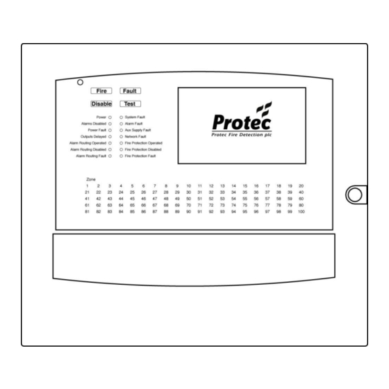
Page 11: Indications And Controls
100 zones (40 zones on a standalone panel) then it is also indicated by the zone indicator flashing red. If the user touches Accept then the zone indicator will remain on but stop flashing. RDM0001/3_2 Page 11 of 70 © 2015 - 2017 Protec Fire Detection plc... -
Page 12: Fire Indications
Zone Indicator Flashing Red The panel has detected a fire in the zone shown. The General Fire indicator will always accompany this and the internal buzzer will be fast pulsing. RDM0001/3_2 Page 12 of 70 © 2015 - 2017 Protec Fire Detection plc... -
Page 13: Fault Indications
The General Fault indicator will be illuminated accompanied by the ‘Aux Supply Fault’ indicator. RDM0001/3_2 Page 13 of 70 © 2015 - 2017 Protec Fire Detection plc... -
Page 14: Network Fault
A fault has been detected on the monitored path to fire protection equipment. This may be a wiring fault or a fire protection interface fault. The connection to the fire protection equipment is no longer reliable. Expert advice should be sought immediately. RDM0001/3_2 Page 14 of 70 © 2015 - 2017 Protec Fire Detection plc... -
Page 15: Disablement Indications
Fire Protection Disabled Activation and faults on the fire protection equipment output are inhibited. The fire protection equipment output will not activate in the event of a fire. RDM0001/3_2 Page 15 of 70 © 2015 - 2017 Protec Fire Detection plc... -
Page 16: Other Indications
The alarms, fire link or fire protection equipment output may not activate immediately in the event of a fire. RDM0001/3_2 Page 16 of 70 © 2015 - 2017 Protec Fire Detection plc... -
Page 17: System Delays
Silence button is touched before a delay has expired. In general, delays only apply to automatic detector activations whilst a manual activation on a zone (Activating a Manual Call Point) overrides delays. RDM0001/3_2 Page 17 of 70 © 2015 - 2017 Protec Fire Detection plc... -
Page 18: Coincidence/Dependency Operation
‘coincidence’ modes where a confirmation signal is required. The confirmation signal is normally the same or a second device generating a fire signal. Mode ‘C’ is the standard coincidence mode used in Protec fire alarm systems. Coincidence operation is used to minimise the effects of false alarms by providing time to investigate the first fire signal and if found to be an unwanted activation, prevent a full evacuation of the premises and an unnecessary call to the fire brigade. -
Page 19: Response To An Alarm
When logged in, touch and hold reset. The panel will reset any latched devices on its loops. The Reset sequence takes about 20 seconds during which time the panel will not detect new fires. RDM0001/3_2 Page 19 of 70 © 2015 - 2017 Protec Fire Detection plc... -
Page 20: New Zone In Alarm
Output group types will be activated as programmed but the Control and Fire Link outputs WILL NOT be activated. If the sound alarms input is set to operate a fire link output this will create a design error. RDM0001/3_2 Page 20 of 70 © 2015 - 2017 Protec Fire Detection plc... -
Page 21: Status Display & Menu Navigation
In this state the panel will have its power on indicator illuminated and the LCD will show the System Normal display, as shown below:- Touch the centre of the screen to display the code entry screen, refer to section 12.8. RDM0001/3_2 Page 21 of 70 © 2015 - 2017 Protec Fire Detection plc... -
Page 22: Navigating The Menus
To leave any menu, touch the EXIT button. As a security measure the panel will exit the menus automatically if no key activity has been detected for 30 minutes. RDM0001/3_2 Page 22 of 70 © 2015 - 2017 Protec Fire Detection plc... -
Page 23: Printing
Touch Enter to accept the entered number 12.4 Printing If the panel has a printer fitted then some menus will offer the option to print. Touch the button to print the information RDM0001/3_2 Page 23 of 70 © 2015 - 2017 Protec Fire Detection plc... -
Page 24: Panel Selection
Each panel comprises a number of cards. Once the user has selected a panel then the list of relevant cards is presented. If searching for a loop device, touch to select the correct loop card. RDM0001/3_2 Page 24 of 70 © 2015 - 2017 Protec Fire Detection plc... -
Page 25: Loop Selection
Each loop comprises up to 200 devices. Search the list for the correct device then touch to select it. Note :- Only addresses with a device assigned will be displayed. RDM0001/3_2 Page 25 of 70 © 2015 - 2017 Protec Fire Detection plc... -
Page 26: Login
User main menu screen – see section 13, or the Level 3a main menu screen – see section 14 Touching the Service Info button will display contact details of the company responsible for servicing your system. RDM0001/3_2 Page 26 of 70 © 2015 - 2017 Protec Fire Detection plc... -
Page 27: The Fault, Disablement And Test Display
The summaries of Disablements, Tests and Other information are displayed in a similar manner to the fault summary below. The ‘Accept’ button at this level is optional and will only be displayed if configured to do so during the panel commissioning. RDM0001/3_2 Page 27 of 70 © 2015 - 2017 Protec Fire Detection plc... - Page 28 ‘Clear System Fault’, refer to section 13.24 Touch Reset to clear latching faults such as loop faults. Any faults that have not been fixed will reappear. RDM0001/3_2 Page 28 of 70 © 2015 - 2017 Protec Fire Detection plc...
-
Page 29: The Fire Alarm Display
To silence the sounders (section 11.4) and to reset the system (section 11.5) requires the user to login (section 12.8) by pressing the ‘To silence touch here and login’ button instead of the usual ‘Login’ button. RDM0001/3_2 Page 29 of 70 © 2015 - 2017 Protec Fire Detection plc... - Page 30 Touching one of the fire events will show details of the fire event:- The screen automatically returns to the standard fire display if no buttons are touched for 30 seconds. RDM0001/3_2 Page 30 of 70 © 2015 - 2017 Protec Fire Detection plc...
-
Page 31: User Menus
Disable / Enable – refer to section 13.9 Settings – refer to section 13.21 Test Menu – refer to section 13.26 History Menu – refer to section 13.31 RDM0001/3_2 Page 31 of 70 © 2015 - 2017 Protec Fire Detection plc... -
Page 32: System View
13.2 System View Touching System View displays options to show the system configuration. RDM0001/3_2 Page 32 of 70 © 2015 - 2017 Protec Fire Detection plc... -
Page 33: Device Detail
16 way board loses the ability to detect a fire event from all its 16 addresses. Touch Locate device to instruct the device to flash its address using its LED RDM0001/3_2 Page 33 of 70 © 2015 - 2017 Protec Fire Detection plc... - Page 34 A device will time out of RVAV mode after 20 minutes however the menu will time out after 30 minutes (Refer to Appendix A for details of the LED flashing) RDM0001/3_2 Page 34 of 70 © 2015 - 2017 Protec Fire Detection plc...
-
Page 35: Algo-Tec Data
13.4 Algo-Tec Data Algo-Tec Data is only available for detector devices. Touching Algo-Tec Data displays the algorithm data for the device. RDM0001/3_2 Page 35 of 70 © 2015 - 2017 Protec Fire Detection plc... -
Page 36: Panel Summary
13.5 Panel Summary Touching Panel Summary displays the list of panels on the system. Select a Panel (section 12.4) to display its loop device summary. RDM0001/3_2 Page 36 of 70 © 2015 - 2017 Protec Fire Detection plc... -
Page 37: Device State
Touch a device icon to display the device details. Refer to section 13.3 for the device details screen Press Help for information about the screen Note that indication of Device Pre-Alarm is not currently supported. RDM0001/3_2 Page 37 of 70 © 2015 - 2017 Protec Fire Detection plc... -
Page 38: Input Groups
Note: - The Input Groups – Active menu may be blank if no input groups are active. Press View All to view all input groups (Active and Inactive). Press View Active to return to viewing only the active input groups. RDM0001/3_2 Page 38 of 70 © 2015 - 2017 Protec Fire Detection plc... -
Page 39: Output Groups
Note: - The Output Groups – Active menu may be blank if no output groups are active. Press View All to view all output groups (Active and Inactive). Press View Active to return to viewing only the active output groups. RDM0001/3_2 Page 39 of 70 © 2015 - 2017 Protec Fire Detection plc... -
Page 40: Disable / Enable
Disabling outputs temporarily prevents them from signalling that the system is in a fire state. A disablement remains in place until the user cancels (normalises) 13.10 Current Disablements Touching Current Disablements displays the disablement summary. RDM0001/3_2 Page 40 of 70 © 2015 - 2017 Protec Fire Detection plc... -
Page 41: Zone Disablements
The list of zones contains 10000 zones, many of which may not be used. The system will allow these unused zones to be disabled however no devices will actually be disabled. Note: - A single panel will only display 40 zones not 10000. RDM0001/3_2 Page 41 of 70 © 2015 - 2017 Protec Fire Detection plc... - Page 42 This indicates that all the devices in this zone are disabled. This disablement can only be removed in the all devices zone disablement menu. RDM0001/3_2 Page 42 of 70 © 2015 - 2017 Protec Fire Detection plc...
-
Page 43: Device Disablement
Touch a device address to disable its input, touch it again to normalise it (cancel the disablement). Disabling a device without an input e.g. a sounder, is possible but does not prevent the sounder from activating. RDM0001/3_2 Page 43 of 70 © 2015 - 2017 Protec Fire Detection plc... -
Page 44: Output Group Disablement
Output groups of type ‘Alarm’ are greyed out because they cannot be disabled. Output groups that are greyed out may be disabled using the panel logic and are usually operated by a keyswitch or invisible switch device. RDM0001/3_2 Page 44 of 70 © 2015 - 2017 Protec Fire Detection plc... -
Page 45: Output Disablement
Touch a disablement option to disable it, touch it again to normalise it (cancel the disablement). Outputs that are greyed out and listed as “unavailable” are disabled via the panel logic and are usually operated by a keyswitch or invisible switch device. RDM0001/3_2 Page 45 of 70 © 2015 - 2017 Protec Fire Detection plc... -
Page 46: Disable All Fire Links
‘Non-fire’ outputs are typically interface devices that do not control equipment when there is a fire event. These outputs are not affected when the system is silenced or reset. RDM0001/3_2 Page 46 of 70 © 2015 - 2017 Protec Fire Detection plc... -
Page 47: Settings
13.21 Settings Touching Settings displays the settings menu. RDM0001/3_2 Page 47 of 70 © 2015 - 2017 Protec Fire Detection plc... -
Page 48: Set Time / Date
When finished setting both the Time and Date, touch set to save the information. To exit without changing the Time or Date, touch Cancel. RDM0001/3_2 Page 48 of 70 © 2015 - 2017 Protec Fire Detection plc... -
Page 49: Show Configuration
13.24 Clear System Fault Touch the Clear System Fault button to remove any system faults. If the cause of the system fault remains then the system fault will reappear. RDM0001/3_2 Page 49 of 70 © 2015 - 2017 Protec Fire Detection plc... -
Page 50: Software Versions
Press Software Versions to display the list of panels on the system. Select a Panel (section 12.4). The panel cards and firmware versions will be displayed. 13.26 Test Menu Touch Test Menu to display the test options. RDM0001/3_2 Page 50 of 70 © 2015 - 2017 Protec Fire Detection plc... -
Page 51: Lamp / Buzzer Test
13.27 Lamp / Buzzer Test Touch to test the LCD, panel buzzer and the LED indications. RDM0001/3_2 Page 51 of 70 © 2015 - 2017 Protec Fire Detection plc... -
Page 52: Zone Test
If a device is activated in a zone under test then only the alarm outputs, including talking sounders, on that panel will be activated (assuming the alarm outputs have been enabled during test – see section 13.29). RDM0001/3_2 Page 52 of 70 © 2015 - 2017 Protec Fire Detection plc... -
Page 53: Test Options
Auto Reset / Auto Reset Delay If ‘Auto Reset’ is ‘Enabled’ then a test fire event will be automatically reset after a pre-programmed delay. This delay is the ‘Auto Reset Delay’ time. RDM0001/3_2 Page 53 of 70 © 2015 - 2017 Protec Fire Detection plc... -
Page 54: Complete System Test
Note: - When a device is activated in complete test mode, the alarm outputs, including talking sounders, will be activated on all panels (assuming the alarm outputs have been enabled during test – see section 13.29). RDM0001/3_2 Page 54 of 70 © 2015 - 2017 Protec Fire Detection plc... -
Page 55: History
13.31 History Touch History to display the Historic log options. 13.32 View all fires Touch View all fires to view all the fire events from the log. RDM0001/3_2 Page 55 of 70 © 2015 - 2017 Protec Fire Detection plc... -
Page 56: View All Non-Fires
13.33 View all non-fires Touch View all non-fires to view all events from the log except fire events. RDM0001/3_2 Page 56 of 70 © 2015 - 2017 Protec Fire Detection plc... -
Page 57: View By Type
Touch Date to display events since a specific date and time. In the above example, the user has chosen to display events since 8:30 on the 10 September 2017. RDM0001/3_2 Page 57 of 70 © 2015 - 2017 Protec Fire Detection plc... -
Page 58: Historic Alarm Count
The alarm count is a count of the number of times that the panel has entered the fire alarm state since the count was last reset. Note: - The user cannot reset the alarm count. RDM0001/3_2 Page 58 of 70 © 2015 - 2017 Protec Fire Detection plc... -
Page 59: Printer Menu
Note; - The printer menu option is only available on panels configured to have a printer. Touch to print all current fault events. Touch to print all current disablement events. Touch to print all current test mode events. RDM0001/3_2 Page 59 of 70 © 2015 - 2017 Protec Fire Detection plc... - Page 60 A competent person trained to undertake such work MUST carry out any internal maintenance work. Touch to print the last one hundred events that the panel has logged. RDM0001/3_2 Page 60 of 70 © 2015 - 2017 Protec Fire Detection plc...
-
Page 61: Exchanging Loop Devices
Settings – refer to section 13.21 Test Menu – refer to section 13.26 History Menu – refer to section 13.31 Tools Menu – refer to section 14.2 RDM0001/3_2 Page 61 of 70 © 2015 - 2017 Protec Fire Detection plc... -
Page 62: Tools Menu
Printer Menu – see section 13.36 (only appears if a printer is fitted) 14.3 Loop Tools Pressing the loop tools button will show the option for exchanging loop devices. RDM0001/3_2 Page 62 of 70 © 2015 - 2017 Protec Fire Detection plc... -
Page 63: Exchange Device Menu
A maximum of 8 devices per loop can be exchanged at any one time. Press cancel to exit the exchange menu. Press OK to begin the exchange of devices. RDM0001/3_2 Page 63 of 70 © 2015 - 2017 Protec Fire Detection plc... - Page 64 A warning is given asking if the user wishes to continue, incorrect exchanging of devices could result in a configuration error or the incorrect operation of devices. Press cancel to abandon the exchange or to select a different loop. RDM0001/3_2 Page 64 of 70 © 2015 - 2017 Protec Fire Detection plc...
- Page 65 Select the replacement device you wish to exchange with. Note that devices of a different type to the original are greyed out and cannot be exchanged. RDM0001/3_2 Page 65 of 70 © 2015 - 2017 Protec Fire Detection plc...
- Page 66 Press cancel to select a different replacement device to exchange with. Press OK to confirm the selection of the replacement device. After pressing OK the user is asked if they wish to save the changes. RDM0001/3_2 Page 66 of 70 © 2015 - 2017 Protec Fire Detection plc...
- Page 67 Press exit to cancel the exchange and leave the menu (Any changes will not be saved). Press save after all exchanges are finished to save the changes. A progress bar will be displayed whilst the changes are saved. RDM0001/3_2 Page 67 of 70 © 2015 - 2017 Protec Fire Detection plc...
-
Page 68: Appendix A, Rvav Description
See Note below Address 102 • 1 + 1 = 102 Fire LED State 1.5 seconds 1 second Note: The delay following a zero is reduced to one second RDM0001/3_2 Page 68 of 70 © 2015 - 2017 Protec Fire Detection plc... -
Page 69: Standards, Directives And Regulations Information
16.0 Standards, directives and regulations information 0832-CPR-F0179 201ag Protec Fire Detection plc, Nelson, Lancashire, England BB9 6RT PFD-CPR-0114 This equipment has been manufactured in conformance with the requirements of all applicable EU council directives and regulations. BS EN 54-2:1997 + A1:2006... - Page 70 The policy of Protec Fire Detection plc is one of continuous improvement. As such we reserve the right to make changes to product specifications at any time and without prior notice. Errors and omissions excepted. Electrical or electronic devices that are no longer serviceable must be collected separately and sent for environmentally compatible recycling (in accordance with the European Waste Electrical and Electronic Equipment Directive).
Need help?
Do you have a question about the Algo-Tec 6500 and is the answer not in the manual?
Questions and answers