CapstanAG PinPoint II Operator's Manual
Spray application
Hide thumbs
Also See for PinPoint II:
- Operator and maintenance manual (78 pages) ,
- Quick reference information (2 pages)

Related Manuals for CapstanAG PinPoint II


Summary of Contents for CapstanAG PinPoint II
- Page 1 PinPoint™ II Spray Application Configurations: Synchro™ Mode SharpShooter™ Mode Operator Manual 122200-210 Rev. D | Revised 02/2020 | ©2020 Capstan Ag Systems, Inc.
- Page 2 Thank you for your business! At CapstanAG, our goal is to redefine the way people do their chemical application. Our PWM control systems have been setting the bar for maximum productivity for more than 20 years. Our focus on performance, support, and education have dramatically changed the landscape of agricultural chemical application.
-
Page 3: Table Of Contents
Contents Contents Chapter 1: Introduction.................7 This Manual..........................7 System Identification........................7 Chapter 2: Safety...................9 Signal Words..........................9 Emergency Safety........................9 Personal Protective Equipment....................10 Safety Signs..........................10 Pressurized Fluid Lines......................10 Chemical Safety........................10 Battery Safety..........................10 Chapter 3: Warranty................11 Limited Warranty........................11 Chapter 4: System Installation............13 Prepare for Installation and Setup....................13 Tip Selection and Capacities.................... - Page 4 Operate in Automatic Pressure Control (AUTO) Mode............75 Manual Mode Operation......................76 ™ Spray Without the PinPoint II System................... 77 Spray Through the CapstanAG Nozzle Valves............. 77 Spray Through Alternate Valve Bodies................. 77 Nozzle Display.......................... 78 Overlap Control......................... 79 Mapping.............................79 Upload a Boundary File to the CapView...............
- Page 5 Contents ™ Convert a Batch of Shapefiles to PinPoint II Maps............ 87 ™ Uninstall the CapMaps Software................87 Overlap Distance........................89 Change the Overlap Distance..................89 Flowmeter Signal........................90 ™ Change the Flowmeter Settings—Synchro Mode............90 ™ Change the Flowmeter Settings—SharpShooter Mode ..........90 Turn Compensation........................91 Counters............................
- Page 6 ™ General System Layout—Synchro Mode................135 ™ General System Layout—SharpShooter Mode..............137 Index........................139...
-
Page 7: Chapter 1: Introduction
If you are not the original owner of this machine, it is in your interest to contact your local CapstanAG dealer to inform them of this unit's serial number. Providing this information will help CapstanAG notify you of any issues or product improvements. - Page 8 Introduction © ™ 2020 Capstan Ag Systems, Inc. PinPoint...
-
Page 9: Chapter 2: Safety
Safety Chapter 2: Safety Signal Words DANGER: Indicates an imminent hazard which, if not avoided, will result in death or serious injury. This signal word is limited to the most extreme situations, typically for machine components that, for functional purposes, cannot be guarded. Warning: Indicates a potential hazard which, if not avoided, could result in death or serious injury, and includes hazards that are exposed when guards are removed. -
Page 10: Personal Protective Equipment
These labels and safety messages warn all personnel about hazardous chemicals or potentially unsafe chemical conditions that may exist while working around agricultural application equipment. CapstanAG add-on application systems for OEM and retrofit agricultural application equipment (booms and tool bars) may contain HCS pictographs and GHS safety labels and safety signal word messages. -
Page 11: Chapter 3: Warranty
The terms of this warranty do not in any way extend to any product which was not manufactured by us or one of our affiliates. While necessary maintenance or repairs on your CapstanAG product can be performed by any company, we recommend that you use only authorized CapstanAG dealers. Improper or incorrectly performed maintenance or repair voids this warranty. - Page 12 Warranty What is the period of coverage? We warrant to you that our products are free from defects in material and workmanship in normal use and service for a period of one year from date of purchase. How do you get service? Our obligation under this warranty shall be limited to the repairing or replacing at our option, the component which our inspection discloses to be defective, free of charge, return freight paid by us, provided you: (i) Notify us of defect within thirty (30) days of failure;...
-
Page 13: Chapter 4: System Installation
System Installation Chapter 4: System Installation Prepare for Installation and Setup CAUTION: Before installation, operation, or service to the system, read and understand the machine’s operator manual and the system operator manual. Chemical residue may be present on/in the OEM equipment. Use the correct personal protective equipment. Important: Before installation, make sure that all parts are included in the shipping boxes using the list of parts included in the order. -
Page 14: Valve Assembly Types And Component Identification
System Installation Valve Assembly Types and Component Identification Important: Make sure that you have the correct valves and components for your system. 7-Watt Coil Components Fig. 3: Item Description Arag High Flow Arag Part Tee Jet Part Wilger Part Part Number Number Number Number... -
Page 15: 12-Watt Coil Components
System Installation 12-Watt Coil Components Fig. 4: Item Description Arag High Arag Part Tee Jet Part Wilger Part Flow Part Number Number Number Number Coil 625147-011 625147-011 625147-011 625147-011 Plunger—2-Slot Standard 716009-111 716009-111 716009-111 716009-111 Plunger—4-Slot Standard 716009-114 716009-114 716009-114 716009-114 Plunger—4-Slot 716009-113... -
Page 16: 7-Watt-15 Series Coil Assembly Components
System Installation 7-Watt—15 Series Coil Assembly Components Fig. 5: Item Description Arag High Flow Arag Part Tee Jet Part Wilger Part Part Number Number Number Number 7-Watt Coil Assembly 116189-111 116189-111 116189-111 116189-111 Plunger Assembly 716009-114 716009-114 716009-114 716009-114 Inner-valve O-ring 715022-204 715022-204 715022-204... -
Page 17: 12-Watt-24 Series Coil Assembly Components
System Installation 12-Watt—24 Series Coil Assembly Components Fig. 6: Item Description Arag High Flow Arag Part Tee Jet Part Wilger Part Part Number Number Number Number 12-Watt Coil 625147-011 625147-011 625147-011 625147-011 Assembly Plunger Assembly— 716009-114 716009-114 716009-114 716009-114 Standard Spring Plunger Assembly—... -
Page 18: Assemble The Nozzle Valves
System Installation Assemble the Nozzle Valves 1. Remove the drip check valve and diaphragm cap from each nozzle body. Fig. 7: 2. Install the O-ring (1) onto the nozzle valve assembly (2). 3. Install the nozzle valve assembly onto the nozzle body (3). 4. -
Page 19: Move The Spray Tube Mount (Nozzle Valve Interference)
System Installation Move the Spray Tube Mount (Nozzle Valve Interference) Fig. 8: If a spray tube mount (1) prevents nozzle valve installation: 1. Loosen the spray tube mount bolts (2). 2. Slide the spray tube mount away from the nozzle valve assembly (3) until the nozzle valve assembly can be properly installed. -
Page 20: Gateway Hub Identification
System Installation Gateway Hub Identification Fig. 9: Boom 1—Connector for boom 1 extension harness Boom 2—Connector for boom 2 extension harness Boom 3—Connector for boom 3 extension harness Boom 4—Connector for boom 4 extension harness Boom 5—Connector for boom 5 extension harness Boom 6—Connector for boom 6 extension harness Boom 7—Connector for boom 7 extension harness Boom 8—Connector for boom 8 extension harness... -
Page 21: Install The Psi Nav Commander Module
System Installation Install the PSI NAV Commander Module Note: For detailed information on the installation of the PSI NAV Commander module, see the installation instruction sheet that may be supplied. Fig. 10: 1. Mount the PSI NAV Commander Module. The module must be oriented correctly when mounting, with the LEDs (1) and the note (2) at the top of the module. - Page 22 System Installation 3. Connect the harness plugs at the VCMs and the nozzle valves. Fig. 11: Additional VCMs and Y-adapters are required on boom sections that have more than nine nozzles. 4. Mount additional VCMs (1) and Y-adapters (2) at a central location in the boom section. 5.
-
Page 23: Install The Vcm Extension Harnesses
System Installation Install the VCM Extension Harnesses 1. Connect each extension harness to the VCM. 2. Route the extension harnesses along the boom to the Gateway hub. Make sure that there is enough slack in the extension harnesses to raise and lower the booms and to avoid pinch points at the boom fold and pivot points. -
Page 24: Install The Pressure Sensor Adapter Harness
System Installation Fig. 13: 1. Remove the existing machine pressure sensor (1) from the boom manifold. 2. Install the tee fitting (2) and other hardware with sealant tape. 3. Install the new pressure sensor (3) with sealant tape. Important: Do not over-tighten the pressure sensor when installing into plastic tee fittings. 4. -
Page 25: Install The Flowmeter Harness
System Installation Install the Flowmeter Harness 1. Record flowmeter tag g/min information. The information will be used during the CapView setup. Fig. 14: 2. Disconnect the machine flowmeter harness (1). 3. Install the flowmeter harness (2) between the flowmeter and the existing harness. 4. -
Page 26: Install The Boom Shutoff Adapter
System Installation Install the Boom Shutoff Adapter Fig. 15: 1. Connect a connector (1) for the boom shutoff adapter to the BOOM 1-6 port (2) and BOOM 7-12 port (3) on the Gateway hub. Boom shutoff adapter PN—118606-051 2. Connect the 12-pin connector (4) into the shutoff harness. The shutoff harness is different depending on your machine. -
Page 27: Install The Capview
System Installation Install the CapView Fig. 16: 1. Install the RAM mount (1) and hardware inside the machine cab. Note: Make sure that the CapView can be seen and reached from the operator seat. 2. Remove the four screws from the back of the CapView (2). 3. -
Page 28: Install The Battery Harness
System Installation Install the Battery Harness 1. Route the battery harness connectors to the Gateway hub. 2. Connect the positive (+) red cable to the red power terminal on the Gateway hub. 3. Connect the negative (-) black cable to the black terminal on the Gateway hub. 4. -
Page 29: Install The Power Disconnect Breaker Kit (Optional)
System Installation Install the Power Disconnect Breaker Kit (Optional) A power disconnect breaker kit is available for applications when unhooking the battery power cable is not desired. Fig. 18: 1. Disconnect the battery cables. 2. Cut and strip the cables at the desired disconnect location. 3. - Page 30 System Installation © ™ 2020 Capstan Ag Systems, Inc. PinPoint...
-
Page 31: Chapter 5: System Setup
System Setup Chapter 5: System Setup CapView Button Descriptions Icon Name Description POWER Press the button to start or shut down the CapView display and the rate controller The LED light illuminates to show what is active AUTO/ Press the button to change between Manual or Automatic operation mode MANUAL TURN Press the button to engage or disengage turn compensation... -
Page 32: Start The Capview
System Setup Start the CapView Before starting the machine engine, always make sure that the CapView display and rate controller are off. Fig. 19: 1. Start the machine engine. 2. Press the POWER button (1) to start the CapView and the rate controller. 3. -
Page 33: System Setup
System Setup System Setup The system is set up at the factory. These steps are only required when modifications have been ™ made during installation or if changes were made to the machine after the PinPoint II order was placed. 1. -
Page 34: Do The Factory Reset Procedure
System Setup Do the Factory Reset Procedure Fig. 20: 1. Make sure that the key switch power is on. 2. Press the POWER button (1) on the CapView. 3. Press the SYSTEM SETUP button (2) on the CapView. 4. Use the up or down arrows (3) to select Operation Mode (4). 5. - Page 35 System Setup Fig. 21: 12.Use the LEFT or RIGHT arrows (1) to select YES (2). 13.Press the ENTER button (3). The CapView will turn off. Leave the key switch on to keep power to the hub. 14.Press the POWER button (4). A warning screen will show after a factory reset or when no data is present in the VCMs.
-
Page 36: Restore System Configuration Or Select Settings
System Setup Restore System Configuration or Select Settings Contact your local CapstanAG representative for initial system configuration or select settings files if this is the initial setup for your system. Fig. 22: 1. Insert the USB thumb drive (1) into the back of the CapView (2). -
Page 37: Change The Units Of Measure
System Setup Change the Units of Measure Fig. 23: 1. Press the SYSTEM SETUP button (1). 2. Use the UP or DOWN arrow buttons (2) to select Units (3) from the System Setup menu. 3. Press the ENTER button (4). 4. -
Page 38: Do The Location Setup Procedure
System Setup Do the Location Setup Procedure Fig. 24: 1. Press and hold the LOCATION SETUP button (1) for 10 seconds. Note: It is normal for the screen to change as you press and hold the button. 2. Use the LEFT or RIGHT arrow buttons (2) to select AUTO SETUP (3). 3. -
Page 39: Do The Nozzle Spacing Setup Procedure
System Setup Do the Nozzle Spacing Setup Procedure 1. Use the UP or DOWN arrow buttons to set the desired nozzle spacing. The default setting is 20 in. 2. Press the ENTER button. Fig. 25: This screen shows a picture of the sprayer with the VCMs located on the boom. The VCMs are arranged on the boom from left to right according to the VCM serial number order and oriented according to the position of the potted tube relative to the center mast (1). - Page 40 System Setup 8. Repeat the process from left to right, until all of the VCMs are in to the proper location and orientation. 9. When finished, press the ESCAPE button. 10.Make sure that the master switch is engaged and the boom section switches are off. 11.Engage and disengage each boom section control switch to correlate the boom valves to the VCMs.
- Page 41 System Setup Numbers 1 to 9 represent the physical location of the nine nozzles on the highlighted VCM. Number 1 is the nozzle closest to the VCM (potted tube), and number 9 is the farthest from the VCM (potted tube). The center columns, under Nozzle Location, show the location data of the highlighted VCM on the sprayer boom.
-
Page 42: System Setup Menus
System Setup System Setup Menus System Setup Menu Descriptions Line Title Line Action Number Description Operation Mode Press ENTER to change ™ ™ ™ The PinPoint II system can operate in three modes: SharpShooter , Synchro , or N- ™ ™... - Page 43 If the PinPoint II system is not using nozzles that use the CapstanAG nozzle diagnostics properly, the nozzle diagnostics can be disabled here. CapstanAG uses this feature on demonstration units and development units where lights are substituted for valves or reset to coil only.
- Page 44 Overlap Distance Press ENTER to change CapstanAG has coined the term “Cat Whiskers” to describe this feature. Each nozzle has five imaginary cat whiskers by which it checks and marks the overlap map. There is a whisker in front, behind, right, left, and center. The center whisker marks the map as being sprayed.
-
Page 45: Advanced Settings-Synchro ™ Mode Operation
System Setup ™ Advanced Settings—Synchro Mode Operation Line Title Line Action Number Description Hour Meter The hour meter shows the accumulated hours. The hour meter starts when at least one nozzle is on. Compass Heading Press ENTER to and then YES to calibrate. The 3-dimensional compass is generally not used. - Page 46 System Setup Line Title Line Action Number Description Gain - Differential Press ENTER to change. The differential gain causes the control system to accumulate errors faster when errors are small. The higher the number, the more sensitive the control system. To stabilize an oscillating system, use a lower number.
- Page 47 System Setup Line Title Line Action Number Description Forward/Reverse Detection Press ENTER to change. For individual nozzle control to correctly perform, the system must know if the sprayer is moving in forward or reverse. When the forward/reverse detection is set to OFF=Fwd Rev Switch, the system is looking for a 12V (reverse beeper) input to tell it the sprayer is reversing.
- Page 48 System Setup Line Title Line Action Number Description Servo Type Press ENTER to change. Case Sprayers 2017 and before will use PWM 12 Volt. Case sprayers 2017 and after will use PWM Ground. The RoGator factory controller uses PWM Ground. The Apache factory controller uses PWM Ground or Bypass Servo depending upon plumbing.
- Page 49 Nozzle Pulse Frequency Press ENTER to change. All CapstanAG sprayer systems run at 10 pulses per second pulse frequency. To run a faster pulse frequency, enter a larger number. CapstanAG does not recommend pulse frequencies slower than 10Hz in sprayer applications.
- Page 50 If major components are changed, a factory reset may need to be performed. Contact Information Selecting this line will open up a page with the CapstanAG toll-free phone number, website, and a QRC code that will direct you to the website. ©...
-
Page 51: Advanced Settings-Sharpshooter ™ Mode Operation
System Setup ™ Advanced Settings—SharpShooter Mode Operation Line Title Line Action Number Description Hour Meter The hour meter shows the accumulated hours. The hour meter starts when at least one nozzle is on. Compass Heading Press ENTER to and then YES to calibrate. The 3-dimensional compass is generally not used. - Page 52 System Setup Line Title Line Action Number Description Gain - Differential Press ENTER to change. The differential gain causes the control system to accumulate errors faster when errors are small. The higher the number, the more sensitive the control system. To stabilize an oscillating system, use a lower number.
- Page 53 System Setup Line Title Line Action Number Description Forward/Reverse Detection Press ENTER to change. For individual nozzle control to correctly perform, the system must know if the sprayer is moving in forward or reverse. When the forward/reverse detection is set to OFF=Fwd Rev Switch, the system is looking for a 12V (reverse beeper) input to tell it the sprayer is reversing.
- Page 54 Nozzle Pulse Frequency Press ENTER to change. All CapstanAG sprayer systems run at 10 pulses per second pulse frequency. To run a faster pulse frequency, enter a larger number. CapstanAG does not recommend pulse frequencies slower than 10Hz in sprayer applications.
- Page 55 With a properly prepared “cheat sheet,” a factory reset only takes a few minutes. Contact Information Selecting this line will open up a page with the CapstanAG toll-free phone number, website, and a QRC code that will direct you to the website. ©...
-
Page 56: Do The Nozzle Setup Procedure
System Setup Do the Nozzle Setup Procedure 1. Press the NOZZLE SETUP button. Nozzle Setup is to set up each individual nozzle for: • Rank • Flow Value—Used to adjust nozzle flow for fence row and wheel track • Nozzle Size—Used to adjust to match tip size •... -
Page 57: Set The Preset Buttons
System Setup Set the Preset Buttons Fig. 28: 1. Press the NOZZLE SETUP button (1). 2. Use the UP or DOWN arrow buttons (2) to go to the Nozzle Size. 3. Press the ENTER button (3). 4. Use the UP or DOWN arrow buttons to change the value to match the desired tip size. 5. -
Page 58: System Dry Tests
System Setup System Dry Tests Do these procedures to make sure that the soft boom and nozzle valves are operating correctly. Do the Boom Shutoff Dry Test 1. Make sure that the engine is off and the key is on. 2. -
Page 59: Do The Key Fob Boom Shutoff Dry Test
System Setup Do the Key Fob Boom Shutoff Dry Test Using the key fob to operate the boom sections lets the operator see the operation of the nozzle valves. Use the key fob to operate each nozzle. Fig. 29: 1. Activate the Nozzle Control (Key Fob) on the CapView. a) Press the SYSTEM SETUP button (1). - Page 60 System Setup Note: If a nozzle valve is leaking or dripping, use a marker to mark the nozzle valve. Continue to check all nozzle valves. 5. Press the center button on the Key FOB to turn OFF the whole boom. 6.
-
Page 61: System Wet Tests
System Setup System Wet Tests Do these procedures to make sure that the soft boom and nozzle valves are operating correctly. Do the Boom Shutoff Wet Test 1. Fill the sprayer with approximately 400 gallons of water. 2. Make sure that the CapView and rate controller are off. 3. -
Page 62: Do The Key Fob Boom Shutoff Wet Test
System Setup Do the Key Fob Boom Shutoff Wet Test Fig. 31: Use the key fob to operate the boom sections while not in the cab near the CapView display. The key fob lets the operator see the operation of the nozzle valves. The Key Fob works to check for plugged tips without wasting a significant amount of product. -
Page 63: Do The Pressure Control Test
System Setup Do the Pressure Control Test 1. Make sure that the tank has enough water to do the procedure. 2. Make sure that the CapView and the rate controller are off. 3. Start the machine engine and set the engine to idle speed. 4. -
Page 64: Do The Compass Calibration Procedure
System Setup Fig. 32: 1. Put a person at point A and another at point B. The people should be on either side of the machine at the starting point. 2. Start spraying and move the machine forward. 3. Continue to move straight forward for approximately 150 ft (45 m). 4. - Page 65 System Setup Fig. 33: 2. Press the SYSTEM SETUP (1) button. 3. Use the up or down arrows (2) to select ADVANCED SETTINGS. 4. Press the ENTER button (3). 5. Use the up or down arrows to select Compass Heading (4). 6.
-
Page 66: Setting The Gps Settings
System Setup Setting the GPS Settings Fig. 34: Before operation, make sure that the GPS setting values are correct. Measure and record the values for: Antenna Ahead of the Rear Axle—Inches from the rear axle centerline to the GPS antenna centerline •... - Page 67 System Setup Fig. 35: 1. Press the SYSTEM SETUP button (1). 2. Use the UP or DOWN arrow buttons (2) to select GPS-Ant. Ahead of Rear Axle (3). 3. Enter the number of inches from the rear axle centerline to the GPS antenna centerline. This value is used for GPS overlap control to shut off nozzles in the proper place.
-
Page 68: Machine Specific Information
System Setup Machine Specific Information Location Setup Information Machine Type VCM Orientation Left Right Boom Section #1 Left VCM SN: Nozzle Qty. Right VCM SN: Nozzle Qty. Move these nozzles to Boom #2: Boom Section #2 Left VCM SN: Nozzle Qty. Right VCM SN: Nozzle Qty. - Page 69 System Setup Machine Type VCM Orientation Left Right Boom Section #8 Left VCM SN: Nozzle Qty. Right VCM SN: Nozzle Qty. Move these nozzles to Boom #7: Move these nozzles to Boom #9: Boom Section #9 Left VCM SN: Nozzle Qty. Right VCM SN: Nozzle Qty.
-
Page 70: System Setup Information
System Setup System Setup Information Line Number Line Name Actual Setting Operation Mode Controller Gallon Counter Actual Gallon Counter Controller Acre Counter Actual Acre Counter Controller Gallons Per Minute Actual Gallons Per Minute Nozzle Control (Key FOB) Pressure 1 System Voltage Display Backlight LED Brightness Beeper Volume... -
Page 71: Advanced Settings-Synchro ™ Setup Information
System Setup ™ Advanced Settings—Synchro Setup Information Line Number Line Name Actual Setting Hour Meter Compass Heading Compass Offset USB Mode Deadband Pressure Gain - System Gain - Proportional Gain - Integral Gain - Differential Total Number Valve Expected Scrolling Enable/Disable GPS - Antenna Ahead Of Rear Axle GPS - Antenna Right Of Center... - Page 72 System Setup Line Number Line Name Actual Setting Nozzle Pulse Frequency Nozzle PWM Minimum Nozzle PWM Maximum Flowmeter Minimum GPM Flowmeter Output Type Flowmeter Calibration Flowmeter Error Limit Flowmeter Error Minimum Valves On Navigation IMU Pressure Command GPS Lag Time Factory Reset Contact Information ©...
-
Page 73: Advanced Settings-Sharpshooter ™ Setup Information
System Setup ™ Advanced Settings—SharpShooter Setup Information Line Number Line Name Actual Setting Hour Meter Compass Heading Compass Offset USB Mode Deadband Pressure Gain - System Gain - Proportional Gain - Integral Gain - Differential Total Number Valve Expected Scrolling Enable/Disable GPS - Antenna Ahead Of Rear Axle GPS - Antenna Right Of Center... - Page 74 System Setup Line Number Line Name Actual Setting Flowmeter Output Type Flowmeter Calibration Flowmeter Error Limit Flowmeter Error Low Flow Hold Flow Rate Rate Sync Test Speed Minimum Valves On Navigation IMU Pressure Command GPS Lag Time Factory Reset Contact Information ©...
-
Page 75: Chapter 6: Operation
Operation Chapter 6: Operation Operate in Automatic Pressure Control (AUTO) Mode Spraying is usually done in AUTO mode. ™ The PinPoint II system default is manual mode, to change to AUTO mode: 1. Start the machine engine. 2. Press the POWER button to start the CapView and the rate controller. 3. -
Page 76: Manual Mode Operation
Operation Manual Mode Operation Manual mode is usually used for troubleshooting purposes, should the operator encounter rate or pressure instability issues while spraying. Switching to manual mode could allow the operator to finish a field or job before contacting the dealer to solve the problem. Fig. -
Page 77: Spray Without The Pinpoint ™ Ii System
The nozzle valves will open and close with the boom signal (without pulsing). Spray Through Alternate Valve Bodies Note: Use of alternate valve bodies is recommended for high flow applications (30 gal or more per acre) if you do not have CapstanAG high-flow valve assemblies. If using WILGER nozzle bodies: •... -
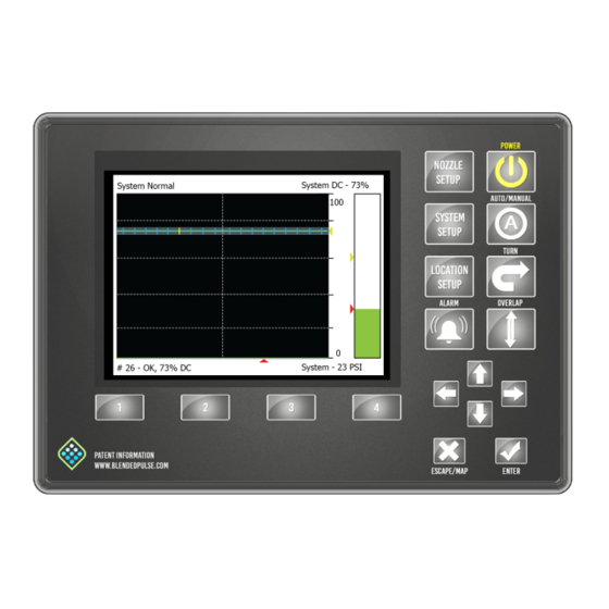
Page 78: Nozzle Display
Operation Nozzle Display Fig. 38: Each nozzle on the boom’s duty cycle is indicated with a blue tick mark (1) on the scale. The bottom of the graphic is 0%, and the top is 100%. The grid lines (2) are in 20% increments. A vertical grid line (3) indicates the center of the boom. -
Page 79: Overlap Control
Operation Overlap Control Press the OVERLAP button to turn the overlap control on or off. Overlap can be turned off for situations that include: • Spraying Rinse Water • Troubleshooting • No GPS Signal • Other Mapping Fig. 39: Make sure that the OVERLAP is off before you enter the MAP menu. Press the ESCAPE/MAP button (1) to go to the Save Map Menu. -
Page 80: Upload A Boundary File To The Capview
Operation Select Save Map As... (3) to give the map a specific name. Select Retrieve Map... (4) to load a map that has already been made. Select Delete Map... (5) to delete the current map. RECOMMENDATION: If you are done spraying the field, select Delete Map..Press the UP or DOWN arrow buttons (6) to select the desired map setting. -
Page 81: Use A Map On The Capview
Operation Use a Map on the CapView Fig. 41: 1. Press the ESCAPE/MAP button (1). 2. Use the up or down arrow button (2) to select Retrieve Map (3). 3. Press the ENTER button (4). 4. Use the up or down arrow button to select the desired boundary map (5). 5. -
Page 82: Download Maps
Operation Download Maps Fig. 42: 1. Insert a USB device into the back of the CapView. Note: Use a USB device no larger than 64 GB in the CapView. The USB Hose Menu will show. 2. Select Download Maps (1). 3. -
Page 83: Capmaps ™ -Boundary Mapping
Fig. 43: 1. On your computer, open a web browser and go to capstanag.com/CapMaps (1). Important: Capital letters must be used for the C and M in CapMaps when typing in the web address. - Page 84 Operation Fig. 44: 9. Click Next > (1). 10.Make sure that the program will be installed in the desired location (2). 11.Click Next > (3). 12.Click Next > (4). You can watch the progress of the software installation (5). 13.When the installation is complete, click Close (6). ™...
-
Page 85: Draw A Map
Operation Draw a Map ™ 1. Open the CapMaps Software shapefile converter application. Fig. 45: 2. Go to: File > New Map (1). 3. Use the + or - to zoom to the desired location. 4. Select the type of map (2) you would like to view while setting polygons in the map selection field: •... - Page 86 12.If points are added within a no spray area, that area (1) will become a spray area. 13.When all of the spray/no spray areas are on the map, select: File > Save As PinPoint II Map. Important: Make sure that you save the map to an external memory device, like a thumb drive.
-
Page 87: Convert A Shapefile Into A Pinpoint ™ Ii Map
• Closed cycle maps 5. To save a shapefile as a PinPoint II boundary files, select File > Save As PinPoint II Map. Important: Make sure that you save the map to an external memory device, like a thumb drive. - Page 88 Operation Fig. 51: 1. Open the Control Panel on your computer. 2. Click on Uninstall a Program (1). 3. Double click CapMapsSetup (2) from the list of installed programs. 4. Click Yes (3) to confirm the uninstall of the program. 5.
-
Page 89: Overlap Distance
Operation Overlap Distance ™ The PinPoint system uses 1-meter-squares to record where spraying has occurred. Any nozzle applying product that touches one of these squares will cause the system to consider this as an area that has been applied. As the machine travels along, each nozzle looks to see if the approaching square has been applied or not. -
Page 90: Flowmeter Signal
Operation Flowmeter Signal ™ Since the rate controller does not know the PinPoint II system is shutting off nozzles, the system manipulates the flowmeter signal to cause the rate controller to apply the proper rate. At low flow rates, the system replaces the turbine flowmeter signal with a calculated value that is accurate down to a single nozzle. -
Page 91: Turn Compensation
Turn compensation can be turned off for situations that include troubleshooting and no GPS. Press the TURN button on the CapView display to turn on and off the turn compensation feature. If you need more information about turn compensation, contact your CapstanAG Field Representative or your servicing dealer. Counters Fig. -
Page 92: Gallon Counters
Operation Gallon Counters ™ The PinPoint system manages the flow meter signal to keep the rate controller accurate when the nozzles are turned off. It is important to show the amount of manipulating that has occurred. The Controller Gallon Counter on the CapView should match the values from the rate controller. The Actual Gallon Counter values on the CapView should match the tank volume. -
Page 93: Nozzle Speed Ranges
Operation Nozzle Speed Ranges Metric Nozzle Speed Ranges Nozzle Spacing - 38 cm © ™ 2020 Capstan Ag Systems, Inc. PinPoint... - Page 94 Operation © ™ 2020 Capstan Ag Systems, Inc. PinPoint...
- Page 95 Operation Nozzle Spacing - 50 cm © ™ 2020 Capstan Ag Systems, Inc. PinPoint...
- Page 96 Operation © ™ 2020 Capstan Ag Systems, Inc. PinPoint...
- Page 97 Operation ™ Blended Pulse Droplet Classification Table-Metric © ™ 2020 Capstan Ag Systems, Inc. PinPoint...
- Page 98 Operation © ™ 2020 Capstan Ag Systems, Inc. PinPoint...
-
Page 99: Us Measurements Nozzle Speed Ranges
Operation US Measurements Nozzle Speed Ranges Nozzle Spacing - 15 in © ™ 2020 Capstan Ag Systems, Inc. PinPoint... - Page 100 Operation © ™ 2020 Capstan Ag Systems, Inc. PinPoint...
- Page 101 Operation Nozzle Spacing - 20 in © ™ 2020 Capstan Ag Systems, Inc. PinPoint...
- Page 102 Operation © ™ 2020 Capstan Ag Systems, Inc. PinPoint...
- Page 103 Operation ™ Blended Pulse Droplet Classification Table-US Measurements © ™ 2020 Capstan Ag Systems, Inc. PinPoint...
- Page 104 Operation © ™ 2020 Capstan Ag Systems, Inc. PinPoint...
-
Page 105: Chapter 7: Maintenance
Winterize the spray system with RV antifreeze for winter storage. Proper winterizing of the machine with a CapstanAG system installed on it is essential. Make sure that the booms are completely full of antifreeze at 100% strength and that the solenoids are pulsed (sprayed) for a few minutes to make sure that the antifreeze remaining in the solenoids is at full strength. -
Page 106: Recommended Guidelines For Maintenance/Service
Maintenance Recommended Guidelines for Maintenance/Service When servicing a system, CapstanAG recommends doing these: • Do the baseline service checks and verify the original setup values in this manual. • Identify individual performance problems. Evaluate possible causes and corrections for performance issues. -
Page 107: Nozzle Valves
Maintenance Nozzle Valves Plugged nozzle valves can be classified into two categories: • Plunger blockage • Plunger stuck Plunger blockage results when larger debris catches between the orifice and plunger seal. This is the smallest flow passage within the nozzle valve. Stuck plungers result when smaller debris collects around the barrel of the plunger and binds the plunger in place. -
Page 108: Clean The Nozzle Valve(S)
Maintenance Clean the Nozzle Valve(s) Warning: Chemical residues may be present in the agricultural equipment. Always use proper personal equipment to avoid personal injury. 1. Release pressure from the system before servicing. 2. Clean the system before installation or service of the fittings, hoses, valves, or nozzles. Fig. - Page 109 Maintenance Fig. 55: 4. Use pliers around the valve body (1) to hold the assembly with the coil harness facing the ground. 5. Rotate the coil (2) counter-clockwise to remove the coil from the valve body. 6. Remove the plunger (3) from the coil. 7.
-
Page 110: Plunger Seal Inspection
Maintenance Plunger Seal Inspection Fig. 56: After extended use, the plunger seal will wear a groove (1) where the seal impacts the hard orifice seat. Replace the plunger if worn or damaged. As the groove deepens, the pressure capacity of the valve will decrease until the pressure capacity interferes with the operating pressure of the system. -
Page 111: Update Pinpoint ™ Ii Software
The software on the right is the version available on the USB thumb drive. Do not upload the same version of software unless advised to do so by a CapstanAG representative. 8. Press the ENTER button. - Page 112 Maintenance 12.Upload Gateway Code and a progress bar will show on the screen. 13.When the update process is complete, the USB Host Menu will show. 14.Go to the Upload Software to All VCMs: line (9). Note: If your system has both 9-channel and 15-channel VCMs, you must select Upload Software for All VCMs for each version of hardware that is on your system.
-
Page 113: Chapter 8: Troubleshooting
Troubleshooting Chapter 8: Troubleshooting Troubleshooting Charts Table: CapView System Errors Error Message Cause Correction System Normal This indicates that the system is operating correctly Missing Gateway Communication to the Gateway hub Do a check of the connections (key has been lost switched power, ignition, and battery power) and then cycle power to the system... - Page 114 Troubleshooting Error Message Cause Correction ™ Compass Failure Replace the PinPoint II hub or ™ Internal compass on the PinPoint change the backup detection method hub is faulty • off = fwd to continue without compass Overlap Out Of Distance traveled has exceeded three Save or erase the map.
- Page 115 ™ Conventional Flow This is used only is SharpShooter mode and information only. Conventional Flow is used to spray without the CapstanAG valves. Low Flow Alt. This is used only for John Deere and is information only. Control Slow Min Flow...
- Page 116 Troubleshooting Table: System Operation Errors Problem Cause Correction Under Tips are too small Find and install tips that are the correct size application Plugged tips Clean or replace the tips Plugged filter(s) Clean or replace the filter(s) Filter(s) not correctly installed Correctly install filter(s) Plugged, kinked, or collapsed Check all hoses and replace as needed...
- Page 117 Troubleshooting Problem Cause Correction Rate instability Low voltage to the rate Test the voltage and repair as needed controller Faulty flowmeter Repair or replace the flowmeter Faulty speed sensor reading Do a check of the radar and replace as needed Collapsed suction hose Replace the suction hose Inlet plugged...
- Page 118 Troubleshooting Problem Cause Correction Skips at the Overlap distance is set too Increase the overlap distance to at least 40 edges of a field inches Incorrect GPS antenna Do a check of the measurements to the GPS location antenna location ™...
- Page 119 Troubleshooting Problem Cause Error Under Electric Servo Valve pump Make sure that the electric Servo pump control is Application control is stuck operating correctly Continued PWM spool is stuck Change the rate to observe whether the rate change is slow, limited, or does not change at all. Replace as needed Worn pump Speed data error...
- Page 120 Troubleshooting Problem Cause Error Over Worn tips or tips that are Find and install tips that are the correct size Application too big Do a check of the low rates with a Wilder Quick Calibrator or with a catch time test at each nozzle: •...
-
Page 121: Interchange The Components
Troubleshooting Interchange the Components The system includes a number of multiple parts: • Nozzle Valves • Extension Harnesses • VCMs When troubleshooting failed components, it can be helpful to replace the failed part with a working part at another location. If the problem follows the failed part to the new location, repair or replace the failed part. -
Page 122: Circuit Breaker
Troubleshooting Circuit Breaker Fig. 58: The circuit breaker has a manual trip button (1) and a manual reset lever (2). A tripped circuit breaker is an indicator of a short or overload condition. Do not reset the circuit breaker without looking into the cause of the tripped circuit breaker. Note: The circuit breaker is usually located near the battery or in the battery compartment. -
Page 123: Battery Voltage Test
Troubleshooting Battery Voltage Test Fig. 59: Disconnect the CapView harness (8-pin Deutsch connector) on the back of the CapView. • With the engine of the machine running, use a voltmeter to observe that there is a 13.5 VDC between pin 1 and pin 2. •... -
Page 124: Do A Check Of The System Load Capacity
Troubleshooting Do a Check of the System Load Capacity 1. Start the engine of the machine. 2. Turn on the CapView and all of the boom sections. 3. Turn on all of the electrical loads, including the air conditioning, foam marker monitors, etc. 4. -
Page 125: Vcm Voltage Test
Troubleshooting VCM Voltage Test Fig. 60: Disconnect the VCM extension harness (6-pin Deutsch connector) at each boom section VCM. • With the engine of the machine running, use a voltmeter to observe that there is a 13.5 VDC between pin 1 and pin 2. •... -
Page 126: Boom Shutoff Signal Test
Troubleshooting Boom Shutoff Signal Test Fig. 61: Disconnect the VCM extension harness (6-pin Deutsch connector) from the VCM. Turn on the boom section shutoff switch for the VCM being tested. • With the engine of the machine running, use a voltmeter to observe that there is a 13.5 VDC between pin 2 and pin 3. -
Page 127: Power To The Pressure Sensor Input Test
Troubleshooting Power to the Pressure Sensor Input Test Fig. 62: Disconnect the pressure sensor (1) from the pressure sensor harness (2). Connect one end of the pressure sensor breakout harness diagnostic tool (3) into the pressure sensor shroud connector. Connect the other end into the pressure sensor harness tower connector. Use a voltmeter to observe that there is 13.5 VDC between the red and black wire on the pressure sensor breakout harness with the engine running or 12.0 VDC without the engine running. -
Page 128: Pressure Sensor Signal Test
Troubleshooting Pressure Sensor Signal Test Fig. 63: Disconnect the pressure sensor (1) from the pressure sensor harness (2). Connect one end of the pressure sensor breakout harness diagnostic tool (3) into the pressure sensor shroud connector. Connect the other end into the pressure sensor harness tower connector. With the engine running and the system is turned on, use the rate controller to establish 50 psi on the pressure gauge. -
Page 129: Technical Bulletin
Spray Skips from Poor Pulse Blending ™ Over the years, CapstanAG field engineers have received many questions about Blended Pulse spraying and its potential for causing skips in the field. In rare instances, skipping has been documented in the field. This technical bulletin is intended to explain pulse blending, and the techniques used to provide optimum spray coverage and to prevent skipping. - Page 130 ™ 5. Always apply Blended Pulse broadcast sprays using a 19 Hz or greater pulse frequency. The CapstanAG master module and display allow the pulse frequency to be reduced for non-sprayer applications, when uniform coverage is not required. © ™...
-
Page 131: Chapter 9: Schematics
Schematics Chapter 9: Schematics Connector Pin Identification Fig. 66: Table: Serial Connector Port (1) Description Description Number Number RS232 Tx1 Speed 2 RS232 Rx1 Ground Ground 12 V Key Switched Program DTR Ground Program RTS Speed 1 Table: Digital Connector Port (2) Description Description Number... - Page 132 Schematics Table: Servo Connector Port (3) Description Description Number Number 12 V Servo Power Ground Servo Input INC Servo Output DEC Servo Input DEC Servo Output INC Ground 12 V Valve Power Table: Flowmeter Connector Port (4) Description Description Number Number Power from Controller Ground to Flowmeter...
-
Page 133: Capview Connector Pinout
Schematics Table: Boom Section 1 to 6 Connector Port (8) Description Description Number Number Boom Section 1 (12 V On/0 V Off) Boom Section 4 (12 V On/0 V Off) Boom Section 2 (12 V On/0 V Off) Boom Section 5 (12 V On/0 V Off) Boom Section 3 (12 V On/0 V Off) Boom Section 6 (12 V On/0 V Off) Table: Boom Section 7 to 12 Connector Port (9) -
Page 134: Vcm Connector Pinout
Schematics VCM Connector Pinout Fig. 68: Description Wire Color Description Wire Number Number Color Power CAN High Yellow Ground Black CAN Low Green Boom Switch Signal Blue Key Switched Power Brown © ™ 2020 Capstan Ag Systems, Inc. PinPoint... - Page 135 Schematics ™ General System Layout—Synchro Mode Fig. 69: © ™ 2020 Capstan Ag Systems, Inc. PinPoint...
- Page 136 Schematics Callout Description CapView Gateway Hub Pressure Sensor Power Harness As Required VCM Kit As Required Y-adapter Extension Harness As Required PSI Adapter Harness CapView Harness with Switched Power Circuit Breaker Kit Valve Assembly As Required Flowmeter Harness As Required Boom Shutoff Adapter Shutoff Harness DT As Required...
- Page 137 Schematics ™ General System Layout—SharpShooter Mode Fig. 70: © ™ 2020 Capstan Ag Systems, Inc. PinPoint...
- Page 138 Schematics Callout Description CapView Gateway Hub Pressure Sensor Power Harness As Required VCM Kit As Required Y-adapter Extension Harness As Required PSI Adapter Harness CapView Harness with Switched Power Circuit Breaker Kit Valve Assembly As Required Flowmeter Harness As Required Boom Shutoff Adapter Shutoff Harness DT As Required...
- Page 139 Coil Assembly Test Battery Harness Compass Calibration Procedure Boom Shutoff Adapter Connector Pin Identification CapView Convert a Batch of Shapefiles to PinPoint II Maps CapView Extension Harness Convert a Shapefile into a PinPoint II Map © ™ 2020 Capstan Ag Systems, Inc.
- Page 140 Shutdown the CapView Move the Spray Tube Mount Signal Words Spray Through Alternate Valve Bodies Spray Through the CapstanAG Nozzle Valves Spray Without the PinPoint II System Nozzle Display Start the CapView Nozzle Setup Storage of the System Nozzle Spacing Setup...
- Page 141 Index System Wet Tests Technical Bulletin This Manual Tip Selection and Capacities Troubleshooting Charts Turn Compensation ™ Uninstall the CapMaps Software Update Software Upload a Boundary File to the CapView US Measurements Nozzle Speed Ranges Nozzle Spacing - 15 in Nozzle Spacing - 20 in Use a Map on the CapView Valve Assembly Types and Component Identification...
- Page 142 Index © ™ 2020 Capstan Ag Systems, Inc. PinPoint...
- Page 144 Application Systems for Professionals™ CapstanAG.com | CapstanAG.ca prodsupport@capstanag.com | 855-628-7722 ©2020 Capstan Ag Systems, Inc. All Rights Reserved. | All trademarks are owned by Capstan Ag Systems, Inc. This product may be covered by one or more U.S. Patents. For more information go to www.BlendedPulse.com...
Need help?
Do you have a question about the PinPoint II and is the answer not in the manual?
Questions and answers