CapstanAG PinPoint II Operator And Maintenance Manual
For n-ject nh3
Hide thumbs
Also See for PinPoint II:
- Operator's manual (144 pages) ,
- Quick reference information (2 pages)
Table of Contents
Advertisement
Quick Links
Advertisement
Table of Contents

Related Manuals for CapstanAG PinPoint II


Summary of Contents for CapstanAG PinPoint II
- Page 1 PinPoint™ II N-Ject™ NH3 Operator and Maintenance Manual APPLICATION SYSTEMS FOR PROFESSIONALS™ www.capstanAG.com How Can We Help? 855-628-7722 prodsupport@capstanag.com P/N 122200-240 Rev. B | Revised 07/2017 | ©2016-2017 Capstan Ag Systems, Inc. All Rights Reserved.
- Page 2 Thank you for your business! At CapstanAG, our goal is to redefine the way people do their chemical application. Our PWM control systems have been setting the bar for maximum productivity for more than 20 years. Our focus on performance, support, and education have dramatically changed the landscape of agricultural chemical application.
-
Page 3: Table Of Contents
CONTENTS CONTENTS SAFETY ................................. 1 Signal Words ..............................1 Safety Signs ................................ 1 Pressurized Fluid Lines ............................2 Personal Protective Equipment .......................... 2 Battery Safety ..............................2 Chemical Safety ..............................2 Emergency Safety .............................. 2 INTRODUCTION ..............................3 This Manual ................................ 3 System Identification ............................ - Page 4 CONTENTS Connector Pin Identification ..........................27 Check the VCM Voltage ........................... 30 Check the Boom Shutoff Signal ........................30 Test the Pressure Sensor Signal ........................31 Check the Power to the Pressure Sensor Input ....................32 Liquid Level Sensor ............................33 Test the Sensor Voltages ...........................
-
Page 5: Safety
CapstanAG add-on application systems for OEM and retrofit agricultural application equipment (booms and toolbars) may contain HCS pictographs and GHS safety labels and safety signal word messages. -
Page 6: Pressurized Fluid Lines
SAFETY PRESSURIZED FLUID LINES Do not heat by welding, soldering, or using a torch near pressurized fluid lines or other flammable materials. Pressurized lines can accidentally burst when too much heat is present PERSONAL PROTECTIVE EQUIPMENT Wear close fitting clothing and the correct personal protective equipment (PPE) for the job. See the manufacturer’s manual or other information for correct PPE. -
Page 7: Introduction
If you are not the original owner of this machine, it is in your interest to contact your local CapstanAG dealer to inform them of this unit's serial number. Providing this information will help CapstanAG notify you of any issues or product improvements. - Page 8 INTRODUCTION NOTES ©2017 Capstan Ag Systems Inc. | PinPoint™ II for N-Ject™ NH3 Operator and Maintenance Manual...
-
Page 9: Operation
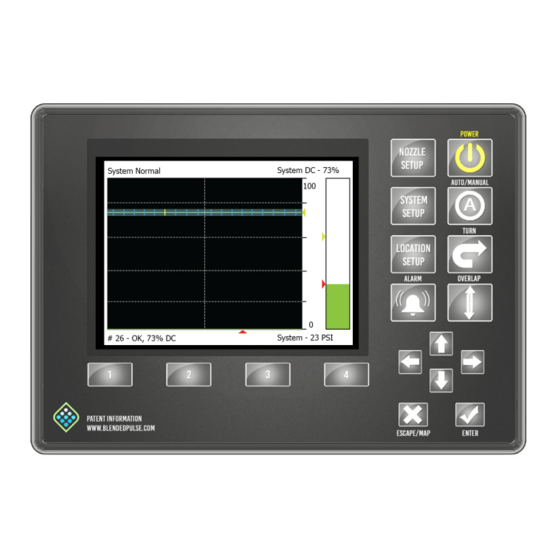
OPERATION OPERATION CAPVIEW BUTTON DESCRIPTIONS FIGURE 4: POWER button Press to turn on or off the CapView and the Gateway hub. AUTO/MANUAL button Press to change between Manual and Automatic operation mode TURN button Press to engage or disengage turn compensation OVERLAP button Press to engage or disengage overlap control Arrow buttons... -
Page 10: Start Up Procedure
OPERATION START UP PROCEDURE FIGURE 5: Before starting the machine engine, always make sure that the CapView and rate controller are off. 1. Start the machine engine. 2. Press the POWER button (1) to start the CapView and the rate controller. 3. -
Page 11: Nozzle Display
OPERATION FIGURE 8: For the N-Ject™ operation mode, the pressure will not automatically change. On the main operation screen, the pressure is represented in three ways: Green bar graph Yellow arrow P In value FIGURE 8 NOZZLE DISPLAY FIGURE 9: The duty cycle of each nozzle on the boom is indicated with a blue tick mark (1) on the scale. -
Page 12: Overlap Control
OPERATION OVERLAP CONTROL FIGURE 10: Press the OVERLAP button (1) to turn the overlap control on or off. Overlap can be turned off for situations that can include: • Spraying rinse water • Troubleshooting • No GPS signal • Other FIGURE 10 ©2017 Capstan Ag Systems Inc. -
Page 13: Mapping
OPERATION MAPPING Maps can be deleted, moved, copied, etc. Maps are stored in bitmap format and can be viewed with MS-Paint or a similar picture viewer program. A new map is started when the CapView is turned on and the OVERLAP button is selected. The system establishes a map origin and must stay within a 3-mile radius of the origin point. -
Page 14: Overlap Distance
OPERATION OVERLAP DISTANCE The PinPoint™ II system uses 1-meter-squares to record where spraying has occurred. Any spraying nozzle that touches one of these squares will cause the system to consider this as an area that has been sprayed. As the machine travels along, each nozzle looks to see if the approaching square has been sprayed or not. -
Page 15: Turn Compensation
If you need more information about turn compensation, contact your CapstanAG field representative or your servicing dealer. FIGURE 15: Press the TURN button (1) to turn on and off the turn compensation feature. -
Page 16: Counters
OPERATION COUNTERS FIGURE 17: The counters are shown on the System Setup screen. FIGURE 17 Gallon Counters The PinPoint™ II system manages the flow meter signal to keep the rate controller accurate when the N-Ject™ system is turned off. It is important to show the amount of manipulating that has occurred. -
Page 17: Vent And Drain The N-Ject™ System
OPERATION VENT AND DRAIN THE N-JECT™ SYSTEM IMPORTANT: This procedure must be done before any service or maintenance is performed on the N-Ject™ system. 1. Close the tank manual shutoff valve. 2. Pull the application knifes through the soil. 3. Turn on the N-Ject™ system and the section and master switches to apply ammonia. •... - Page 18 OPERATION NOTES ©2017 Capstan Ag Systems Inc. | PinPoint™ II for N-Ject™ NH3 Operator and Maintenance Manual...
-
Page 19: Maintenance
Maintenance MAINTENANCE SERVICE THE SYSTEM Before operation or service to the system, read and understand the machine’s operator manual and the PinPoint™ II for N-Ject™ NH3 operator and maintenance manual. Chemical residue may be present on/in the OEM equipment. Use the correct personal protective equipment. CLEAN THE SYSTEM Thoroughly clean the system after each use. -
Page 20: Clean The Y-Strainer
Maintenance CLEAN THE Y-STRAINER FIGURE 18: Remove the plug (1), magnet (2), and: screen (3). Clean the debris from the magnet and screen by washing with a solution that will remove an oily residue. Clean the strainers on a regular basis. Install the screen, magnet, and plug before operation. -
Page 21: Nozzle Valves
Maintenance NOZZLE VALVES The nozzle valves are on the N-Ject™ manifold(s). Nozzle valve assemblies are offered with a 7-watt coil with either a 1/16 inch or 3/32 inch orifice or a 12-watt coil with a 5/32 inch orifice. The 1/16 inch or 3/32 inch orifice for low flow applications or a 5/32 inch orifice for high flow applications. -
Page 22: Inspect The Plunger Seal
Maintenance Inspect the Plunger Seal FIGURE 22: After extended use, the Teflon plunger seal will wear a groove (1) where the seal impacts the hard orifice seat. Replace the plunger if worn or damaged. As the groove deepens the pressure capacity of the valve will decrease until the pressure capacity interferes with the operating pressure of the N-Ject™... -
Page 23: Troubleshooting
TROUBLESHOOTING TROUBLESHOOTING CAPVIEW SYSTEM ERROR CHART SYSTEM ERROR CAUSE CORRECTION System normal This indicates that the system is operating correctly Missing Gateway hub Communication to the Gateway hub Check the connections (key switch power, ignition, has been lost and battery power) and then cycle power to the system Missing VCM Communication to the VCMs has... -
Page 24: Over And Under Application
TROUBLESHOOTING CAPVIEW SYSTEM ERROR CHART SYSTEM ERROR CAUSE CORRECTION Valve lodges closed Debris in the valve Clean the valve Coil circuit open Coil wire is pinched, cut, or broke. Coil Check the coil connection and resistance (7-watt is disconnected coils - 21 ohms to 23.5 ohms/12-watt coils - 10 ohms to 11.5 ohms) Coil circuit closed Coil wire is pinched, cur, or broke. - Page 25 TROUBLESHOOTING OVER AND UNDER APPLICATION PROBLEM CAUSE CORRECTION Rate instability Low voltage to the rate controller Test the voltage and repair as needed Faulty speed sensor reading Check the radar and replace as needed Collapsed suction hose Replace the suction hose Inlet plugged Check and clean the inlet Incorrect valve calibration settings...
-
Page 26: Rate Controller - Under Application
TROUBLESHOOTING OVER AND UNDER APPLICATION PROBLEM CAUSE CORRECTION Skips at the edges of a Overlap distance is set too low Increase the overlap distance to at least 40 in field Incorrect GPS antenna location Check the measurements to the GPS antenna location CapView overlap settings are Set the look ahead time and overlap distance to... -
Page 27: Liquid Level Sensor Alarm
TROUBLESHOOTING RATE CONTROLLER - RATE INSTABILITY CAUSE CORRECTION Plugged, kinked, or collapsed hoses Check all hoses and replace as needed LIQUID LEVEL SENSOR ALARM CAUSE CORRECTION Tank is empty Fill the tank Slow ground speed Strainers are plugged, bad tank, or blockage in hose plumbing PinPoint™... -
Page 28: Recommended Guidelines
TROUBLESHOOTING RECOMMENDED GUIDELINES When servicing a system, CapstanAG recommends doing this three step troubleshooting process: 1. Perform baseline service checks and m the original system setup values in this manual. 2. Identify individual performance problems. Evaluate possible causes and corrections for performance issues. -
Page 29: Fuses
Coil failures are often the result of two factors: Extended valve use with a plugged nozzle. Extended use in corrosive environments. NOTE: CapstanAG recommends cleaning any plugged nozzle valves immediately. Use a voltmeter to measure the ohms of resistance across pins A and B on the nozzle valve connector. -
Page 30: Circuit Breaker
TROUBLESHOOTING CIRCUIT BREAKER FIGURE 25: A circuit breaker is located near the battery or in the battery box. The 80 A circuit breaker has an automatic/manual trip button (1) and a manual reset lever (2). A tripped circuit breaker (3) is an indicator of a short or overload condition. -
Page 31: Check The System Load Capacity
TROUBLESHOOTING CHECK THE SYSTEM LOAD CAPACITY 1. Start the engine of the machine. 2. Turn on the CapView and all of the boom sections. 3. Turn on all of the electrical loads, including the air conditioning, foam marker monitors, etc. 4. - Page 32 TROUBLESHOOTING FIGURE 30: Gateway Hub SERIAL PIN NUMBER DESCRIPTION RS232 Tx1 RS232 Rx1 Program DTR Program RTS Speed 1 Speed 2 12 V Key Switched DIGITAL PIN NUMBER DESCRIPTION ISO CAN High ISO CAN Low 12 V Key Switched Float Switch IN Backup Alarm IN Digital OUT FIGURE 30...
- Page 33 TROUBLESHOOTING SERVO BOOM SECTION 1 TO 6 PIN NUMBER DESCRIPTION WIRE PIN NUMBER DESCRIPTION COLOR Boom Section 1 (12 V On/0 V Off) Black Boom Section 2 (12 V On/0 V Off) Black Boom Section 3 (12 V On/0 V Off) Servo Output DEC Yellow Boom Section 4 (12 V On/0 V Off)
-
Page 34: Check The Vcm Voltage
TROUBLESHOOTING CHECK THE VCM VOLTAGE FIGURE 31: Disconnect the VCM extension harness (6-pin Deutsch connector) at each boom section VCM. • With the engine of the machine running, use a voltmeter to observe that there is a 13.5 VDC between pin 1 and pin 2. •... -
Page 35: Test The Pressure Sensor Signal
TROUBLESHOOTING TEST THE PRESSURE SENSOR SIGNAL FIGURE 33 FIGURE 33: Disconnect the pressure sensor (1) from the pressure sensor harness (2). Connect one end of the pressure sensor breakout harness diagnostic tool (3) into the pressure sensor shroud connector. Connect the other end to the connector for the pressure sensor harness tower. -
Page 36: Check The Power To The Pressure Sensor Input
TROUBLESHOOTING CHECK THE POWER TO THE PRESSURE SENSOR INPUT FIGURE 34 FIGURE 34: Disconnect the pressure sensor (1) from the pressure sensor harness (2). Connect one end of the pressure sensor breakout harness diagnostic tool (3) into the pressure sensor shroud connector. Connect the other end to the connector for the pressure sensor harness tower. -
Page 37: Liquid Level Sensor
TROUBLESHOOTING LIQUID LEVEL SENSOR FIGURE 35: The liquid level sensor has three LED lights: Green - Power (12 V) Purple - Liquid Level Sensor 1 Orange - Liquid Level Sensor 2 When the green LED illuminates, there is power to the system. - Page 38 TROUBLESHOOTING NOTES ©2017 Capstan Ag Systems Inc.| PinPoint™ II for N-Ject™ NH3 Operator and Maintenance Manual...
-
Page 39: Warranty
Warranty WARRANTY LIMITED WARRANTY Rev Date: 7/15/2014 A. What does the Limited Warranty cover? The ultimate purchaser/user (“you”), by acceptance of seller Capstan Ag Systems, Inc.’s, (“our,” “we,” or “us”) product, assume all risk and liability of the consequences of any use or misuse by you, your employees, or others. All replacement components furnished under this warranty, but shipped before the failed component is returned for evaluation, will be invoiced in the usual manner and warranty adjustments will be made after the component claimed to be defective has been returned to and inspected and deemed defective by us at our factory. - Page 40 Warranty B. What is the period of coverage? We warrant to you, that our products are free from defects in material and workmanship in normal use and service for a period of one year from date of purchase. C. How do you get service? Our obligation under this warranty shall be limited to the repairing or replacing at our option, the component which our inspection discloses to be defective, free of charge, return freight paid by us, provided you: (i) Notify us of defect within thirty (30) days of failure;...
-
Page 41: Schematics
SCHEMATICS SCHEMATICS MANIFOLD SCHEMATICS N-JECT™ MANIFOLD ITEM PART NUMBER DESCRIPTION 620100-001 Inlet Flange 620101-001 End Flange 620104-002 Master Slice 620106-001 Mounting Bracket 620110-001 1/2-20 Grade 8 Nut 620111-001 M12 Flat Washer 620186-001 1/2-13 x 1-1/4 in Grade 8 Bolt 620118-001 Strainer - 100-Mesh 620136-001 2-1/4 in ACME Fitting... - Page 42 SCHEMATICS N-JECT™ MANIFOLD 1013 1015 1113 1115 1215 1313 1413 1415 1515 1613 1615 1715 1813 1815 1913 1915 2013 2015 ITEM PART NUMBER DESCRIPTION 620103-002 Dual Port Slice 620112-001 O-Ring, 4mm x 136mm, Buna-N 620109-004 Threaded Rod 1/2-20 x 13 620109-006 Threaded Rod 1/2-20 x 16 620109-007...
- Page 43 SCHEMATICS FIGURE 36 FIGURE 36: Manifold PinPoint™ II for N-Ject™ NH3 Operator and Maintenance Manual | ©2017 Capstan Ag Systems Inc.
- Page 44 SCHEMATICS NOTES ©2017 Capstan Ag Systems Inc. | PinPoint™ II for N-Ject™ NH3 Operator and Maintenance Manual...
-
Page 45: Installation And Setup
Installation and Setup INSTALLATION AND SETUP Before operation or service to the system, read and understand the machine’s operator manual and the PinPoint™ II N-Ject™ NH3 operator and maintenance manual. Chemical residue may be present on/in the OEM equipment. Use the correct personal protective equipment. IMPORTANT: Before installation make sure that all parts are included in the shipping boxes. -
Page 46: Install The Pressure Sensor
Installation and Setup Install The Pressure Sensor FIGURE 37: 1. Install the inlet pressure sensor (1) as shown. The inlet pressure sensor is 0 psi to 250 psi. 2. Install the outlet pressure sensor (2) as shown. The outlet pressure sensor is 0 psi to 50 psi. IMPORTANT: Do not over-tighten the pressure sensor during installation. -
Page 47: Splitter Installation (Optional)
Installation and Setup Splitter Installation (Optional) FIGURE 40: If desired, a splitter can be installed to connect two rows to one manifold port. In this scenario, label the splitter by the row number rather than the N-Ject™ manifold. Row location 1 would be referenced as 1A and 1B or as 1 and 2. -
Page 48: Install The Vcms
Installation and Setup INSTALL THE VCMS 1. Locate the VCMs adjacent to the first nozzle on the associated boom section. The VCMs are tagged and marked for the appropriate boom sections (1 to 12, etc.) in VCM serial number order. 2. -
Page 49: Install The Boom Shutoff Adapter
Installation and Setup INSTALL THE BOOM SHUTOFF ADAPTER FIGURE 44: Connect a boom shutoff adapter to the BOOM 1-6 port (1) and BOOM 7-12 port (2) on the Gateway hub. FIGURE 44 INSTALL THE LIQUID LEVEL SENSOR (OPTIONAL) FIGURE 45: Install the liquid level sensor into the manifold. -
Page 50: Install The Extension Harness
Installation and Setup Install the Extension Harness FIGURE 47: Install the extension harness. PART NUMBER DESCRIPTION 620202-016 Extension Harness - 15 ft 620202-017 Extension Harness - 25 ft FIGURE 47 Install the Liquid Level Sensor Adapter FIGURE 48: Install the liquid level sensor adapter. For a single manifold system, one adapter is necessary. -
Page 51: Install The Capview Extension Harness
Installation and Setup FIGURE 50: 6. Connect the switched power connector (1) and the GPS connector (2) to the back of the CapView. 7. Remove the screen protector from the CapView screen. FIGURE 50 Install the CapView Extension Harness FIGURE 51: 1. -
Page 52: Install The Power Disconnect Breaker Kit
Installation and Setup INSTALL THE POWER DISCONNECT BREAKER KIT FIGURE 53: A power disconnect breaker kit is available for applications when unhooking the battery power cable is not desired. 1. Disconnect the battery cables. 2. Cut and strip the cables at the desired disconnect location. -
Page 53: System Setup
Installation and Setup SYSTEM SETUP The system is set up at the factory. These steps are only required when modifications have been made during installation or if changes were made to the machine after the PinPoint™ II order was placed. 1. -
Page 54: Location Setup Procedure
Installation and Setup FIGURE 56: 12. Use the left or right arrows (1) to select Yes (2). 13. Press the ENTER button (3). The CapView will turn off. Leave the key switch on to keep power to the hub. 14. Press the POWER button (4). A warning screen will show after a factory reset or when no data is present in the VCMs. -
Page 55: Location Setup Table
Installation and Setup FIGURE 59: The screen will give the option YES (to save) or NO (not to save) the entered data. 6. If the data is correct, use the right or left arrow buttons to select YES (1). 7. Press the ENTER button (2). A blue save bar will show and move across the screen. -
Page 56: Auto Location Setup
Installation and Setup AUTO LOCATION SETUP FIGURE 61: 1. Use the up or down arrow buttons (1) to set the desired nozzle spacing. The default setting is 20 inches. 2. Press the ENTER button (2). FIGURE 61 FIGURE 62: This screen shows a picture of the sprayer with the VCMs located on the boom. -
Page 57: System Setup
Installation and Setup 11. Engage each boom section control switch to correlate the boom valves to the VCMs. Engage switch #1, then #2, then #3, etc., from left to right so that #1 is the left most boom. The highlighter shows the VCM that is physically associated with that boom section switch. - Page 58 Enabled Press ENTER to change. If the PinPoint™ II system is not using nozzles that use the CapstanAG nozzle diagnostics properly, the nozzle diagnostics can be disabled here. CapstanAG uses this feature on demonstration units and development units where lights are substituted for valves or reset to coil only.
- Page 59 60 Inches Press Enter to change. CapstanAG has coined the term “Cat Whiskers” to describe this feature. Each nozzle has five imaginary cat whiskers by which it checks and marks the overlap map. There is a whisker in front, behind, right, left, and center. The center whisker marks the map as being sprayed. The other four whiskers are for checking if the nozzle needs to be turned off at an already sprayed area.
-
Page 60: Advanced Settings - N-Ject™ Operation Mode
Installation and Setup SYSTEM SETUP LINE LINE TITLE DEFAULT SETTING ACTION NUMBER DESCRIPTION Language English Press ENTER to change. Select the desired language: English or Portuguese Previous Error List Press ENTER to see. This displays the 50 most recent errors. Advanced Settings Press ENTER to change. - Page 61 Installation and Setup ADVANCED SETTINGS LINE LINE TITLE DEFAULT SETTING ACTION NUMBER DESCRIPTION GPS - Ant. Right of Center 0 Inches Press ENTER to change. Enter the number of inches that the GPS antenna is off-center. A positive number indicates that the antenna is right of center.
- Page 62 Nozzle Pulse Frequency 3.0 Pulse/Sec. Press ENTER to change. All CapstanAG systems run at 10 pulses per second pulse frequency. To run a faster pulse frequency, enter a larger number. CapstanAG does not recommend pulse frequencies slower than 10Hz in sprayer applications.
- Page 63 If major components are changed, a factory reset may need to be performed. Contact Information Selecting this line will open up a page with the CapstanAG toll-free phone number, website, and a QRC code that will direct you to the website.
-
Page 64: Nozzle Setup Procedure
Installation and Setup NOZZLE SETUP PROCEDURE 1. Press the NOZZLE SETUP button (1). FIGURE 63: Nozzle Setup is to set up each individual nozzle for: • Rank • Flow value • Nozzle size • Valve size • Auxiliary boom attachment •... -
Page 65: System Dry Test
Installation and Setup SYSTEM DRY TEST Do this procedure to make sure that the soft boom and nozzle valves are operating correctly. Boom Shutoff Dry Test 1. Make sure that the engine is off and the key is on. 2. Turn on the CapView display and the rate controller. 3. -
Page 66: Look Ahead Time And Overlap Test
Installation and Setup LOOK AHEAD TIME AND OVERLAP TEST The look ahead time and the overlap test show how the system is tuned to the speed of the GPS sensor and the time that it takes for overlap messages to make it to the nozzle valves. The look ahead time can be set with the help of two people to watch the nozzle valves at a known overlap point. -
Page 67: Compass Calibration
Installation and Setup COMPASS CALIBRATION The compass calibration is not required if the Gateway hub is installed in standard vertical orientation. In typical installations the compass is disabled; however, by selecting Compass (w/Turn) as a Forward/Reverse Detection Method in the SYSTEM SETUP, the 3-Dimensional compass can be used for forward/reverse detection and for low-speed turn compensation stability. -
Page 68: Setting The Gps Settings
Installation and Setup SETTING THE GPS SETTINGS FIGURE 67 FIGURE 67: Before operation make sure that the GPS setting values are correct. Measure and record the values for: • Antenna Ahead of the Rear Axle (A) • Inches from the rear axle centerline to the GPS antenna centerline. A positive number indicates the antenna is ahead of the rear axle. - Page 69 Installation and Setup FIGURE 68: 1. Press the SYSTEM SETUP button (1). 2. Use the up or down arrow buttons (2) to select GPS-Ant. Ahead of Rear Axle (3). 3. Enter the number of inches from the rear axle centerline to the GPS antenna centerline. This value is used for GPS overlap control to shut off nozzles in the proper place.
-
Page 70: Machine Specific Information
Installation and Setup MACHINE SPECIFIC INFORMATION Location Setup Information Machine Type: VCM Orientation Left Right Boom Section #1 Left VCM SN: Nozzle Qty. Right VCM SN: Nozzle Qty. Move these nozzles to Boom #2: Boom Section #2 Left VCM SN: Nozzle Qty. - Page 71 Installation and Setup Machine Type: VCM Orientation Left Right Boom Section #9 Left VCM SN: Nozzle Qty. Right VCM SN: Nozzle Qty. Move these nozzles to Soft Boom #8: Move these nozzles to Soft Boom #10: Boom Section #10 Left VCM SN: Nozzle Qty.
-
Page 72: System Setup Information
Installation and Setup System Setup Information Line Number Line Name Default Setting Actual Setting Operation Mode N-Ject™ Controller Gallon Counter 0 Gallons Actual Gallon Counter 0 Gallons Controller Acre Counter 0 Acres Actual Acre Counter 0 Acres Controller Gallons Per Minute 0.0 GPM Actual Gallons Per Minute 0.0 GPM... -
Page 73: Advanced System Setup Information - N-Ject™ Operation Mode
Installation and Setup Advanced System Setup Information - N-Ject™ Operation Mode Line Number Line Name Default Setting Actual Setting Hour Meter 0.0 Hours Compass Heading 0 Degrees Compass Offset 0 Degrees USB Mode Thumb Drive Total Number Valve Expected 0 Valves Scrolling Enable/Disable Enabled GPS - Antenna Ahead Of Rear Axle... - Page 74 Installation and Setup NOTES ©2017 Capstan Ag Systems Inc. | PinPoint™ II for N-Ject™ NH3 Operator and Maintenance Manual...
-
Page 75: Index
INDEX INDEX Clean ..............16 Inspect the Spray System ........15 Acre Counters ............12 Install the Battery Harness ........47 Advanced Settings ..........56 Install the Boom Shutoff Adapter ......45 Advanced System Setup Information ...... 69 Install the CapView ..........46 Alarm ............... - Page 76 INDEX Personal Protective Equipment ......... 2 Plunger Seal Inspect ..............18 Pressurized Fluid Lines ..........2 Rate Controller - Over Application ......22 Rate Controller - Rate Instability ....... 22, 23 Rate Controller - Under Application ......22 Recommended Troubleshooting Guidelines ... 24 Reset the Counters ..........
- Page 77 INDEX PinPoint™ II for N-Ject™ NH3 Operator and Maintenance Manual | ©2017 Capstan Ag Systems Inc.
- Page 78 APPLICATION SYSTEMS FOR PROFESSIONALS™ P/N 122200-240 Rev. B | Revised 07/2017 | ©2016-2017 Capstan Ag Systems, Inc. All Rights Reserved.
Need help?
Do you have a question about the PinPoint II and is the answer not in the manual?
Questions and answers