
Related Manuals for Agilent Technologies Turbo-V


Summary of Contents for Agilent Technologies Turbo-V
- Page 1 Turbo-V Vent Valve Model 969-9843 Manuale di Istruzioni Bedienungshandbuch Notice de Mode D’Emploi User Manual 87-900-947-01 (F) 04/ 2011...
- Page 2 Do not “Restricted computer software” as proceed beyond a WARNING notice defined in FAR 52.227-19 (June 1987) until the indicated conditions are or any equivalent agency regulation or fully understood and met. Turbo-V Vent Valve User Manual / 87-900-947-01 (F)
- Page 3 Turbo-V Vent Valve Turbo-V Vent Valve Turbo-V Vent Valve 87-900-947-01 (F) User Manual 3/44...
- Page 4 Turbo-V Vent Valve 4/44 Turbo-V Vent Valve User Manual / 87-900-947-01 (F)
-
Page 5: Table Of Contents
17 Installation 19 Entsorgung 22 Procédure pour l’installation 23 Généralités 24 Caractéristiques techniques 25 Installation 27 Mise au Rebut 30 Installation procedure 31 Overview 32 Technical characteristics 33 Installation 35 Disposal 38 Turbo-V Vent Valve 87-900-947-01 (F) User Manual 5/44... - Page 6 Contents 6/44 Turbo-V Vent Valve User Manual / 87-900-947-01 (F)
-
Page 7: Procedura Per L'installazione
Turbo-V Vent Valve User Manual Procedura per l’installazione Generalità Caratteristiche tecniche Unità di controllo 9 Cavi di connessione Vent valve Installazione Smaltimento Traduzione delle istruzioni originali 7/44... -
Page 8: Generalità
Il Turbo-V “Vent Valve” comprende un’unità di controllo ed una valvola, che realizzano un sistema completo per la ventilazione automatica della pompa Turbo-V nella fase di spegnimento o nel caso si verifichi una caduta di tensione. La valvola in condizioni di riposo (senza alimentazione) è... -
Page 9: Caratteristiche Tecniche
Temperatura di da -20 a 50 °C immagazzinamento Cavi di connessione Ingresso lungo 0,5 metri, 3 fili Uscita alla valvola lungo 5 metri, 3 fili Peso (con cavo): 0,5 Kg (1,1 lbs) Turbo-V Vent Valve 87-900-947-01 (F) User Manual 9/44... -
Page 10: Vent Valve
24 Vcc +10% -5% - potenza 2,5 W Temperatura di bakeout 60 °C Peso (senza cavo) 0,1 Kg (0,24 lb) La figura seguente riporta le dimensioni di ingombro del Turbo-V Vent Valve. LUNGHEZZA CAVO 5000 [197] LUNGHEZZA [2,95] CAVO 1000 [39,3]... -
Page 11: Installazione
Installazione Installazione Installazione In figura sono riportati i vari componenti presenti nel Kit Turbo-V In figura sono riportati i vari componenti presenti nel Kit Turbo-V Vent Valve. Tali componenti sono forniti disassemblati; sarà quindi Vent Valve. Tali componenti sono forniti disassemblati; sarà quindi cura del cliente provvedere all’assemblaggio del Kit. - Page 12 CAVO DI ALIMENTAZIONE Figura 3 Installazione su pompa con tappo a vite Dopo aver completato l’installazione meccanica, collegare il cavo di alimentazione dell’unità di controllo del Turbo-V vent valve al rispettivo connettore sul pannello posteriore del governo del Turbo pump. 12/44...
- Page 13 Se si esegue l’installazione su una pompa il cui governo non dispone della presa di alimentazione valvola a 115 Vca, occorre rimuovere il connettore tagliando il cavo di alimentazione del governo; quindi collegarlo al modulo J21 come riportato nella figura precedente. Turbo-V Vent Valve 87-900-947-01 (F) User Manual 13/44...
-
Page 14: Smaltimento
14/44 Turbo-V Vent Valve User Manual / 87-900-947-01 (F) -
Page 15: Anleitung Zur Installation
Turbo-V Vent Valve User Manual Anleitung zur Installation Allgemeines Technische Daten 17 Steuereinheit 17 Anschlusskabel Vent valve Technische Daten 17 Entsorgung Übersetzung der Originalanleitungen 15/44... -
Page 16: Allgemeines
Am Eingang des Ventils ist ein Filter oder Adapter Größe 1/4” vorhanden, der die einströmende Luft filtert. Die Steuereinheit wird von der Turbo-V - Steuerung versorgt, die nicht zur Montage auf dem Rack vorgesehen ist. Die Steuereinheit wird mit einer auf zirka 2,5 Sekunden voreingestellten Verzögerung eingeschaltet, um eine unerwünschte... -
Page 17: Technische Daten
0 bis 40 °C Lagerungstemperatur von -20 bis 50 °C Anschlusskabel Eingang Länge = 0,5 m, 3 Adern Ausgang zum Ventil Länge = 5 m, 3 Adern Gewicht (mit Kabel) 0,5 Kg (1,1 lbs) Turbo-V Vent Valve 87-900-947-01 (F) User Manual 17/44... - Page 18 0,1 Kg (0,24 lb) Auf nachstehender Abbildung sind die Abmessungen des Ventils Turbo-V Vent Valve angegeben. KABELLÄNGE 5000 [197] KABELLÄNGE 1000 [39,3] [2,95] 75 [2,95] Abbildung 1 Maße in mm [Zoll] 18/44 Turbo-V Vent Valve User Manual / 87-900-947-01 (F)
-
Page 19: Installation
In der Abbildung sind die verschiedenen Bauteile der Baugruppe In der Abbildung sind die verschiedenen Bauteile der Baugruppe Turbo-V Vent Valve dargestellt. Diese Bauteile werden lose geliefert Turbo-V Vent Valve dargestellt. Diese Bauteile werden lose geliefert und müssen daher vom Kunden zusammengebaut werden. - Page 20 Abbildung 3 Installation auf Pumpe mit Verschlussschraube Nach erfolgter mechanischer Installation das Verbindungskabel der Steuereinheit des "Heavy Duty Vent Valve" an den Stecker an der hinteren Platte der Steuerung der Turbopumpe anschließen. 20/44 Turbo-V Vent Valve User Manual / 87-900-947-01 (F)
- Page 21 Steuerung über keinen Anschluß 115 V a.c. zur Ventilversorgung verfügt, muß der Stecker entfernt werden, indem das Versorgungskabel der Steuereinheit durchgeschnitten und an das Modul J21 angeschlossen wird, wie in obiger Abbildung dargestellt. Turbo-V Vent Valve 87-900-947-01 (F) User Manual 21/44...
-
Page 22: Entsorgung
Sammelsystem zugeführt werden muss. Der Endabnehmer sollte daher den Lieferanten des Geräts - d.h. die Muttergesellschaft oder den Wiederverkäufer - kontaktieren, um den Entsorgungsprozess zu starten, nachdem er die Verkaufsbedingungen geprüft hat. 22/44 Turbo-V Vent Valve User Manual / 87-900-947-01 (F) -
Page 23: Procédure Pour L'installation
Turbo-V Vent Valve User Manual Procédure pour l’installation Généralités Caractéristiques techniques Système de commande 25 Câbles de connexion Vent Valve Installation Mise au Rebut Traduction de la mode d’emploi originale 23/44... -
Page 24: Généralités
1/4” pour tuyaux présent sur l’entrée d’air de la valve elle-même. Le système de commande est alimenté par le gérant Turbo-V qui n’est pas prédisposé pour être monté sur rack. -
Page 25: Caractéristiques Techniques
-20 à 50 °C stockage Câbles de connexion Entrée 0,5 mètres de long, 3 fils Sorties à la valve 5 mètre de long, 3 fils Poids (avec câble) 0,5 Kg (1,1 lbs) Turbo-V Vent Valve 87-900-947-01 (F) User Manual 25/44... -
Page 26: Vent Valve
0,1 Kg (0,24 lb) La figure ci-dessous indique les dimensions d’encombrement du Turbo-V Vent Valve. LONGUEUR CABLE 5000 [197] LONGUEUR CABLE [2,95] 1000 [39,3] 75 [2,95] Figure 1 Dimensions en mm (pouces) 26/44 Turbo-V Vent Valve User Manual / 87-900-947-01 (F) -
Page 27: Installation
La figure illustre les différents composants présents dans le kit La figure illustre les différents composants présents dans le kit Turbo-V Vent Valve. Ces composants sont fournis démontés; il faudra Turbo-V Vent Valve. Ces composants sont fournis démontés; il faudra donc que le client fasse l’assemblage du kit. - Page 28 D’ALIMENTATION Figure 3 Installation sur pompe avec bouchon à vis Après avoir achevé l’installation mécanique, brancher le câble d’alimentation du système de commande du Turbo-V Vent Valve à son connecteur sur le panneau arrière du gérant du Turbo pump. 28/44...
- Page 29 à 115 Vac, il faut enlever le connecteur en coupant le câble d’alimentation du gérant; puis le brancher au module J21 ainsi que sur la figure ci-dessus. Turbo-V Vent Valve 87-900-947-01 (F) User Manual 29/44...
-
Page 30: Mise Au Rebut
Après avoir vérifié les termes et conditions du contrat de vente, l’utilisateur final est donc prié de contacter le fournisseur du dispositif, maison mère ou revendeur, pour mettre en oeuvre le processus de collecte et mise au rebut. 30/44 Turbo-V Vent Valve User Manual / 87-900-947-01 (F) -
Page 31: Installation Procedure
Turbo-V Vent Valve User Manual Installation procedure Overview Technical characteristics Control unit Connection Cables 33 Vent Valve Installation Disposal Original Instructions 31/44... -
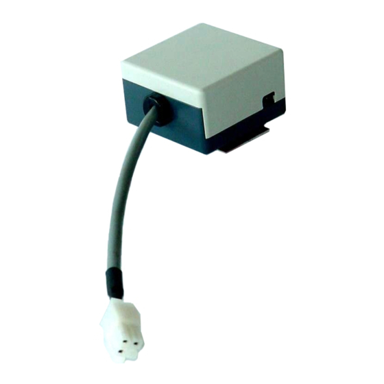
Page 32: Overview
Overview Overview The Turbo-V “Vent Valve”, consisting of a control unit and a valve, is a complete unit for automatic venting of the Turbo-V vent pump when it is switched off or during a power failure. The valve is a... -
Page 33: Technical Characteristics
0 to 40 °C Storage temperature -20 to 50 °C Connection Cables Input 0.5 meter long, 3 wire Output to valve 5 meters long, 3 wire Weight (with cable) 0.5 Kg (1.1 lbs) Turbo-V Vent Valve 87-900-947-01 (F) User Manual 33/44... -
Page 34: Vent Valve
24 Vdc +10% -5% - power 2.5 W Bakeout temperature 60 °C Weight (w/o cable) 0.1 Kg (0.24 lb) The following figure gives the overall dimensions of the Turbo-V Vent Valve. CABLE LENGTH 5000 [197] CABLE LENGTH [2.95] 1000 [39.3] 75 [2.95]... -
Page 35: Installation
Installation Installation Installation The following figure shows the different components of the Turbo-V The following figure shows the different components of the Turbo-V Vent Valve kit. These will be supplied to the client disassembled. Vent Valve kit. These will be supplied to the client disassembled. - Page 36 POWER CORD Figure 3 Installation on a Pump Equipped with a Screw Cap Upon completion of the mechanical installation, attach the Turbo-V vent valve controller unit power cord to the related connector on the rear panel of the Turbo pump controller.
- Page 37 For installation on a pump whose controller is not equipped with a 115 Vac valve power supply socket, remove the connector after cutting the controller power cord and connect it to module J21 as shown in the previous figure. Turbo-V Vent Valve 87-900-947-01 (F) User Manual 37/44...
-
Page 38: Disposal
The end user is therefore invited to contact the supplier of the device, whether the Parent Company or a retailer, to initiate the collection and disposal process after checking the contractual terms and conditions of sale. 38/44 Turbo-V Vent Valve User Manual / 87-900-947-01 (F) - Page 44 Request for Return Form Sales and Service Offices United States India Southeast Asia Agilent Technologies Agilent Technologies India Pvt. Ltd. Agilent Technologies Sales Sdn Bhd Vacuum Products Division Vacuum Product Division Vacuum Products Division 121 Hartwell Avenue G01. Prime corporate Park,...