Table of Contents
Advertisement
Quick Links
USER MANUAL
NI 9759
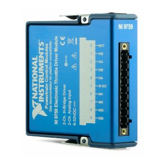
NI Powertrain Controls Electronic Throttle Driver Module
Contents
Introduction .............................................................................................................................. 2
Pinout........................................................................................................................................ 2
Hardware .................................................................................................................................. 3
Powering the Module................................................................................................................ 3
Platform Compatibility ............................................................................................................. 3
H-Bridge Drivers ...................................................................................................................... 4
Analog Inputs ........................................................................................................................... 5
Throttle Control ........................................................................................................................ 7
Compliance and Certifications ................................................................................................. 9
Physical Specifications and Characteristics ............................................................................. 11
Advertisement
Table of Contents

Related Manuals for National Instruments 9759


Summary of Contents for National Instruments 9759
-
Page 1: Table Of Contents
USER MANUAL NI 9759 NI Powertrain Controls Electronic Throttle Driver Module Contents Introduction ..........................2 Pinout............................2 Hardware ..........................3 Powering the Module........................ 3 Platform Compatibility ......................3 H-Bridge Drivers ........................4 Analog Inputs ........................... 5 Throttle Control ........................7 Compliance and Certifications .................... -
Page 2: Introduction
The NI 9759 includes a LabVIEW FPGA VI for controlling two H-Bridge driver channels independently and a set of RT VIs which allow the user to calibrate the throttle control algorithm in engineering units. -
Page 3: Hardware
The external screw-terminal connector has terminals labeled BATT (0) and GND (9). Typical power sources will be from automotive 12 V or 24 V battery systems. The NI 9759 can accept power from a range of 7 V to 32 V. Without throttles connected, the module requires a maximum 100 mA from the external supply. -
Page 4: H-Bridge Drivers
70 mm in diameter. A typical example of electronic throttle bodies which the NI 9759 is capable of driving, is the Bosch DV-E5 series which range from 32 mm to 68 mm in diameter. The NI 9759 is capable of driving most other electronic throttle bodies within that size range. -
Page 5: Analog Inputs
Analog Inputs The NI 9759 provides two external analog inputs for accepting 0 V to 5 V signals. The primary purpose of these inputs is for measuring potentiometer voltages. A regulated 5 V output and ground terminal is provided for powering the potentiometer(s) of an electronic throttle body. - Page 6 Table 1 below shows the terminal connections to a standard Bosch DV-E5 electronic throttle body. Figure 2. Terminal Connections to a Single Electronic Throttle Body Figure 3. Terminal Connections to Dual Electronic Throttle Bodies 6 | ni.com | NI 9759 User Manual...
-
Page 7: Throttle Control
NI 9759. Throttle Control NI provides a flexible throttle position control algorithm with the NI 9759. Follow the throttle control example included in the driver package for implementing throttle control in your engine control application. Perform throttle control at a rate of 100 to 200 Hz, even if your engine control algorithms require execution at another rate, a separate timed loop can be created to implement throttle control. - Page 8 If this VI is used for position, a filter is not required. Begin control calibration with zero for all Lead/Lag, PID and compensation calibration parameters. Begin tuning PID gains for angles above ThetaLH. 8 | ni.com | NI 9759 User Manual...
-
Page 9: Compliance And Certifications
When operating this product, use shielded cables and accessories. CE Compliance This product meets the essential requirements of applicable European Directives as follows: • 2006/95/EC; Low-Voltage Directive (safety) • 2004/108/EC; Electromagnetic Compatibility Directive (EMC) NI 9759 User Manual | © National Instruments | 9... - Page 10 At the end of the product life cycle, all products must be sent to a WEEE recycling center. For more information about WEEE recycling centers, National Instruments WEEE initiatives, and compliance with WEEE Directive 2002/96/EC on Waste and Electronic Equipment, visit ni.com/environment/...
-
Page 11: Physical Specifications And Characteristics
Safety Guidelines Caution Do not operate the NI 9759 in a manner not specified in these operating instructions. Product misuse can result in a hazard. You can compromise the safety protection built into the product if the product is damaged in any way. If the product is damaged, return it to National Instruments for repair. - Page 12 NI product. Refer to the Export Compliance Information at ni.com/legal/export-compliance for the National Instruments global trade compliance policy and how to obtain relevant HTS codes, ECCNs, and other import/export data. © 2013 National Instruments. All rights reserved.
Need help?
Do you have a question about the 9759 and is the answer not in the manual?
Questions and answers