
Related Manuals for Tokyo Keiki UFP-20


Summary of Contents for Tokyo Keiki UFP-20
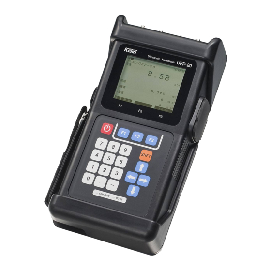
- Page 1 Doc No. KF08-002L Portable Ultrasonic Flowmeter UFP-20 Installation & Operation Manual...
-
Page 2: Ultrasonic Flowmeter Safety Precautions
Ultrasonic Flowmeter Safety Precautions The following safety precautions contain important information pertaining to the safe use of the Ultrasonic Flowmeter. Read this text carefully and follow the directions given herein at all times. In order to prevent injury and/or damage resulting from inappropriate use, carefully follow the instructions given in this Operation Manual when operating the equipment, and observe the caution markings and messages below. - Page 3 The attachment of warning label is as follows. Warning label Fig. 1-2 Rear view of main unit...
- Page 4 Usage Precautions This instrument is used to measure flow quantities by means of ultrasound. For safe usage and optimum performance of the flowmeter, always operate the instrument according to the usage precautions below. 1. Failure to comply with one or more of the following conditions may result in poor measurement performance or incorrect measurement values.
-
Page 5: Introduction
Introduction Thank you for purchasing our Ultrasonic Flowmeter. This Manual includes detailed explanations regarding safety cautions, structure, set up, operation, troubleshooting, and maintenance of the Ultrasonic Flowmeter. Read this manual carefully before operation to ensure an adequate understanding of the equipment. -
Page 6: Table Of Contents
Ultrasonic Flowmeter Safety Precautions ............... (1) Usage Precautions ..........…..........(3) Introduction ......................(4) Proper use of the Operation Manual ............... (4) Precautions regarding the Manual ................(4) Restrictions and precautions necessary to maintain the equipment ....... (4) INDEX 1. Installation Here you can see how to install flowmeter system. - Page 7 3. Other Here you can see concerned with Maintenance, Specification or Measuring Principle. 3.1 Maintenance and Inspections............3-1 3.1.1 Transducer and Main unit maintenance and inspection....3-1 3.1.2 Life of components................3-1 3.2 General Specifications..............3-3 3.2.1 Overall Specifications................ 3-3 3.2.2 Main unit specifications..............
-
Page 8: Installation
1. Installation... - Page 10 Chapter 1 INDEX 1.1 Configuration ....................... 1-1 (1) Components........................1-1 (2) Example of flowmeter or massmeter basic system....….……......1-5 (3) Example of heatmeter basic system..….…………............. 1-6 (4) Carrying case..............….…………......1-7 1.2 Installation and connections ................... 1-10 1.2.1 Overview for setup procedure..................1-10 (1) Procedure for first start-up...................
- Page 11 1.2.8 Input parameters for heatmeter................... 1-62 (1) Flow of installation wizard.................... 1-62 (2) Installation wizard for heatmeter with 1path/1pipe or 2path/1pipe....... 1-63 (3) Installation wizard for heatmeter with 1path/2pipe (2 channel) setting......1-77 1.2.9 Transducer installation....................1-79 (1) Installation for small transducer................... 1-79 (2) Installation for medium transducer (V-path method)............
- Page 12 1.1 Configuration (1) Components This Ultrasonic Flowmeter consists of the following primary components. Figure 1.1-1 to 1.1-4 shows the interrelationship among the different parts. Table 1.1-1 Primary components Name Q'ty Details Photo Ultrasonic flowmeter Main unit Main unit Battery Ni-MH battery AC adaptor AC adaptor for main unit Couplant...
- Page 13 Ultrasonic transmitter-receiver sensors (to be used in combination with cables) Metal fixtures used to attach transducers onto Medium pipe. transducers 1set Upper photo : transducer mounting 2nd photo : mounting fixture 1 fixture 3rd photo : mounting fixture 2 4th photo : Z-path method adaptor (Applicable diameter DN20mm~40mm) Carrying Carrying case for primary components...
- Page 14 Table 1.1-2 Transducer Options (Option) Name Q'ty Details Photo Connection cable for transducer and main unit Transducer Temperature range : -20 to 65 degree C cable Length : 7 m Ultrasonic transmitter-receiver sensors (to be used in combination with cables) Small transducers Metal fixtures used to attach transducers onto...
- Page 15 Carrying case Carrying case for small/medium Transducer Kit small/medium transducer Carrying case for large Carrying case for large Transducer Kit transducer Table 1.1-3 Temperature Options (Option) Name Q'ty Details Photo Temperature Temperature sensor Pt-100 (2pcs) 1pair sensor Length : 5 m Junction box for connection of 4pcs temperature Temperature sensor...
- Page 16 Thickness Sensor thickness & sound speed measurement gauge Length : 0.7 m Test piece Calibration test piece for above sensor (No.4) Cable for cigarette lighter port of automobile to Cigarette supply power to flowmeter lighter cable Length : 3 m...
- Page 19 (3) Example of heatmeter basic system Temperature sensor Return side Supply side Flow Temperature junction box Large transducer Transducer cable Analog devices 4-20mA analog output Analog output cable (Max. resistance 550 ohm) Main unit Fig. 1.1-3 Exp. heatmeter basic system (1 path and 2 path)
- Page 20 Temperature sensor Return side Temperature junction box Supply side Large Small transducer Supply side transducer Flow Flow Return side Transducer cable Analog devices Analog output cable 4-20mA analog output (Max. resistance 550 ohm) Main unit Fig. 1.1-4 Exp. heatmeter basic system (2 pipes)
-
Page 21: Overview For Setup Procedure
1. 2 Installation and connections When setting up the Ultrasonic Flowmeter, carefully consider the conditions stated below. 1. 2. 1 Overview for setup procedure (1) Procedure for first start-up The basic steps in starting up the flowmeter system are outlined below. Table 1.2.1-1 Setup items for first start-up Step Procedure... -
Page 22: Connection Ports & Display Indication Of Main Unit
1.2.2 Connection ports & display indication of the main unit (1) Setup location Consider the following conditions when selecting a setup location for the main unit. a. Place the main unit in a location with an ambient temperature range of -10 to +50 degree C. Do not place the unit near a heating element and avoid exposure to direct sunlight. - Page 23 (2) LCD indication & key panel assignment All icons and key arrangements are as follows. For detail, please refer to Table1 on next page. Bright / contrast adjustment USB connection Log mode Totalizing function DC power supply/battery Coupling mark for thickness R1 D1 E1 C H 1 : # 0 1 : 1 0 0 / S t e e l / 1 M Meter type indication...
- Page 24 Table 1.2.2-1 Connection terminals, indications and key functions Specification or settings may limit the functions. Please be careful of the polarization of each line. Icon on Name Connection Instruction display Connection to primary path transducers or thickness gauge. SENSOR1 LEMO Connect upstream transducers to "UP"...
-
Page 25: Procedure For Start Up
1.2.3 Procedure for start up (1) Remove the protection cover Prior to set battery, first protection cover must be taken out. Please follow bellow steps. Sleeve 1. Open hook and loop fastener. 2. Pull hand strap out from sleeve. 3. Pull the protection cover off form down 4. - Page 26 (2) Battery connection Open the cover of the battery and connect the battery cable. Unscrewed these 4 pcs 1. Loose 4pcs of screw by +screw driver. 2. Connect cable with care on polarization. Screw these 4 pcs 3. Fix. 4pcs of screw again. Fig.
- Page 27 (3) Restore the protection cover After connection of the battery, let the cover attach the main unit again. Please follow below steps. Be careful, not to be tucked with the wires. 1. Insert top side of the main unit to the 2.
- Page 28 (4) Battery Charge Open side cover, then connect AC adaptor. Please be noted that battery charging will not start during the main unit runs. RED LED on AC adaptor Open cover Fig. 1.2.3-4 Battery charge You can check GREEN LED when DC power supplied, also RED LED when charging started. Charging will be completed when RED LED turns off.
- Page 29 (5) Turn on the main unit Push power key about 3 seconds, then automatically self-check diagnostic will activate. After self check you can see, message as right for basic setting check. S E L F C H E C K S e r i a l N o .
- Page 30 (7) Time setting Under “System setting” directory, you can find date-time setting as below. Table 1.2.3-1 The items of time setting Items Selection Input YY-MM-DD format (default) by numeric button Date Time Input HH:MM:SS format by numeric button Select from following options for your local area by up/down button. “YY/MM/DD”, Date Format “MM/DD/YY”...
- Page 31 M e t e r S e l e c t i o n A v e r a g e T i m e 2 : M e t e r T y p e f l o w m e t e r 3 : M e a s .
-
Page 32: Connection Detail Of Main Unit Ports
1.2.4 Connection detail of main unit ports (1) Open connector [ Transducer Connection Port ] Connector must be In case of tight, pulled with lid as you can pull the photo on the left. wire instead. But normally we will not recommend this procedure. - Page 33 (3) Connection of extended cable 50 m extended cable can be connected with standard cable mixed as below. Extension cable (50m) Standard cable (7m) Fig. 1.2.4-3 Connection of extended cable (4) Temperature sensor connection Up to 4 pcs of temperature sensor can be through “temperature junction box” as below. Each temperature sensor should be connected proper port.
- Page 34 Fig. 1.2.4-6 Temperature junction box connector 5-b. Connection of RTD, Temperature junction box and the main unit Each wire of RTD should be connected and tightened by fine screw driver. Then connect the junction box with connection port of the main unit. RTD should be 3 wire type.
- Page 35 5-c. Attachment of RTD onto the pipe RTD will be attached by metal adhesive tape to be well touched onto the pipe as Fig.1.2.4-8. Fig. 1.2.4-8 Attachment of RTD (6) Thickness / sound speed measurement sensor connection Sensor should be connected to SENSOR 1 (DN1/UP1) port of transducer’s port. Sound speed Calibration done measurement...
- Page 36 Red tube side must be connected on + side. Fig. 1.2.4-11 Analog output cable (8) Cigarette lighter cable connection The cigarette lighter port of the automobile can supply power to the flowmeter by using the cigarette lighter cable of the option. Figure 1.2.4-12 shows the connection diagram of this cable.
-
Page 37: Selection Of Transducer Setup Position
1.2.5 Selection of transducer setup position (1) Setup position As a rule, compliance with the conditions given below when positioning the transducers assures top performance of the flowmeter and keeps measurement aberrations due to flow quantity fluctuation at an absolute minimum. a. - Page 38 a. Pipe should always be filled with water Measurements cannot be made accurately if pipe is not completely filled with water. Air Entrapped Flow Flow Open b. Sediment Sediment accumulation at the transducer position may cause measurement errors. Countermeasures include installation of closing flange, etc. Flow Sediment c.
-
Page 39: Input Parameters For Flowmeter
1.2.6 Input parameters for flowmeter (1) Flow of installation wizard Installation wizard archives easy parameters input of all required parameters through dialog type menu. Installation Wizard Select Filename Input Filename Diameter Pipe Condition Material Thickness Circumference Lining Condition Material Thickness Fluid Condition Type Sensor Condition... - Page 40 (2) Installation wizard for flowmeter with 1path/1pipe or 2path/1pipe This portable unit can be selectable from “flow meter”, “mass meter” and “heat meter”. Also “1path / 1pipe (1 location)”, “2path / 1pipe (1 location)” and “1path / 2 pipe (2 locations)” can be selected on each meter mode.
- Page 41 1. Select “Installation Wizard” on the basic menu Select “1:Installation Wizard” by direction or numeric button. Then push “Select” key (F3 button). M e n u I n s t a l l a t i o n W i z a r d 2 : <...
- Page 42 M e s s a g e D o n o t s e l e c t t h i s f i l e . Fig.1.2.6-4 Message of selection not used area 3. File name input Please input file name by direction button. Here for example, let’s input as “100/Steel/1M”.
- Page 43 S e l e c t F i l e n a m e # 0 1 : ! " # $ % & ' ( ) * + , - . / 2 3 4 5 6 7 8 9 : ; < = > ? A B C D E F G H I J K L M N O P Q R S T U V W X Y Z D e l e t e...
- Page 44 5. Finalizing file name By repeating procedure of 1-4, you can input “100/Carbon Steel/1M” as follows. After finalizing the file name, proceed next menu by move cursor “Enter” and push “Select” key (F3 button), otherwise [SHFT] + F3 button makes the same step taken. S e l e c t F i l e n a m e 1 0 0 / S t e e l / 1 M # 0 1 :...
- Page 45 Input diameter by numeric button directly. Here for example, input 114.30mm as right. Then push “Enter” key (F3 button) to proceed to next step. P i p e C o n d i t i o n D i a m e t e r 1 1 4 .
- Page 46 8. Thickness of pipe Input pipe thickness by numeric button directly. Here for example, input “4.50mm”, then push “Enter” key (F3 button) to proceed to next step. P i p e C o n d i t i o n T h i c k n e s s 4 .
- Page 47 10. Thickness of lining Input lining thickness by numeric button directly. Here for example, input “1.00mm”, then push “Enter” key (F3 button) to proceed to next step. L i n i n g C o n d i t i o n T h i c k n e s s 0 .
- Page 48 Table 1.2.6-4 Selectable items of fluid type Fluid Sound speed [m/s] Viscosity [x10 Water 1460 1.20 Sea Water 1510 1.00 Ethylene Glycol (50wt%) 1691 4.13 Glycerin 1923 1188.50 Acetone 1190 0.41 12. Transducer type Select transducer type from default choices by direction or numeric button. Here for example, select “2:UP10AST”, then push “Select”...
- Page 49 (a) Z-path method This type of method is effective for application of measurement on the larger pipe or measurement for attenuating fluid against ultrasonic. Because of transducers distance is relatively shorter, so please select this method when V-path method installation is impossible.
- Page 50 14. Flow rate unit setting Select flow rate unit from default choices by direction or numeric button. Here for example, select “3: m /h”, then push “Select” key (F3 button) to proceed next step. U n i t S e t t i n g F l o w U n i t 1 : m 1 1 : L / m i n...
- Page 51 16. Totalizing unit setting Select totalizing unit from default choices by direction or numeric button. Here for example, select “1: x1m ”, then push “Select” key (F3 button) to proceed next step. U n i t S e t t i n g F l o w T o t a l U n i t x 1 m 2 : x 5 m...
- Page 52 When select “2: Yes”, following message will be shown. M e s s a g e N o w s t o r i n g . Fig. 1.2.6-26 Data storing When select “1: No”, following message will be shown. Then again you select “Yes” (F1 button), site setting data will be discarded.
- Page 53 18. Mounting transducers The main unit calculates proper distance between transducers as following message. Then push “OK” (F3 button) to start measurement. Please set transducer mounting with indicated transducer distance in accordance with instruction on Chapter 1.2.9. On this example, distance of transducers is 63.8 mm. M e s s a g e M o u n t i n g I n f o r m a t i o n Distance...
- Page 54 (3) Installation wizard for flowmeter with 1path/2pipe (2-channel) setting This portable unit can be selectable from “flow meter”, “mass meter” and “heat meter”. Also “1path / 1pipe (1 location)”, “2path / 1pipe (1 location)” and “1path / 2 pipe (2 locations)” can be selected on each meter mode.
- Page 55 3. Store site data Finalize wizard by store all data on this menu. Select “2: Yes” by direction or numeric button. Then push “Select” to proceed next step. D A T A S t o r e 1 : N o Y e s Push Select...
-
Page 56: Input Parameters For Massmeter
1.2.7 Input parameters for massmeter (1) Flow of installation wizard Installation wizard archives easy parameters input of all required parameter through dialog type menu. Installation Wizard Select Filename Input Filename Diameter Pipe Condition Material Thickness Circumference Lining Condition Material Thickness Fluid Condition Type Sensor Condition... - Page 57 (2) Installation wizard for massmeter with 1path/1pipe or 2path/1pipe This portable unit can be selectable from “flow meter”, “mass meter” and “heat meter”. Also “1path / 1pipe (1 location)”, “2path / 1pipe (1 location)” and “1path / 2 pipe (2 locations)” can be selected on each meter mode.
- Page 58 1. Select “Installation Wizard” on the basic menu Select “1:Installation Wizard” by direction or numeric button. Then push “Select” key (F3 button). M e n u I n s t a l l a t i o n W i z a r d 2 : <...
- Page 59 M e s s a g e D o n o t s e l e c t t h i s f i l e . Fig.1.2.7-4 Message of selection not used area 3. File name input Please input file name by direction button. Here for example, let’s input as “100/Steel/1M”.
- Page 60 S e l e c t F i l e n a m e # 0 1 : ! " # $ % & ' ( ) * + , - . / 2 3 4 5 6 7 8 9 : ; < = > ? A B C D E F G H I J K L M N O P Q R S T U V W X Y Z D e l e t e...
- Page 61 5. Finalizing file name By repeating procedure of 1-4, you can input “100/Carbon Steel/1M” as follows. After finalizing the file name, proceed next menu by move cursor “Enter” and push "Select" key (F3 button), otherwise [SHFT] + F3 button makes the same step taken. S e l e c t F i l e n a m e 1 0 0 / S t e e l / 1 M # 0 1 :...
- Page 62 Input diameter by numeric button directly. Here for example, input 114.30mm as right. Then push “Enter” key (F3 button) to proceed to next step. P i p e C o n d i t i o n D i a m e t e r 1 1 4 .
- Page 63 8. Thickness of pipe Input pipe thickness by numeric button directly. Here for example, input “4.50mm”, then push “Enter” key (F3 button) to proceed to next step. P i p e C o n d i t i o n T h i c k n e s s 4 .
- Page 64 10. Thickness of lining Input lining thickness by numeric button directly. Here for example, input “1.00mm”, then push “Enter” key (F3 button) to proceed to next step. L i n i n g C o n d i t i o n T h i c k n e s s 0 .
- Page 65 Table 1.2.7-4 Selectable items of fluid type Fluid Sound speed [m/s] Viscosity [x10 Density [kg/m Water 1460 1.20 1000.0 Sea Water 1510 1.00 1023.1 Ethylene Glycol (50wt%) 1691 4.13 1066.0 Glycerin 1923 1188.50 1261.3 Acetone 1190 0.41 790.5 12. Transducer type Select transducer type from default choices by direction or numeric button.
- Page 66 (a) Z-path method This type of method is effective for application of measurement on the larger pipe or measurement for attenuating fluid against ultrasonic. Because of transducers distance is relatively shorter, so please select this method when V-path method installation is impossible.
- Page 67 14. Mass unit setting Select mass unit from default choices by direction or numeric button. Here for example, select “3: kg/h”, then push “Select” key (F3 button) to proceed next step. U n i t S e t t i n g M a s s U n i t 1 : k g / s 1 1 : k t / h...
- Page 68 16. Totalizing unit setting Select totalizing unit from default choices by direction or numeric button. Here for example, select “1: x1 kg”, then push “Select” key (F3 button) to proceed next step. U n i t S e t t i n g M a s s T o t a l U n i t x 1 k g 2 : x 1 0 k g...
- Page 69 When select “2: Yes”, following message will be shown. M e s s a g e N o w s t o r i n g . Fig. 1.2.7-26 Data storing When select “1: No”, following message will be shown. Then again you select “Yes” (F1 button), site setting data will be discarded.
- Page 70 18. Mounting transducers The main unit calculates proper distance between transducers as following message. Then push “OK” (F3 button) to start measurement. Please set transducer mounting with indicated transducer distance in accordance with instruction on Chapter 1.2.9. On this example, distance of transducers is 63.8 mm. M e s s a g e M o u n t i n g I n f o r m a t i o n Distance...
- Page 71 (3) Installation wizard for massmeter with 1path/2pipe (2-channel) setting This portable unit can be selectable from “flow meter”, “mass meter” and “heat meter”. Also “1path / 1pipe (1 location)”, “2path / 1pipe (1 location)” and “1path / 2 pipe (2 locations)” can be selected on each meter mode.
- Page 72 3. Store site data Finalize wizard by store all data on this menu. Select “2: Yes” by direction or numeric button. Then push “Select” key (F3 button) to proceed next step. D A T A S t o r e 1 : N o Y e s Push...
-
Page 73: Input Parameters For Heatmeter
1.2.8 Input parameters for heatmeter (1) Flow of installation wizard Installation wizard archives easy parameters input of all required parameter through dialog type menu. Installation Wizard Select Filename Input Filename Diameter Pipe Condition Material Thickness Circumference Lining Condition Material Thickness Fluid Condition Type Sensor Condition... - Page 74 (2) Installation wizard for heatmeter with 1path/1pipe or 2path/1pipe This portable unit can be selectable from “flow meter”, “mass meter” and “heat meter”. Also “1path / 1pipe (1 location)”, “2path / 1pipe (1 location)” and “1path / 2 pipe (2 locations)” can be selected on each meter mode.
- Page 75 1. Select “Installation Wizard” on the basic menu Select “1:Installation Wizard” by direction or numeric button. Then push “Select” key (F3 button). M e n u I n s t a l l a t i o n W i z a r d 2 : <...
- Page 76 M e s s a g e D o n o t s e l e c t t h i s f i l e . Fig.1.2.8-4 Message of selection not used area 3. File name input Please input file name by direction button. Here for example, let’s input as “100/Steel/1M”.
- Page 77 S e l e c t F i l e n a m e # 0 1 : ! " # $ % & ' ( ) * + , - . / 2 3 4 5 6 7 8 9 : ; < = > ? A B C D E F G H I J K L M N O P Q R S T U V W X Y Z D e l e t e...
- Page 78 5. Finalizing file name By repeating procedure of 1-4, you can input “100/Carbon Steel/1M” as follows. After finalizing the file name, proceed next menu by move cursor “Enter” and push “Select” key (F3 button), otherwise [SHFT] + F3 button makes the same step taken. S e l e c t F i l e n a m e 1 0 0 / S t e e l / 1 M # 0 1 :...
- Page 79 Input diameter by numeric button directly. Here for example, input 114.30mm as right. Then push “Enter” key (F3 button) to proceed to next step. P i p e C o n d i t i o n D i a m e t e r 1 1 4 .
- Page 80 8. Thickness of pipe Input pipe thickness by numeric button directly. Here for example, input “4.50mm”, then push “Enter” key (F3 button) to proceed to next step. P i p e C o n d i t i o n T h i c k n e s s 4 .
- Page 81 10. Thickness of lining Input lining thickness by numeric button directly. Here for example, input “1.00mm”, then push “Enter” key (F3 button) to proceed to next step. L i n i n g C o n d i t i o n T h i c k n e s s 0 .
- Page 82 Table 1.2.8-4 Selectable items of fluid type Sound speed Viscosity Density Specific Fluid [m/s] [x10 [kg/m heat [J/kgK] Water 1460 1.20 1000.0 4184.0 Sea Water 1510 1.00 1023.1 3930.0 Ethylene Glycol (50wt%) 1691 4.13 1066.0 3265.0 Glycerin 1923 1188.50 1261.3 580.0 Acetone 1190...
- Page 83 (a) Z-path method This type of method is effective for application of measurement on the larger pipe or measurement for attenuating fluid against ultrasonic. Because of transducers distance is relatively shorter, so please select this method when V-path method installation is impossible.
- Page 84 14. Energy unit setting Select energy unit from default choices by direction or numeric button. Here for example, select “3: W”, then push “Select” key (F3 button) to proceed next step. U n i t S e t t i n g E n e r g y U n i t 2 : k W 3 : M W...
- Page 85 16. Totalizing unit setting Select totalizing unit from default choices by direction or numeric button. Here for example, select “1: J”, then push “Select” key (F3 button) to proceed next step. U n i t S e t t i n g E n e r g y T o t a l U n i t 2 : M J Push...
- Page 86 When select “2: Yes”, following message will be shown. M e s s a g e N o w s t o r i n g . Fig. 1.2.8-26 Data storing When select “1: No”, following message will be shown. Then again you select “Yes” (F1 button), site setting data will be discarded.
- Page 87 18. Mounting transducers The main unit calculates proper distance between transducers as following message. Then push “OK” (F3 button) to start measurement. Please set transducer mounting with indicated transducer distance in accordance with instruction on Chapter 1.2.9. On this example, distance of transducers is 63.8 mm. M e s s a g e M o u n t i n g I n f o r m a t i o n Distance...
- Page 88 (3) Installation wizard for heatmeter with 1path/2pipe (2-channel) setting This portable unit can be selectable from “flow meter”, “mass meter” and “heat meter”. Also “1path / 1pipe (1 location)”, “2path / 1pipe (1 location)” and “1path / 2 pipe (2 locations)” can be selected on each meter mode.
- Page 89 3. Store site data Finalize wizard by store all data on this menu. Select “2: Yes” by direction or numeric button. Then push “Select” key (F3 button) to proceed next step. D A T A S t o r e 1 : N o Y e s Push...
-
Page 90: Transducer Installation
1.2.9 Transducer installation (1) Installation for small transducer Note: The distance between transducers needs to be determined prior to transducer installation. Please refer to section 1.2.6 ~ 1.2.8 to determine this distance before proceeding with the steps described below for installation. 1-a. - Page 94 (2) Installation for medium transducer (V-path method) Note1: The distance between transducers needs to be determined prior to transducer installation. Please refer to section 1.2.6 ~ 1.2.8 to determine this distance before proceeding with the steps described below for installation. Note2: In case of measurement below DN200mm pipe, please use the mounting fixture 1 for V-path method installation.
- Page 95 2-a. Transducer distance setting Set distance between transducers on mounting fixture in accordance with the main unit calculation. Slide Slide M e s s a g e M o u n t i n g I n f o r m a t i o n Distance XX.X mm Sound-path...
- Page 96 2-c. Add couplant and set transducers to mounting fixture Add silicone grease as acoustic couplant onto surface of transducers. Then set them into mounting fixture. 1. Add couplant onto surface 2. Set transducer to fixture. 3. Fix transducers by screw. of transducer as photo.
- Page 97 2-e. Let’s start measurement Finished prepare to measurement. Push key as Fig.1.2.9-9 to start measurement (mounting information menu). Fig. 1.2.9-14 Finished medium size transducer setting 2-f. Measurement for over DN200mm pipe In case of measurement for over DN200mm, you need to use mounting fixture 1 and 2 for extension together as below Fig.1.2.9-16.
- Page 98 When the transducer distance 245mm(DN300mm), if Up side slide sets at 200 mm point, Down side slide most be set at 125 mm point. The point of scale is just sample. Whenever transducer distance can be kept, scale point does not matter. Flow Down side slide Up side slide...
- Page 99 (3) Installation for medium transducer (Z-path method) Sample installation Fig.1.2.9-17 is example as transducer distance as “-14mm”. The Z-path method is single-traverse, the transducers are mounted diametrically opposite each other. Please refer to chapter “1.2.5 Selection of transducer setup position (p.1-26)” for recommendation place for transducer installation.
- Page 100 Note: The distance between transducers needs to be determined prior to transducer installation. Please refer to section 1.2.6 ~ 1.2.8 to determine this distance before proceeding with the steps described below for installation. 3-a. Slide distance setting 3-b. Set mounting fixture onto the pipe 3-c.
- Page 101 3-a. Transducer distance setting Set slide distance as indicated value which is calculated by main unit +50mm. Please note that proper transducer distance is calculated by manually for Z-path method installation. Slide Slide M e s s a g e M o u n t i n g I n f o r m a t i o n Distance XX.X mm...
- Page 102 3-b. Set mounting fixture onto the pipe Wrap the mounting chain around the pipe and hook an end link with the hook knob arrangement. Tighten the chain at the other end of the fixture. Flow Flow 1. Wrap chain onto the pipe and hook at 2.
- Page 103 3-c. Attach Z-path method adaptor 1.Set adaptor B onto the slide of Slide knob “ ” Mark of -50mm down side. Slide knob will fix adaptor position. DN side slide Please install it on the direction of which the mark of “-50mm” comes to the scale side.
- Page 104 Flow Flow V-block Knob 5. V-block part will fit pipe. 6. Fix adaptor A by attaching knob Adaptor B Flow Flow Adaptor A 7. After fix knob, please check each length 8. We recommend each distance to be as almost same. same for parallel installation.
- Page 105 When main unit calculates transducer distance as -14 mm. Slide distance will be 36 mm. So if up side slide sets at 100 mm point, DN side slide most be set at 136 mm point. The point of scale is just sample. Whenever slide distance can be kept, scale point does not matter. Medium transducer mounting fixture Flow...
- Page 106 3-d. Add couplant and set transducers to mounting fixture Add silicone grease as acoustic couplant onto surface of transducers. Then set them into mounting fixture. Insulating transducer and pipe may be effective to reduce noise. Please keep the chain away from transducers. Flow Flow 1.
- Page 107 Downstream Upstream (Red) (Green) 3. Connect with the main unit. Fig. 1.2.9-25 Connect with the transducer cables 3-f. Let’s start measurement Finished prepare to measurement. Push key as Fig.1.2.9-19 to start measurement (mounting information menu). Flow Fig. 1.2.9-26 Finished medium size transducer setting (Z-path method) Caution ・Please pay attention to burr of chains, corner of mounting fixtures etc, not to be injured.
- Page 108 (4) Installation for large transducer (Greater than 300mm in diameter) There are two transducer installation methods. One is the reflection method and the other is the transmission method. Generally, the reflection method is applied to small pipe (less than 500mm) while the transmission method is used for larger diameter pipes.
- Page 109 4A-a. Set mounting fixture on the pipe Set fixture as temporary where you intend to make the flow measurement as shown in Fig.1.2.9-29. When you see fixture settable horizontally against in longitudinal direction of pipe, if stable. So you can mark the horizontal line on the pipe as Fig.1.2.9-30. Fig.
- Page 110 4A-c. Mark F-Dist line You can mark F-Dist line, which means distance between transducers with scale. Mark F-Dist line Mark F-Dist line Required F-Dist Fig. 1.2.9-32 Mark “F-Dist” line 4A-d. Set mounting fixture by magnet type fixture with distance “F-Dist”. Rewrap the paper around the pipe at the intended flow measure point.
- Page 111 Transducer distance must be measured between red-lines. 2. Check red line on the fixture of the side whether 1. Attach fixture by magnet. positions properly. Fig. 1.2.9-35 Set the mounting fixture with the magnets 4A-e. Add silicone grease onto surface of transducers and set into mounting fixture. Add silicone grease enough to avoid any air layer between pipe and transducer.
- Page 112 4A-f. Check installation condition Position the transducer-mounting holders on the pipe and align in accordance with the lines marked on the pipe. Check the F-Dist and acoustic direction as final. Required F-Dist M e s s a g e M o u n t i n g I n f o r m a t i o n Distance XXX.X Sound-path...
- Page 113 Insert connector UP1(Green) DN1(Red) to be straight. (Upstream) (Downstream) 1. Connection to the transducer side 2. Connection to the main unit side Fig. 1.2.9-40 Connect the transducer cables 4A-h. Let’s start measurement Finished prepare to measurement. Push key as Fig.1.2.9-38 (1) to start measurement (mounting information menu).
- Page 114 (4B) V-path method (Reflection method) with Gauge Paper In case of larger pipe, most of the case, over DN2000mm, you may be better to use gauge paper or similar gauge to set proper F-Dist position. 4B-a. Wrap gauge paper 4B-b. Mark slit 4B-c.
- Page 115 4B-a. Wrap gauge paper Wrap gauge paper around the pipe where you intend to make the flow measurement as shown in Fig.1.2.9-43. Make sure the paper is long enough to overlap and that the overlapping edge is square. Gauge paper may be ordered and included in the standard installation kit. Fig.
- Page 116 4B-d. Rewrap Rewrap the paper around the pipe at the intended flow measure point. Adjust both edges Fix gauge paper using adhesive tape. Fig. 1.2.9-46 Fix gauge paper 4B-e. Extending the line Using a pencil or marking pen, extend the crease lines outward from each edge of the paper onto the pipe (at points (1), (2) in Fig.
- Page 117 4B-f. Set mounting fixture by magnet type fixture with distance “F-Dist”. Remove the paper around the pipe at the intended flow measure point. Position the Transducer-mounting holders by magnet fixture on the pipe and align in accordance with the lines marked F-Dist, which is the distance between the opposing inside edges of the transducers.
- Page 118 Transducer distance must be measured between red-lines. 1. Attach fixture by magnet. 2. Check red line on the fixture of the side whether positions properly. Fig. 1.2.9-50 Set the mounting fixture with the magnets 4B-g. Add silicone grease onto surface of transducers and set into mounting fixture. Add silicone grease enough to avoid any air layer between pipe and transducer.
- Page 119 4B-h. Check installation condition Position the transducer-mounting holders on the pipe and align in accordance with the lines marked on the pipe. Check the F-Dist and acoustic direction as final. Required F-Dist M e s s a g e M o u n t i n g I n f o r m a t i o n Distance XXX.X Sound-path...
- Page 120 Insert connector UP1(Green) DN1(Red) to be straight. (Upstream) (Downstream) 1. Connection to the transducer side 2. Connection to the main unit side Fig. 1.2.9-55 Connect the transducer cables 4B-j. Let’s start measurement Finished prepare to measurement. Push key as Fig.1.2.9-53 (1) to start measurement (mounting information menu).
- Page 121 (4C) Z-path method (Direct transmission method) 4C-a. Wrap gauge paper 4C-b. Mark slit 4C-c. Mark ½ line 4C-d. Rewrap 4C-e. Extending line 4C-f. Set mounting fixture by magnet type fixture with distance “F-Dist” 4C-g. Add silicone grease onto surface of transducers and set into mounting fixture 4C-h.
- Page 122 4C-a. Wrap gauge paper Wrap gauge paper around the pipe where you intend to make the flow measurement as shown in Fig.1.2.9-58. Make sure the paper is long enough to overlap and that the overlapping edge is square. Gauge paper may be ordered and included in the standard installation kit. Fig.
- Page 123 4C-d. Rewrap Rewrap the paper around the pipe at the intended flow measure point. Adjust both edges Fix gauge paper using adhesive tape. Fig. 1.2.9-61 Fix gauge paper 4C-e. Extend the line Using a pencil or marking pen, mark the pipe at both edges of the paper at the overlap and at the crease by using a pencil or marking pen to extend the lines outward from the paper onto the pipe.
- Page 124 4C-f. Set mounting fixture by magnet type fixture with distance “F-Dist” Remove the paper around the pipe at the intended flow measure point. Position the Transducer-mounting holders on the pipe diametrically opposite each other by magnet fixture, one on the side at the crease mark and the other on the side at the overlap and align in accordance with the lines marked on the pipe.
- Page 125 Transducer distance must be measured between red-lines. 2. Check red line on the fixture of the side whether 1. Attach fixture by magnet. positions properly. Fig. 1.2.9-66 Set the mounting fixture with the magnets 4C-g. Add silicone grease onto surface of transducers and set into mounting fixture. Add silicone grease enough to avoid any air layer between pipe and transducer.
- Page 126 4C-i. Set cables with transducers and main unit Connect transducer cable to receptacle of transducers. Please be noted that cable connector must be insert receptacle straight, not to be obliquely. Upstream side of cable must be connected to “UP” side, downstream side to “DN” side. Required F-Dist Flow Fig.
- Page 127 (4D) Non metal pipe Installation In case of non-metallic pipe, you can use ratchet type tightener as option instead as Fig.1.2.9-71. Please refer to (4A) V-path method (Reflection Method), (4B) V-path method (Reflection Method) with Gauge Paper or (4C) Z-path method (Direct Transmission Method) for installation procedure of mounting fixture.
- Page 128 Warning ・ Do not use the belt as tied or twisted. ・ Do not add any damage by hurling, dragging or bump hardly. ・ Do not use the belt except above defined proper instructions. ・ Do not use the belt to tighten the sharp-edged object. Caution ・Please pay attention to burr of chains, corner of mounting fixtures etc, not to be injured.
- Page 129 (5) Multi-Path transducer installation When 2 pairs of transducers are employed, the basic procedures for mounting transducers for single paths are also used in multi-path installations. Gauge paper (if used) should be double folded to divide the circumference by 4. Please refer to installation procedure of mounting fixture of each transducer.
-
Page 130: Operation
2. Operation... - Page 132 Chapter 2 INDEX 2.1 Functions ......................2-1 2.1.1 Flow display ....................2-1 (1) Numerical section....................… 2-1 (2) Units of flow......................…. 2-2 2.1.2 Analog output (4-20 mA current output) ..........2-3 (1) Output source......................2-3 (2) Output profiles......................2-3 (3) Output calibration....................2-3 2.1.3 Totalizing .....................
- Page 133 ....................2-19 (3) Sensor condition ....................2-21 (4) Fluid condition ......................2-22 (5) Unit setting ....................2-24 (6) Volume correction 2.2.5 Logging setting ..................2-26 ...................... 2-26 (1) Logging area ..................... 2-27 (2) Logged items ....................2-28 (3) Set log interval ....................
-
Page 134: Functions
2.1 Functions This chapter summarizes the functions of the ultrasonic flowmeter. Please refer to Chapter 2.2 “Operation” for setting methods. 2.1.1 Flow display Flow values are composed of numerical units. Normally volumetric flow is the unit of measurement used, but measurement can be converted to mass flow if liquid density is set manually or default value. - Page 135 (2) Units of flow Units of flow measurement can be selected from the following. Table 2.1.1-2 Units of flow [Unit for Instantaneous rate] for Flowmeter for Massmeter for Heatmeter Metric English Metric English Metric English gal/s kg/s BTU/h /min /min gal/min kg/min kBTU/h...
-
Page 136: Analog Output (4-20 Ma Current Output)
2.1.2 Analog output (4-20 mA current output) This function converts the flow measurement range setting into a 4 ~ 20mA current output. One output channel and One output pattern are provided. • The channel is not insulated which allows current output. (1) Output source Analog output source can be selectable from “None”... -
Page 137: Totalizing
2.1.3 Totalizing Totalized value is composed of an alphanumeric sequence and unit of measurement. The alphanumeric display is expressed with a maximum of 8 digits. If the unit of flow is set as volumetric flow, the selectable totalizing unit to be set will be in volumetric flow units. If the unit of flow is set in mass flow units, the selectable totalized flow unit to be set will be in mass flow units. -
Page 138: Confirmation Of Operational Status
2.1.4 Confirmation of operational status Operation of each function after data setting such as analog output, range fixing, and measurement path fixing and whether or not measurement is functioning properly can be checked. (1) No receiving echo warning Check whether fault is due to no received signal or equipment failure. •... -
Page 139: Compensation
2.1.5 Compensation (1) Correction of measurement values 1. Zero shift (Zero point correction) Addition and subtraction to compensate for offsets in measurement values can be performed. Displayed digits and decimal point position is determined by systems setting. Value units are determined by the units of flow. 2. -
Page 140: Operation
2.2 Operation This chapter provides information necessary for system operation, screen navigation, and operating instructions. Caution ・ Measurement values during operation may change when settings are changed. 2.2.1 Measurement display (1) Flowmeter display Filename C H 1 : # 0 1 : 1 0 0 / S t e e l / 1 M F l o w Flow unit... - Page 141 (2) Massmeter display Filename # 0 1 : 1 0 0 / S t e e l / 1 M M a s s Mass unit 0.100 Mass flowrate k g / h Flow velocity V e l o c i t y 1 .
- Page 142 (4) 2-channel display C H 1 : # 0 1 : 1 0 0 / S t e e l / 1 M F l o w Calculated display 0 . 1 0 0 + T o t a l - T o t a l C H 1 + C H 2 F l o w...
- Page 143 2.2.2 Menu tree Whole system tree is as follows, 1. Installation Wizard 1. Pipe Conditions 1. Dimension Input 2. Diameter/Circumference 3. Thickness 2. File Setting Load CH1 DATA 4. Material Load CH2 DATA 5. Sound Speed DATA Store 2. Lining Conditions 1.
- Page 144 6. Volume Correction 1. Zero Shift 2. Span Correction 3. Zero Cut 4. Volume Correction 7. Temperature Setting 1. Zero Cut 2. Fixed Temperature 3. Inlet Temp. 4. Logging Setting 1. Log File List 4. Outlet Temp 2. Logged Items 1.
- Page 145 7. System Setting 1. Time Setting 1. Date 2. Time 3. Date Format 2. Meter Selection 1. Average Times 2. Meter Type 3. Meas. Setting 3. Analog Output 1. Output Source 2. 4mA 3. 20mA 4. Alarm Output 5. Analog Output Calibration 1.
- Page 146 5. LCD Setting 1. Backlight 2. Power Save 6. Localization 1. Unit Select 7. DATA Initialization 2. Language 8. Option 1. Firmware Update 1. CPU update 2. DSP update Fig. 2.2.2-1 Menu tree (cont.) 2-13...
- Page 147 2.2.3 Basic operation (1) Selectable items Move cursor using direction or numeric key and push Select key (F3 button). A d v a n c e d S e t t i n g Move cursor < P i p e C o n d i t i o n > 2 : <...
- Page 148 After change items, press Enter key (F3 button) to confirm the choice. Cancel key (F1 button) can be canceled changed value. Change item using P i p e C o n d i t i o n direction button D i m e n s i o n I n p u t D i a m e t e r 2 : D i a m e t e r 1 0 0 .
-
Page 149: Advanced Setting Operation
2.2.4. Advanced setting operation Changing site file and parameters through below advanced setting menu. A d v a n c e d S e t t i n g < P i p e C o n d i t i o n > 2 : <... - Page 150 1. Dimension input Select input method for pipe dimension. Press Select key (F3 button) and select item using direction button. Press Enter key (F3 button) to confirm the selected item. Diameter Circumference Diameter Circumference Fig. 2.2.4-3 Diameter & circumference Table 2.2.4-1 Selectable items Item name Diameter Circumference...
- Page 151 (2) Lining condition Change the lining thickness, material and so on. L i n i n g C o n d i t i o n T h i c k n e s s 1 . 0 0 2 : M a t e r i a l N o n e 3 : S o u n d S p e e d m / s...
- Page 152 (3) Sensor condition Change the transducer, sound-path and so on. S e n s o r C o n d i t i o n T y p e U P 1 0 A S T 2 : S o u n d - p a t h V - p a t h m e t h o d 3 : C a b l e L e n g t h # 0 1 :...
- Page 153 Z-path method V-path method Transducer Transducer Transducer Pipe Pipe Transducer Fig. 2.2.4-6 Z-path method Fig. 2.2.4-7 V-path method W-path method Transducer Transducer Pipe Fig. 2.2.4-8 W-path method 3. Cable length Press Select key (F3 button) and select item using direction button. Press Enter key (F3 button) to confirm the selected item.
- Page 154 (4) Fluid condition Change fluid type, sound speed viscosity and so on. F l u i d C o n d i t i o n T y p e W a t e r 2 : S o u n d S p e e d 1 4 6 0 m / s 3 : V i s c o s i t y...
- Page 155 (5) Unit setting Change flow unit, total unit and so on. When meter type is selected heat meter, it is shown “4:Flow Unit” in the menu. U n i t S e t t i n g F l o w U n i t 2 : D e c i m a l P o i n t P o s i t i o n * * * .
- Page 156 2. Decimal point position Change decimal point position. Press Select key (F3 button) and select item using direction button. Press Enter key (F3 button) to confirm the selected item. Table 2.2.4-12 Selectable items of decimal point position Selectable items Example *.***** 1.23456 **.****...
- Page 157 (6) Volume correction Change zero shift, span correction and so on. V o l u m e C o r r e c t i o n Z e r o S h i f t 0 . 0 0 0 m 2 : S p a n C o r r e c t i o n 1 .
- Page 158 Span Correction without correction Zero shift with correction Fig. 2.2.4-12 Zero shift & span correction 3. Zero cut Change zero cut value. Unit is defined by flow/mass/energy unit. Table 2.2.4-17 Range of zero cut Default min. max. 0.000 0.000 9999999.0 with correction zero cut without correction...
- Page 159 2.2.5 Logging setting The setting procedure of Logging function is as Fig.2.2.5-1. Check Logging area availability Selection of logged items Set Logging interval Set starting date & time Set stop date & time Synchronized start of totalizing function setting Start Logging Fig.
- Page 160 (2) Logged items Select logged items to save logging files. Logged Items (flowmeter) L o g g e d I t e m s 1) Volumetric flowrate 2) Velocity F l o w 3) Totalizing value Y e s 4) Temperature 2 : V e l o c i t y Y e s 3 : T o t a l...
- Page 161 (3) Set log interval Minimum logging interval is every 5sec. Maximum is every 99h59min59sec. Table 2.2.5-1 Range of interval Default min. max. 00:00:30 00:00:05 99:59:59 (4) Set logging time Set start date & time and stop date & time for Logging. After both schedule set as correctly, “...
- Page 162 Now Logging Now Totalizing C H 1 : # 0 1 : 1 0 0 / S t e e l / 1 M F l o w 0 . 1 0 0 V e l o c i t y 1...
- Page 163 (8) Log file list The logging filename is defined automatically. YYMMDD_HHMMSSCH No.csv where, “YYMMDD” is start date and “HHMMSS” is start time and “CH No.” is channel number. 081105_164930CH1.csv channel no.(Exp. CH1) start time (Exp. 16:49:30) start date (Exp. 2008-Nov-05) Fig.
- Page 164 3. Logging file Sample of logging file is shown below. Serial No.,00001 Filename,'100/Steel/1M Pipe Condition Material, Carbon Steel Diameter,100.00 mm Thickness,1.00 mm Sound Speed,3200 m/s Lining Condition Material, None Sensor Condition Type,UF10AST Sound-path, V-path method Condition Cable Length,7.0 m Fluid Condition Type, Water Sound Speed,1460 m/s Viscosity,1.20 10^-6m2/s...
-
Page 165: Logging Setting
U n i t S e t t i n g 1 : F l o w U n i t 2 : D e c i m a l P o i n t P o s i t i o n * * * . - Page 166 C H 1 : D O W N sensitivity of receiving ultrasonic echo as amplified 54.9% by low gain mode. UFP-20 has 2 modes for amplification of G : L O W high and low. Normally gain mode runs by 5 4 .
-
Page 167: Thickness Meter
2.2.7 Thickness meter Be sure to calibrate before measuring thickness. Sensor should be connected to SENSOR 1 (DN1/UP1) port of transducer’s port. M e s s a g e C a l i b r a t i o n r e q u i r e d b e f o r e m e a s u r e m e n t . - Page 168 (1) Calibration Calibration of thickness meter. Required equipment for calibration is as follows: 1) Main unit 2) Thickness / Sound speed transducer: TH5010L 3) Test piece 4) Acoustic coupling medium Thickness / Sound speed transducer Test piece Fig. 2.2.7-3 Calibration As above drawing, put thickness probe onto test piece with enough acoustic couplant.
- Page 169 (3) Velocity measurement Required equipment for calibration is as follows: 1) Main unit 2) Thickness / Sound speed transducer: TH5010L 3) Test piece 4) Same fluid Thickness / Sound speed transducer Test piece Fig. 2.2.7-6 Apparatus of velocity measurement Note: Put target fluid into test piece cup, and then put transducer onto fluid surface. Please be noted that any air layer must be avoided between transducer and liquid surface.
-
Page 170: System Setting
(4) Material selection Please select a material, which is the target pipe material. Table 2.2.7-1 Selectable materials Selectable materials Sound speed [m/s] Carbon Steel 5900 Ductile Iron 5800 Cast-iron 4500 Copper 5010 Stainless Steel 5730 2280 (Poly Vinyl Chloride) 2560 Acrylic 2720 Input any value... - Page 171 (1) Time setting You can set Date, Time and Date format. T i m e S e t t i n g D a t e 0 1 - 0 1 - 0 1 2 : T i m e 0 0 : 0 0 : 0 0 3 : D a t e F o r m a t Y Y - M M - D D...
- Page 172 (2) Meter selection You can set averaging time, meter type, measurement setting (number of path or channel) or calculation form. M e t e r S e l e c t i o n A v e r a g e T i m e 2 : M e t e r T y p e f l o w m e t e r 3 : M e a s .
- Page 173 1path/1pipe 2path/1pipe Fig. 2.2.8-4 Exp. 1path / 1pipe Fig. 2.2.8-5 Exp. 2path / 1pipe 1path/2pipe Fig. 2.2.8-6 Exp. 1path / 2pipe 4. Calculation form (selected 1path / 2pipe) You can select calculation form between CH1 and CH2. Table 2.2.8-5 Selectable items for calculation form Selectable type Remarks None...
- Page 174 (3) Analog output Here you can set parameters related analog output. A n a l o g O u t p u t O u t p u t S o u r c e C H 1 2 : 4 m A 0 .
- Page 175 4. Alarm output Following setting can be selected in case of alarming (R / D warning). Table 2.2.8-9 Selectable items for alarm output Alarm output Remarks Hold Hold measured value 4 mA Keep output 4mA 20 mA Keep output 20mA 5.
- Page 176 (4) Temperature input Here you can set compensation factor for temperature sensor. T e m p e r a t u r e I n p u t < 1 - T S > 2 : < 1 - T R > 3 : <...
- Page 177 (5) LCD setting Here you can LCD system setting. L C D S e t t i n g B a c k l i g h t 2 : P o w e r s a v e 5 m i n # 0 1 : 1 0 0 / S t e e l / 1 M B a c k...
- Page 178 (6) Localization You can select unit system and language. L o c a l i z a t i o n U n i t S e l e c t M e t r i c 2 : L a n g u a g e E n g l i s h # 0 1 : 1 0 0 / S t e e l / 1 M...
-
Page 179: File Setting
2.2.9 File setting Here you can store defined parameters or load stored parameters. Up to 10 files can be stored. F i l e S e t t i n g L o a d C H 1 D A T A 2 : L o a d C H 2 D A T A 3 : D A T A S t o r e # 0 1 :... - Page 180 # 0 1 : 1 0 0 / S t e e l / 1 M M e a s . U n i t m 3 / s P i p e S e t M a t e r i a l C a r b o n S t e e l D i a m e t e r 1 0 0 .
-
Page 181: Firmware Updating
3. Factory reset will be required when firmware updating fails. UFP-20 has capability to update its firmware through USB memory. It could be possible to keep the latest version of function by updating firmware. Please contact with the nearest dealership if you intend to update your UFP-20’s firmware. - Page 182 3. Other...
- Page 184 Chapter 3 INDEX 3.1 Maintenance and Inspections ..............3-1 3.1.1 Transducer and Main unit maintenance and inspection ....3-1 3.1.2 Life of components ......……………........3-1 3.2 General Specifications ................3-3 3.2.1 Overall specifications ................3-3 3.2.2 Main unit specifications ................3-4 3.2.3 Accessories ....................
- Page 185 3.5.2 Measured fluids ..........…........3-25 3.5.3 Pipes ......................3-26 3.5.4 Installation location .................. 3-27 3.6 Troubleshooting .................... 3-29 3.6.1 Main unit and components ..............3-29 3.6.2 Measurement 3-31 ....................(1) Pipes which cannot be measured 3-31 ................ (2) Fluids which cannot be measured 3-31 ................
-
Page 186: Maintenance And Inspections
3.1 Maintenance and Inspections Preventative maintenance and periodic inspection is important to ensure long life and proper functioning of the ultrasonic flowmeter. 3.1.1 Transducer and Main unit maintenance and inspection Although maintenance of transducers or main unit is generally not required, be aware of the following items. - Page 187 (3) Battery The performance of a rechargeable battery will deteriorated accordingly. When battery will be deteriorated spontaneously, the operation time may be extremely short though it is full charged. Please exchange the battery when deterioration of its performance is remarkable shorter. In case of “Not Use for more than 1 month”, we recommend making to the full charge, then detach it from main unit.
-
Page 188: General Specifications
3.2 General Specifications 3.2.1 Overall Specifications Measurement Applicable Homogeneous and sonically conductive fluids (water, waste water, industrial water sea water, pure water, oil, ethylene glycol-water solution etc) Fluid Range Converted to flow velocity: -30 m/s ~ +30 m/s Method Ultrasonic pulse transit time difference method Pipe &... -
Page 189: Main Unit Specifications
3.2.2 Main Unit specifications Power DC 10 ~ 30 V Supply Battery DC 6.0 V 4.0 Ah Ni-MH Standard operation time : 8hours (When analog output and USB memory are not connected.) Rapid charging time : 4hours Note) The range of the temperature of the battery that can be charged is Approx. - Page 190 Display Method LCD(320 x 240 Dot Matrix) / high-intensity Backlight equipped Content • Instantaneous flow rate, warnings and totalizing status • Forward/Backward flow totalized value Digits Flow rate Max. 6 digits (including Sign section) Flow velocity Max. 6 digits Sign section ;...
- Page 191 Function Installation Installation Wizard for EASY interface Wizard Thickness gauge Thickness meter function included (Range; 1 ~ 100mm / Accuracy; +/-0.1mm or +/-1.5%R.D. which is larger in case of steel) Sound speed Sound speed measurement function included (Range; 500 ~ 3000 m/s / Accuracy; +/-5 %, in case of water) measurement Multi-path 2 path:...
-
Page 192: Accessories
Data Retention Site conditions, Logged data and Data-Time are retained in memory with lithium battery even if power failure. Note1) Backup battery is non-rechargeable. Note2) 5-year life at room temperature. Note3) Site conditions are stored in the nonvolatile memory. Mass Indication Mass flow rate is calculated by fixed density input. Temperature Temperature input can be calibrated by Zero offset and Span Compensation... -
Page 193: Dimensions
3.2.4 Dimensions (1) Main Unit Hand Strap Fig.3.2.4-1 Main Unit... - Page 194 (2) Small Transducer Kit Fig. 3.2.4-2 Small transducer Fig. 3.2.4-3 Fixture (3) Medium Transducer Kit Fig. 3.2.4-4 Medium transducer...
- Page 195 Fig. 3.2.4-5 Fixture 1 Fig. 3.2.4-6 Fixture 2 (1) Adaptor A (2) Adaptor B (3) Knob Fig. 3.2.4-7 Z-path method adaptor 3-10...
- Page 196 (4) Large Transducer Kit Fig. 3.2.4-8 Large transducer Fig. 3.2.4-9 Fixture 1 Fig. 3.2.4-10 Fixture 2 3-11...
-
Page 197: Principles Of The Ultrasonic Flowmeter
3.3 Principles of the Ultrasonic Flowmeter 3.3.1 Measurement principles Transducer Wedge Piezo φ1 φ2 Flow direction φ3 φ Velocity V θ Lining Pipe wall Fig. 3.3.1-1 Ultrasonic pulse Propagation A “Transducer” consists of piezo-electric device for transmitting and receiving ultrasonic pulse and a plastic wedge. - Page 198 τ θ θ ⋅ ⋅ Conversely, the following formula can be written when the propagation time of an ultrasonic pulse from P2 to P1 (in other words the reverse direction of the fluid) is defined as tu. τ θ θ ⋅...
- Page 199 Flow volume correction coefficien Average flow velocity obtained ultrasonic flowmeter Actual average flow velocity Next, flow volume q can be expressed as shown in formula (9) when the cross sectional area of the pipe is defined as A. ⋅ π...
-
Page 200: Z-Path (Transmission) And V-Path (Reflection) Methods
3.3.2 Z-path (transmission) and V-path (reflection) methods With ultrasonic flowmeters, depending on the propagation route of the ultrasonic waves, the measurement methods can be divided into Z-path method (the transmission method) and V-path method (the reflection method) as shown in Fig. 3.3.2-1. Since the above explanation of measurement principles used the transmission method, the reflection method will be explained here. -
Page 201: Appendix
3.4 Appendix 3.4.1 General condition for straight pipe length According to JEMIS032-1987, generally required straight pipe length for ultrasonic flowmeter is defined as below. Longer straight pipe length might be better to be choosen for ideal condition of measurement. Table 3.4.1-1 [Refer to JEMIS 032-1987.] Section Upstream straight pipe length... -
Page 202: Sound Velocity & Kinematics Viscosity Reference List
3.4.2 Sound Velocity & Kinematic Viscosity reference list Main unit uses follwing value for internal setting parameter, but those values are considered as nomial. (1) Pipe Table 3.4.2-1 Velocity Velocity Material type Material Name Longitudinal Shear wave [m/s] (*1) wave [m/s] Metal Copper 5010... - Page 203 (3) Fluid Table 3.4.2-3 Velocity Material Composition Density Viscosity Material Name Longitudinal type Formula [g/cm [×10 wave [m/s] Alcohol Butanol 0.81 1268(20°C) 3.239(25°C) Ethanol 0.79 1127(30°C) 1.39(25°C) Ethylene Glycol >99.5% 1.11 1689(20°C) 17.208(25°C) 1.066 1691(15°C) 4.13(15°C) Ethylene Glycol solution 1683(25°C) (50wt%) 1670(40°C) Ethylene Glycol...
-
Page 204: Sound Velocity (Water)
3.4.3 Sound velocity (water) Table 3.4.3-1 Water Water Water Sound Sound Sound Temperature Temperature Temperature Velocity Velocity Velocity [m/s] [m/s] [m/s] [°C] [°C] [°C] 1402.74 1518.12 1554.70 1407.72 1520.12 1554.93 1412.58 1522.06 1555.12 1417.33 1523.93 1555.27 1421.97 1525.74 1555.38 1426.50 1527.49 1555.44 1430.93... -
Page 208: Faq
3.5 FAQ 3.5.1 Measurement method 1.1 What is ultrasonic? Ultrasonic refers to acoustic waves or vibrations of a frequency beyond the range of human hearing (generally above 20,000 Hz). 1.2 At what frequencies do ultrasonic flowmeters operate? The frequency generally utilized is several 100 kHz up to several MHz. 1.3 Why are such high frequencies used? Frequencies in the normal range (i.e. - Page 209 As flow velocity “V” can be determined by measuring ∆t, you can calculate the volume of flow through a pipe or open channel by multiplying ∆t by the cross sectional area of the pipe or open channel. In such calculations, it is necessary to employ a flow volume compensation coefficient with the measured flow velocity “V”...
-
Page 210: Measured Fluids
3.5.2 Measured fluids 2.1 Measured fluids In principle, any liquid, which allows stable propagation of ultrasonic pulse, can be measured. However in liquids where large amounts of air bubbles or solid particles are present, problems such as mis-measurements or non-measurable conditions may occur. As high temperature and high pressure liquids (oil, etc.) cannot be described categorically, consult Manufacturer when measuring such liquids. -
Page 211: Pipes
2.5 Can waste water be measured? From the standpoint of turbidity, there are no problems with measuring waste water inflows or discharges. However pipe conditions in selecting measurement location should be carefully considered as air bubbles are apt to be generated when there are drops or when measuring locations are directly aft of pump discharge outlets. -
Page 212: Installation Location
3.4 Are there problems with lining detachment from the pipe interior? Centrifugal force is generally used to bond linings to the interior of pipes and during operation and the pressure of the water also acts on the lining, so problems with lining detachments are few. Should such problem occur however, as long as the sensors are not positioned directly at that point, there should be no adverse affect on measurements. - Page 213 pipe wall. This method is devised to measure flows that are not linear with the pipe axis and which are not affected by radial flow velocity components. The applicable diameters for the V-path method depends on pipe material but is generally less than DN2000mm. See Chapter 3.3.2 for more detail on the through Z-path method and V-path method.
-
Page 214: Troubleshooting
3.6 Troubleshooting 3.6.1 Main unit and components In the event of problems, please review this section to identify causes and suggested remedies. If the steps shown in this section cannot solve a problem, contact with the nearest representative. • Unit does not startup when the system is powered up. Q;... - Page 215 • Flow values do not vary. Q; Does “R1/R2” marks appear? A; There is no echo receiving. The receiving signal of enough strength is not obtained. See Chapter “3.6.2 Measurement (p.3-31)”. Q; Does “D1/D2” marks appear? A; The obstacle has been detected. The receiving signal is unstable.
-
Page 216: Measurement
3.6.2 Measurement The following is a description of some general problems and remedies relating to measurement. If the steps shown in this section cannot solve a problem, contact with the nearest representative. (1) Pipes which cannot be measured • Asbestos If the pipe surface is sufficiently wet, measurements can be made in some cases, but generally it is difficult with this pipe material. - Page 217 (3) Given measurement accuracy cannot be obtained • Incorrect site condition Check pipe specification. • Insufficient straight pipe length Required straight pipe length may vary according to changes in pipe conditions forward and backward of the measurement position (merged or separating flows, presence of valve, etc.). Refer to Chapter “1.2.5 Selection of transducer setup position (p.1-26)”.
- Page 218 Installation & Operation Manual January 2009 1st Edition April 2019 13th Edition Measurement Systems Company 2-16-46, Minami-Kamata, Ohta-ku, Tokyo 144-8551, Japan TEL: +81-3-3737-8621 FAX: +81-3-3737-8665 Web: http://www.tokyo-keiki.co.jp/ Copyright 2009 by TOKYO KEIKI INC. All rights reserved. (Specifications are subject to change without notice.)
Need help?
Do you have a question about the UFP-20 and is the answer not in the manual?
Questions and answers