Table of Contents
Advertisement
EN
2
WAMGROUP S.p.A.
Via Cavour, 338
41030 Ponte Motta
Cavezzo (MO) - ITALY
LBC
LUMP BREAKING FEEDER VALVE
ASSEMBLY AND
MAIN INSTRUCTIONS
FOR USE AND
MAINTENANCE
Manual No. VAL.LBC.--.M.A2.1219.EN
Latest update: December 2019
ORIGINAL INSTRUCTIONS IN ENGLISH
Issue: A2
+ 39 / 0535 / 618111
fax
+ 39 / 0535 / 618226
e-mail
info@wamgroup.com
internet
www.wamgroup.com
Advertisement
Table of Contents

Subscribe to Our Youtube Channel
Related Manuals for WAM LBC Series


Summary of Contents for WAM LBC Series
- Page 1 LUMP BREAKING FEEDER VALVE ASSEMBLY AND MAIN INSTRUCTIONS FOR USE AND MAINTENANCE Manual No. VAL.LBC.--.M.A2.1219.EN Issue: A2 Latest update: December 2019 ORIGINAL INSTRUCTIONS IN ENGLISH WAMGROUP S.p.A. + 39 / 0535 / 618111 Via Cavour, 338 + 39 / 0535 / 618226 41030 Ponte Motta e-mail info@wamgroup.com...
- Page 2 All the products described in this catalogue are manufactured according to WAMGROUP S.p.A. Quality System procedures. The Company’s Quality System, certified in July 1994 according to International Standards UNI EN ISO 9002 and extended to the latest release of UNI EN ISO 9001, ensures that the entire production process, starting from the processing of the order to the technical service after delivery, is carried out in a controlled manner that guarantees the quality standard of the product.
-
Page 3: Table Of Contents
12.19 INDEX VAL.LBC.--.M.A2.1219.EN Issue: A2 SUMMARY 1.0 GENERAL INFORMATION ........................1 1.1 Scope of the Manual .........................1 1.2 Symbols ............................2 1.3 Glossary and terminology .........................4 1.4 Manufacturer’s data and identification of device ................5 1.5 Request for assistance ........................5 1.6 Warranty ............................5 1.7 Exclusion of responsibility .........................6 2.0 INFORMATION REGARDING SAFETY ....................7 2.1 General safety prescriptions ......................7... - Page 4 12.19 INDEX VAL.LBC.--.M.A2.1219.EN Issue: A2 6.0 INFORMATION REGARDING USE ......................42 6.1 Production Start-up ......................... 42 6.2 Operation of the device ........................42 6.3 Shutting down the device ........................ 43 6.4 Operation conditions ........................44 6.5 Clearing the Lump Breaking Feeder Valve after clogging ............... 45 6.6 Disabling - shutting - down the device at the end of the shift ............
-
Page 5: General Information
12.19 1.0 GENERAL INFORMATION VAL.LBC.--.M.A2.1219.EN Issue: A2 1.1 Scope of the Manual This Manual has been prepared by the Manufacturer to provide the operating technical information for instal- lation, operation and maintenance of the device concerned. The Manual, which is an integral part of the device concerned, must be preserved throughout the life of the device in a known easily accessible place, available for consultation whenever required. -
Page 6: Symbols
12.19 1.0 GENERAL INFORMATION VAL.LBC.--.M.A2.1219.EN Issue: A2 1.2 Symbols To highlight certain parts of the text, for purposes of safety, or to indicate important information, certain symbols are used, the meaning of which is described below. It is important to comply with and scrupulously follow the information highlighted by the symbols. Danger - Warning Indicates situations of serious danger which, if ignored, can be risky for the health and safety of per- sons. - Page 7 12.19 1.0 GENERAL INFORMATION VAL.LBC.--.M.A2.1219.EN Issue: A2 List of safety and information symbols Symbol represen- Symbol description tation Danger sign: indicates danger of electric shock caused by the presence of pow- ered components inside the junction box or control panel. Obligation: read this Manual before carrying out any action on the equipment con- cerned.
-
Page 8: Glossary And Terminology
12.19 1.0 GENERAL INFORMATION VAL.LBC.--.M.A2.1219.EN Issue: A2 1.3 Glossary and terminology Operator: person appropriately trained and authorized by the Production Manager for setting up the device concerned and carrying out routine maintenance. Installer: organization with specialized technicians and appropriate equipment for carrying out risk-free instal- lation and extraordinary maintenance. -
Page 9: Manufacturer's Data And Identification Of Device
12.19 1.0 GENERAL INFORMATION VAL.LBC.--.M.A2.1219.EN Issue: A2 1.4 Manufacturer’s data and identification of device Important Do not change the data on the identification plate. Keep the ID plates clean, intact and legible as regards the data they contain. If the ID plate is damaged or is no longer legible (even just one informative element on it) contact the Manufacturer for a new ID plate and replace it. -
Page 10: Exclusion Of Responsibility
12.19 1.0 GENERAL INFORMATION VAL.LBC.--.M.A2.1219.EN Issue: A2 1.7 Exclusion of responsibility The device is delivered according to the specifications indicated by the Buyer in the order and the conditions valid at the time of purchase. The Manufacturer shall not accept responsibility for safety of persons or objects and operation failure of the device if the loading/unloading operations from trucks, transport, positioning at the site, use, repairs, mainte- nance etc. -
Page 11: Information Regarding Safety
12.19 2.0 INFORMATION REGARDING SAFETY VAL.LBC.--.M.A2.1219.EN Issue: A2 2.1 General safety prescriptions Read the Instruction Manual carefully and strictly follow the instructions it includes, especially those regarding safety. Most accidents at the workplace are caused by negligence, failure to follow the most elementary safety regulations and incorrect or improper use of tools and equipment. -
Page 12: Safety Prescriptions For Installation
12.19 2.0 INFORMATION REGARDING SAFETY VAL.LBC.--.M.A2.1219.EN Issue: A2 2.3 Safety prescriptions for installation Before starting with installation, a “Safety Plan” must be implemented to safeguard the personnel di- rectly involved and those who carry out operations in the surrounding area. All the laws must be strictly applied, especially those concerning workplace safety. - Page 13 12.19 2.0 INFORMATION REGARDING SAFETY VAL.LBC.--.M.A2.1219.EN Issue: A2 Apart from invalidation of the warranty, the Manufacturer declines all responsibility for damage to objects and harm to persons deriving from the use of non-original spare parts or due to modifications made during repairs without express written authorization. Use the oil and lubricants recommended by the Manufacturer.
-
Page 14: Technical Information
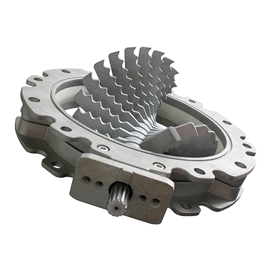
12.19 3.0 TECHNICAL FEATURES VAL.LBC.--.M.A2.1219.EN Issue: A2 3.1 Description of the device The LBC Lump Breaking Feeder Valve consists of a rotary shaft hold in position by two half-bodies. Built on the shaft, it rotates a series of blades angularly offset to each other, allowing them to compress the material lumps against the fixed grid, fastened to the lower half-bodies. -
Page 15: Operating Principle
12.19 3.0 TECHNICAL FEATURES VAL.LBC.--.M.A2.1219.EN Issue: A2 3.3 Operating principle The rotation of the blades compresses any lumps present in the material against the fixed grid causing them to get disintegrated. This operation preserves the machines downstream the Lump Breaking Feeder Valve from being fed material lumps that can clog it or lower its efficiency. - Page 16 12.19 3.0 TECHNICAL FEATURES VAL.LBC.--.M.A2.1219.EN Issue: A2 Materials that can be handled The device should only be used in accordance with current safety regulations. Do not make any modification or conversions. Additional add on parts require manufacturer approval. The device has been designed and manufactured as breaker of dry lumps that can be broken manually with no need of equipment max Mohs hardness 2= lumps can be scratched with fingemail.
-
Page 17: Improper Use Not Permitted
12.19 3.0 TECHNICAL FEATURES VAL.LBC.--.M.A2.1219.EN Issue: A2 3.5 Improper use not permitted It is forbidden working without safeguards in the form of mechanical or electrical safety devices where quick release fixing and or quick release openings are used. It is forbidden working without mechanical or electrical and/or electromechanical safety device(s) if the pre- scribed safety clearances are not to be complied with. -
Page 18: Noise Level
12.19 3.0 TECHNICAL FEATURES VAL.LBC.--.M.A2.1219.EN Issue: A2 3.6 Noise level Important The noise level depends on several factors such as dimensions, the nature of the material to be con- veyed and the filling rate. In accordance with the legal provisions in force, the client must carry out on-site measurement of the noise level, after assembly and however before commissioning the device, during operation of the de- vice in the worst conditions, to ensure that the level of noise reverberation doesn't put into any danger the operator during the operation of the device. -
Page 19: Safety And Information Signs
12.19 3.0 TECHNICAL FEATURES VAL.LBC.--.M.A2.1219.EN Issue: A2 3.9 Safety and information signs Danger - Warning Follow the signs on the plates. Ensure the plates are legible; otherwise clean them and replace the damaged ones, applying them in their original position. senso di rotazione direction of rotation NB: See the page 2, 1.2 Symbols... -
Page 20: Safety Devices
12.19 3.0 TECHNICAL FEATURES VAL.LBC.--.M.A2.1219.EN Issue: A2 3.10 Safety devices The access to the inner parts of the Lump Breaking Feeder Valve is not possible during operation. Unscheduled access is envisaged to remove foreign bodies and material deposits inside the device for ex- traordinary maintenance. -
Page 21: Information Regarding Handling And Transport
12.19 4.0 INFORMATION REGARDING HANDLING AND TRANSPORT VAL.LBC.--.M.A2.1219.EN Issue: A2 4.1 Type of packaging The type of packaging is selected according to the type of supply, the transport means used, the quantity of goods shipped and the destination. To facilitate shipment, the Lump Breaking Feeder Valve can be divided into several packages suitably pro- tected. -
Page 22: Reception Of Goods
12.19 4.0 INFORMATION REGARDING HANDLING AND TRANSPORT VAL.LBC.--.M.A2.1219.EN Issue: A2 4.2 Reception of goods On receiving the goods, ensure that the type and quantity correspond to the data present on the acknowledge- ment of order. Possible damage has to be immediately communicated in writing in the space provided to this purpose in the waybill. - Page 23 12.19 4.0 INFORMATION REGARDING HANDLING AND TRANSPORT VAL.LBC.--.M.A2.1219.EN Issue: A2 Caution DO NOT PUSH OR DRAG THE SECTIONS OF THE DEVICE. All operations have to be carried out by qualified and authorized personnel. The personnel authorized to handle the device have to possess the right skills and experience to put into effect all measures necessary to ensure his safety and the safety of the persons involved.
-
Page 24: Installation And Fixing
12.19 5.0 INSTALLATION AND FIXING VAL.LBC.--.M.A2.1219.EN Issue: A2 5.1 Safety prescriptions for installation Important Currently and valid regulation regarding safety clearances must be complied with. If the prescribed safety clearances are not to be complied with the hazard points must be mechanical- ly, electrically and/or electro-mechanically secured. -
Page 25: Preparing The Assembly Place (In Charge Of The Client)
12.19 5.0 INSTALLATION AND FIXING VAL.LBC.--.M.A2.1219.EN Issue: A2 5.2 Preparing the installation place (in charge of the client) Danger - Warning RISK OF INJURY! Body parts could be severed by rotating components if the product infeed and/or discharge are open. FIT SAFEGUARDS TO PREVENT ANYONE REACHING INTO THE PRODUCT INFEED AND/OR DIS- CHARGE. -
Page 26: Supply
12.19 5.0 INSTALLATION AND FIXING VAL.LBC.--.M.A2.1219.EN Issue: A2 5.3 Supply All Lump Breaking Feeder Valves have been pre-assembled at the factory. Actuator is supplied separately. 5.4 Assembling and fastening the device Remove the packaging. Fit the actuator (drive unit, hydraulic or other). 1. - Page 27 12.19 5.0 INSTALLATION AND FIXING VAL.LBC.--.M.A2.1219.EN Issue: A2 11. Ensure the LBC direction of rotation is correct according indications reported. 12. The LBC must be installed beneath hoppers sufficiently deep so as to prevent reaching of the moving parts with the limbs. 13.
- Page 28 12.19 5.0 INSTALLATION AND FIXING VAL.LBC.--.M.A2.1219.EN Issue: A2 SPECIAL INSTALLATION WITH DUMPING DEVICE Danger - Warning RISK OF INJURY! The currently valid regulations regarding safety clearances must be complied with. IF THE PRESCRIBED SAFETY CLEARANCES ARE NOT TO BE COMPLIED WITH THE HAZARD POINTS MUST BE MECHANICALLY, ELECTRICALLY AND/OR ELECTRO- MECHANICALLY SECURED.
-
Page 29: Assembling Instructions
12.19 5.0 INSTALLATION AND FIXING VAL.LBC.--.M.A2.1219.EN Issue: A2 5.5 Assembling instructions Assembling the electro-mechanical actuator - AE Type The supply includes: A) 1 electrical actuator; B) 2 hex bolts. In order to readily assemble the mechanical actuator, remove only the walls of the package and leave the Lump Breaking Feeder Valve secured to the pallet and related base supports. -
Page 30: Assembling-Disassembling Phases
12.19 5.0 INSTALLATION AND FIXING VAL.LBC.--.M.A2.1219.EN Issue: A2 5.6 Assembling-disassembling phases Unscrew the screws of the crate cover. Remove the screws that secure the LBC to the packaging. Carefully remove the LBC from the packaging paying attention to leave the grid inside the pack- aging. - Page 31 12.19 5.0 INSTALLATION AND FIXING VAL.LBC.--.M.A2.1219.EN Issue: A2 Position the LBC on two supports so as the blades do not touch the floor and remove the fastening bolts of the holders. Rotate the device upside down. Unscrew the other 2 fastening screws of the the actuator bracket.
- Page 32 12.19 5.0 INSTALLATION AND FIXING VAL.LBC.--.M.A2.1219.EN Issue: A2 Unscrew the remaining screws by collecting the nut from the bottom. Lift the upper half -body and slide the actuator bracket attachment out. Remove the upper half-body.
- Page 33 12.19 5.0 INSTALLATION AND FIXING VAL.LBC.--.M.A2.1219.EN Issue: A2 Lift the shaft and remove the anti-friction bushing from the splined side. Remove the anti-friction bushing from the oppo- site splined side. Remove the shaft from the lower half-body.
- Page 34 12.19 5.0 INSTALLATION AND FIXING VAL.LBC.--.M.A2.1219.EN Issue: A2 Remove the seal from the side which is not splined and proceed on the other side. Remove the seal paying attention not to damage with the blades or the tools. Remove the Seeger ring from the blocker on the driven shaft side.
- Page 35 12.19 5.0 INSTALLATION AND FIXING VAL.LBC.--.M.A2.1219.EN Issue: A2 Remove the retaining ring. Remove the blades and spacers. After the blades have been extracted, remove the Seeger ring and the bushing from the splined side.
- Page 36 12.19 5.0 INSTALLATION AND FIXING VAL.LBC.--.M.A2.1219.EN Issue: A2 Insert the bushing on the shaft from the splined side. Fit the Seeger ring in its slot and make sure it is fully inserted. Mark with a marker one of the six sides of the hexagon as a reference for the blades alignment.
- Page 37 12.19 5.0 INSTALLATION AND FIXING VAL.LBC.--.M.A2.1219.EN Issue: A2 Insert the blade number 1 on the shaft by placing the alignment mark of the blade at mark made on the shaft. Insert a spacer on the shaft. Insert the blade number 2 on the shaft by placing the alignment mark of the blade at mark made on the shaft.
- Page 38 12.19 5.0 INSTALLATION AND FIXING VAL.LBC.--.M.A2.1219.EN Issue: A2 After all blades are fitted, insert the bushing. Lock the retaining ring by fitting the Seeger ring in the slot and make sure it is fully inserted in its seat. Clean thoroughly the seal and check to make sure it is not damaged.
- Page 39 12.19 5.0 INSTALLATION AND FIXING VAL.LBC.--.M.A2.1219.EN Issue: A2 Insert the seal also in the opposite shaft end. Be careful not to cut the gasket with the blades. Check to make sure the friction bushing is not damaged and/or worn. Insert it on the shaft from the splined side. Check to make sure the friction bushing is not damaged and/or worn.
- Page 40 12.19 5.0 INSTALLATION AND FIXING VAL.LBC.--.M.A2.1219.EN Issue: A2 Lay the shaft so assembled on one of the half- bodies causing the bushes to enter their seats. Push the seal inside its seat along the whole cir- cumference. After you have entered all screws in the second half-body, pair it with the rest of the LBC.
- Page 41 12.19 5.0 INSTALLATION AND FIXING VAL.LBC.--.M.A2.1219.EN Issue: A2 Insert the actuator fastening bracket by matching the centring cylinders. Tighten the actuator fastening bracket screws by applying 30Nm torque. Position the nuts inside the hexagonal seats placed in lower half-body and support it with a fin- ger while the screw is being tighten.
-
Page 42: Electrical Connections
The type of motor connection depends on the voltage value available to be applied; please, refer to the wiring diagram provided for each motor. The illustration shows the wiring diagrams of the motor supplied by WAM . Consult the manual available on ®... -
Page 43: Earthing
12.19 5.0 INSTALLATION AND FIXING VAL.LBC.--.M.A2.1219.EN Issue: A2 The installer has to provide to interfacing the equipment with the necessary controls: start/stop, emergency stop, reset after an emergency stop, in compliance with the regulatory standards in force (CEI EN 60204-1, UNI EN 1037, UNI EN 1088, CEI EN 50014). -
Page 44: Emissions Into The Atmosphere
12.19 5.0 INSTALLATION AND FIXING VAL.LBC.--.M.A2.1219.EN Issue: A2 5.10 Emissions into the atmosphere The device does not releases emissions into the atmosphere. 5.11 Lighting The device has to be placed in a properly lightened area. Danger - Warning In case of maintenance operations carried out in scarcely lightened areas, use additional lamps that ensure the proper safety conditions according to the legal provisions in force. -
Page 45: Limits Of Use, Technical Data And Operating Conditions
12.19 5.0 INSTALLATION AND FIXING VAL.LBC.--.M.A2.1219.EN Issue: A2 Start the device on empty to ensure the direction of rotation of the blades is correct. Operate the Lump Breaking Feeder Valve for about 1/3 minutes to ensure it works properly. In case of: - unusual noise;... -
Page 46: Information Regarding Use
12.19 6.0 INFORMATION REGARDING USE VAL.LBC.--.M.A2.1219.EN Issue: A2 6.1 Production Start-up Before starting up the Lump Breaking Feeder Valve, the operator in charge and authorized for the produc- tion must ensure the safety devices installed are working and the operating conditions are matched (hatches closed, inlet and outlet spouts connected correctly o protected, etc.). -
Page 47: Shutting Down The Device
12.19 6.0 INFORMATION REGARDING USE VAL.LBC.--.M.A2.1219.EN Issue: A2 A link with different load points requires the device to be dimensioned largely enough to carry the sum of all courses. This is particularly important when the transported material tends to harden or get compacted if not handled for a certain period of time. -
Page 48: Operation Conditions
12.19 6.0 INFORMATION REGARDING USE VAL.LBC.--.M.A2.1219.EN Issue: A2 6.4 Operation conditions OPERATION ENVIRONMENT Important The device must not be employed in environments and areas: - that contains highly corrosive and/or abrasive vapours, gas or dust; - in presence of fire and/or heat above the permitted temperatures; - if there is a fire or explosion hazard and it is required the usage of sparktrap or explosion-proof components. -
Page 49: Clearing The Lump Breaking Feeder Valve After Clogging
12.19 6.0 INFORMATION REGARDING USE VAL.LBC.--.M.A2.1219.EN Issue: A2 6.5 Clearing the Lump Breaking Feeder Valve after clogging If, during normal operation, the Lump Breaking Feeder Valve actuator is found to be moving gradually under force and then comes to a complete stop, it is highly probable that the problem is caused by a blockage. Danger - Warning The operator assigned must apply rigorously all adjustments regarding safety at the workplace and take the appropriate measures against industrial accidents. -
Page 50: Long Shut-Downs Of The Device
12.19 6.0 INFORMATION REGARDING USE VAL.LBC.--.M.A2.1219.EN Issue: A2 6.7 Long shut-downs of the device When the Lump Breaking Feeder Valve has to remain unused for long periods, proceed as described below. In case the device and/or its components are to be stored and preserved for a certain period of time, in a closed and dry material at room temperature of (5 -40°C) before re-commissioning them, in order to avoid damages or deterioration check that the electrical mechanisms and the structure are not damaged;... -
Page 51: Information Regarding Maintenance
12.19 7.0 INFORMATION REGARDING MAINTENANCE VAL.LBC.--.M.A2.1219.EN Issue: A2 Danger - Warning Before carrying out any maintenance activity, activate all the safety devices to ensure the safety of the persons involved in the operations and those nearby. Set the equipment concerned in safety condition. Wear suitable personal protection equipment;... -
Page 52: Maintenance Activity Register
12.19 7.0 INFORMATION REGARDING MAINTENANCE VAL.LBC.--.M.A2.1219.EN Issue: A2 Every two months, check the wear condition of the blades. NOTE: The previous indications are to be taken roughly; the wear is directly proportional to the nature of the material handled and the hours of operation. Danger - Warning PRIOR TO ANY OPERATION, DISCONNECT THE EQUIPMENT FROM THE MAINS! Danger - Warning... -
Page 53: Cleaning
12.19 7.0 INFORMATION REGARDING MAINTENANCE VAL.LBC.--.M.A2.1219.EN Issue: A2 7.2 Cleaning Only trained and instructed personnel are permitted to carry out the cleaning work. Machine Hygiene level 1 (EN ISO 14159); LBC is suitable for use with no critical dry, stable and not easily perishable foodstuffs Clean the outside part of the equipment (the device) using a vacuum cleaner to prevent dispersal of dust in the environment and in the surrounding area;... -
Page 54: Lubrication
12.19 7.0 INFORMATION REGARDING MAINTENANCE VAL.LBC.--.M.A2.1219.EN Issue: A2 7.3 Lubrication Lubrication operations must be performed (see the periodic checks table) using conductive lubricant pastes on the following cleaned parts: - splined shaft; - grounding contact bolt. Danger - Warning POSSIBILITY OF CONTACT WITH LUBRICANT/PRODUCT! During machine production and product processing, products may occasionally have technically una- voidable contact with lubricant, even unintentionally. -
Page 55: Replacement Of Parts
12.19 8.0 REPLACEMENT OF PARTS VAL.LBC.--.M.A2.1219.EN Issue: A2 8.1 Safety recommendations for replacement Danger - Warning The replacement operations must be carried out by a specialist authorized technician with specific skills in the sector concerned (mechanical, electrical etc). Before carrying out any operation, provide suitable safety measures and use the appropriate equip- ment to prevent risk of work injuries to persons involved in the operations and those nearby. -
Page 56: Replacing The Wear Parts
12.19 8.0 REPLACEMENT OF PARTS VAL.LBC.--.M.A2.1219.EN Issue: A2 8.2 Replacing the wear parts The Lump Breaking Feeder Valve wear parts are: - seal; - bushings; - rotary blades; - fixed grid. These components must be replaced after a certain period depending on the type of material being handled and the conditions of use of the Lump Breaking Feeder Valve. -
Page 57: Decommissioning
12.19 8.0 REPLACEMENT OF PARTS VAL.LBC.--.M.A2.1219.EN Issue: A2 8.3 Decommissioning In case it is not possible to restore the proper functioning of the device after failure, proceed to its decommis- sioning and warn on its failure by means of a special a warning sign, then require the assistance by contacting the WAMGROUP S.p.A. -
Page 58: Information Regarding Faults
12.19 9.0 INFORMATION REGARDING FAULTS VAL.LBC.--.M.A2.1219.EN Issue: A2 9.1 Trouble-shooting Minor problems can be solved without consulting a specialist. The following Table contains a list of the most common problems, the possible causes and possible remedies. For particularly difficult actions which are not mentioned in the Table, contact the Manufacturer’s Customer Service Department. -
Page 59: Check-List In Case Of Fault
12.19 9.0 INFORMATION REGARDING FAULTS VAL.LBC.--.M.A2.1219.EN Issue: A2 9.2 Check-list in case of fault If you have been unable to solve the problem on the device even after having carried out the operations sug- gested in paragraph “Trouble-shooting” please contact the plant technician/installer/or the Manufacturer. If technical assistance is required, in addition to the device data, the plant technician/installer or Manufacturer will also need information concerning the plant in which the device is installed, its installation and its working, for better identification of the problem that has occurred. -
Page 60: Technical Data
12.19 10.0 TECHNICAL DATA VAL.LBC.--.M.A2.1219.EN Issue: A2 Overall dimensions of the device SIZE MODEL LBC0150 DIN5482 146.5 2 x M10 2 x M12 13.3 LBC0200 DIN5482 2 x M10 2 x M12 13.7 17.5 LBC0250 DIN5482 2 x M10 2 x M12 17.9 21.3 LBC0300... -
Page 61: Wear Parts And Spare Parts
12.19 11.0 WEAR PARTS AND SPARE PARTS VAL.LBC.--.M.A2.1219.EN Issue: A2 Check the drawing and table below to identify the components of the Lump Breaking Feeder Valve. A) Half-bodies B) Rotary blades C) Seal D) Bushings E) Actuator fixing bracket F) Grid G) Hexagonal shaft... -
Page 62: Aattachments
12.19 A ATTACHMENTS VAL.LBC.--.M.A2.1219.EN Issue: A2 A1 Nuts and bolts tightening torque Table Tightening Torque [Nm] Thread Diameter Resistance Class 8.8 Resistance Class 10.9 Resistance Class 12.9 13.0 16.0 23.0 32.0 39.0 46.0 64.0 77.0 80.0 110.0 135.0 125.0 180.0 215.0 195.0 275.0...
Need help?
Do you have a question about the LBC Series and is the answer not in the manual?
Questions and answers