Table of Contents
Advertisement
Quick Links
BEFORE USING THE POWER SUPPLY UNIT
Be sure to read this instruction manual thoroughly before using this product. Pay attention to all cautions and warnings before using this product.
Incorrect usage could lead to an electrical shock, damage to the unit or a fire hazard.
DANGER
Never use this product in locations where flammable gas or ignitable substances are present. There are risks of igniting these substances and
exploding by an arcing.
WARNING
Do not touch this product or its internal components while circuit is live, or shortly after shut down. There may be high voltage or high
temperature present and you may receive an electric shock or burn.
When this product is operating, keep your hands and face away from it as you may be injured by an unexpected situation.
Do not make unauthorized changes to this product, otherwise you may receive an electric shock and void your warranty.
Do not drop or insert anything into this product. It might cause a failure, fire and electric shock.
Do not use this product under unusual condition such as emission of smoke or abnormal smell and sound etc. It might lead to fire and electric
shock. In such cases, please contact us. Do not attempt repair by yourself, as it is dangerous for the user.
Do not operate these products in the presence of condensation. It might lead fire or electric shock.
CAUTION
This power supply is designed and manufactured for use within an end product such that it is accessible to SERVICE ENGINEERS only.
Confirm connections to input/output terminals are correct as indicated in the instruction manual before switching on.
Input voltage, Output current, Output power, ambient temperature and ambient humidity should be kept within specifications, otherwise the
product will be damaged.
Do not use this product in environment with a strong electromagnetic field, corrosive gas or conductive substances.
For applications, which require very high reliability, it is necessary to provide a fail-safe mechanism in the end equipment.
Do not inject abnormal voltages into the output of this product. The injection of reverse voltage or over voltage exceeding nominal output
voltage into the output terminal might cause damage to internal components.
Never operate the product under over current or short-circuit conditions for more than 30 seconds, or outside its specified Input Voltage Range.
Insulation failure, smoking, burning or other damage may occur.
This product contains a printed circuit board utilizing surface mounted devices. PCB stress such as bending, twisting etc. could cause damage.
Therefore, please handle with care.
When handling this product, hold the board edge and take care not to touch the component side. If the application environment with strong
vibration,please mount it on spacers,when installing this product in apparatus or equipment .
The outputs of this product may, under fault conditions, exceed SELV voltage limits. Therefore the outputs must be earthed in the end
equipment to maintain SELV. If the outputs are not earthed, they must be considered hazardous and must not be made user accessible.
This product has used Power Thermistor to protect the circuit from Inrush Current. Frequent repetition of input on/off might cause damage to
internal components because of generating surge current.
Breaking of internal fuse is considered internal failure. In such cases, please contact us.
The information in this document is subject to change without prior notice. Please refer to the latest version of the data sheet, etc., for the most
up-to date specifications of the product.
No part of this document may be copied or reproduced in any form without prior written consent of TDK-Lambda.
CUT75
Instruction Manual
TDK-Lambda
CUT75
Instruction Manual
CA809-04-01B
Advertisement
Table of Contents

Related Manuals for TDK-Lambda CUT75


Summary of Contents for TDK-Lambda CUT75
- Page 1 The information in this document is subject to change without prior notice. Please refer to the latest version of the data sheet, etc., for the most up-to date specifications of the product. No part of this document may be copied or reproduced in any form without prior written consent of TDK-Lambda. CA809-04-01B...
-
Page 2: Important Safety Instructions
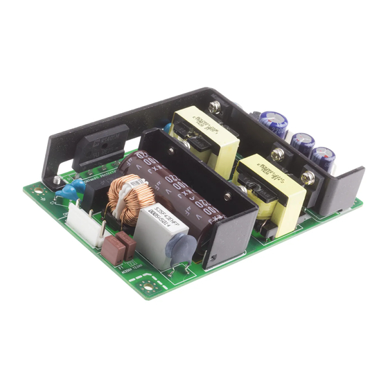
Servicing These products are not customer serviceable. Repairs may only be carried out by TDK-Lambda.or their authorized agents. These products are not authorized for use as critical components in nuclear control systems, life support systems or equipment for use in hazardous environments without the express written approval of the Managing Director of TDK-Lambda Corporation. - Page 3 TDK-Lambda CUT75 Instruction Manual 1.Model name identification method CUT 75 – 522 / □ Option (*1) *1 Blank : Standard type /A : With U type chassis and cover model Rated Output Voltage /L : With U type chassis /B : With base plate model...
- Page 4 TDK-Lambda CUT75 Instruction Manual 3.Block Diagram 4.Sequence time chart - 3 -...
-
Page 5: Input/Output Connector
TDK-Lambda CUT75 Instruction Manual 5. Terminal Connection Method Pay attention to the input wiring. If it is connected to wrong terminal, the power supply will be damaged. Input must be off when making connections. Connect terminal of input connector and mounting hole to protective earth of the equipment. -
Page 6: Inrush Current
TDK-Lambda CUT75 Instruction Manual 6-1-1. Input Voltage vs Output Derating Output derating is required when the power supply operate below 100VAC input. Refer to table below for details. A,B,C,D,E,F Input voltage(VAC) LOADING CONDITION(%) Input voltage All Mounting (A,B,C,D,E,F) 85VAC 100VAC-265VAC 6-2. -
Page 7: Output Ripple & Noise
TDK-Lambda CUT75 Instruction Manual 6-6. Output Ripple & Noise The standard specification for maximum ripple value is measured according to measurement circuit specified by JEITA-RC9131A. When load lines are longer, ripple will becomes larger. In this case, electrolytic capacitor, film capacitor, etc. might be necessary to use across the load terminal. -
Page 8: Mounting Directions
2. If there is external noise filter and Y-caps connected at the input and output of the power supply, the voltage distribution between primary and secondary circuit will be changed during the withstand voltage test, and may cause test fail. In this case, please contact TDK-Lambda for the technical support and instructions. - Page 9 TDK-Lambda CUT75 Instruction Manual 7-2. Output Derating Make sure that the specified temperature range is maintained. ▥ CONVECTION COOLING (STANDARD MODEL AND /B MODEL) A,C,D,E LOADING CONDITION(%) Ta (°C) Mounting Mounting Mounting A,C,D,E -20~40 T a (°C) ▥ CONVECTION COOLING (/L AND /A MODEL) LOADING CONDITION(%) Ta (°C)
-
Page 10: Mounting Method
▥ Mounting Holes size Height more than 8mm spacer CUT75: 4 HOLES 3.5mm Allowable area by metal pieces is 8mm from each PCB corners. Refer to figure below. CUT75 ▥ Condition to meet Isolation & Withstand Voltage standard. - Page 11 Have to use slow-blow or time-lag type fuse, not fast-blow fuse. Fuse rating is considered by in-rush current value at line turn-on. Do not select the fuse according to input current (RMS.) values under the actual load condition CUT75: 2.5A 11. Before concluding that the unit is at fault (1) Check if the rated input voltage is connected.
Need help?
Do you have a question about the CUT75 and is the answer not in the manual?
Questions and answers