Table of Contents
Advertisement
Advertisement
Table of Contents

Summary of Contents for RC Systems SenSmart 5000
- Page 1 Remote Sensor SenSmart 5000 Installation Guide Flammable & Toxic Gas Detectors Smart Alarm Controllers Fire & Gas System Engineering Technical Service & Support Warning: Read & understand contents of this manual prior to operation. Failure to do so could result in serious injury or death.
-
Page 2: Getting Started
Gas Detector Installation and Power-up What you need (not included) Small Flathead Screwdriver Phillips Screwdriver (for poly enclosure) Wire (RC Systems recommends: Belden 3124A Multi-Conductor wire or equivalent.) Installation of Gas Detector Remove windowed lid from unit. AL Enclosure -... - Page 3 Connect 10-30VDC power lead to TB2.1 (See Figure 1) Connect Common lead to TB2.3 (See Figure 1) Connect signal lead to TB2.5. (4-20mA Out) (if required)(See Figure 1) Figure 1 - SenSmart 5000 wiring Remote Sensor...
-
Page 4: Remote Sensor Installation
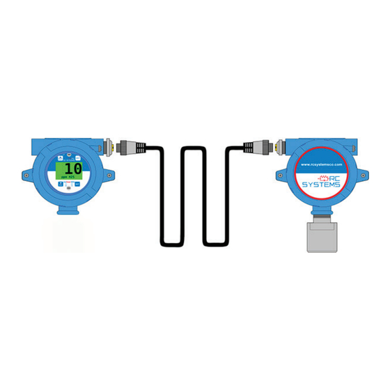
REMOTE SENSOR INSTALLATION SenSmart 5000 Wiring Instructions Follow the steps below to first connect the SenSmart 5000 I/O Board to the Remote Sensor: Verify SenSmart 5000 is powered off. Remove lid from SenSmart 5000 and remote sensor Connect (24V) TB.1.1on the Remote sensor board to the10-30VDC power supply on SenSmart 5000 I/O board (TB2.1). - Page 5 Option board to the Remote Sensor: Locate the 10-0532 relay/Modbus board or 10-0531 Modbus board. (This board is “piggybacked” behind the 10-0387 SenSmart 5000 CPU/Display Board.” Connect Modbus Terminal A (TB1.3) from the remote sensor board to terminal A on Modbus Board (TB1.1).
- Page 6 Figure 2 - Remote Sensor Power Up www.rcsystemsco.com...
-
Page 7: Configuration Instructions
Entering Configuration Mode: Transmitter (SenSmart 5000): 1. Swipe Edit on the transmitter using a magnet. 2. Swipe Down until Comm Settings is highlighted. 3. Swipe Edit to enter the Comm Settings menu. - Page 8 Figure 3- Configuration...
-
Page 9: Complete Setup
COMPLETE SETUP Finalize Installation Replace display and tighten screws. Replace enclsoure lid. Apply power to unit and observe power up screen. After the warm up period, observe gas type and gas concentration on screen. Using the magnet wand, swipe Down Key on the display. Follow on-screen prompts to perform calibration. - Page 10 R.C. Systems provides 24/7 superior technical support from experts right here in our local facility. If you are in need of any assistance during the setup of this product, you may contact our main office and your call will be directed appropriately. At R.C.


Need help?
Do you have a question about the SenSmart 5000 and is the answer not in the manual?
Questions and answers