Table of Contents
Advertisement
Quick Links
4/10/2019
V4 User Manual and Installation
Guide
Updated · January 23, 2019
Introduction
System Overview
Installation Checklist
V4 Equipment
General Guidelines
V4 Mounting
V4 Pin Configuration
Power And Data Connections
4 Pin Testing and Cable Management
Wiring Guidelines
External GPS Antenna (Optional)
GPS System Check
System Checklist
System Specifications
V4 and Mount Dimensions
Typical Installation
System Installation
Zonar Discrete Input System
Notices
Warranty And Legal Notices
https://support.zonarsystems.net/hc/en-us/articles/360017847851-V4-User-Manual-and-Installation-Guide
V4 User Manual and Installation Guide – Zonar Systems Support
1/27
Advertisement
Table of Contents

Subscribe to Our Youtube Channel
Related Manuals for Zonar V4

Summary of Contents for Zonar V4
- Page 1 4/10/2019 V4 User Manual and Installation Guide – Zonar Systems Support V4 User Manual and Installation Guide Updated · January 23, 2019 Introduction System Overview Installation Checklist V4 Equipment General Guidelines V4 Mounting V4 Pin Configuration Power And Data Connections...
-
Page 2: System Overview
Refer to your specific vehicle manufacturer guidelines for the installation of electrical components and wiring. Details on operating the V4 and its built-in applications and so ware are given in this guide. A professional team of Zonar support technicians and engineers are available to answer your installation questions. -
Page 3: Installation Checklist
4/10/2019 V4 User Manual and Installation Guide – Zonar Systems Support Installation Checklist Task Task Required? Complete? Inventory all V4 components and accessories Required Lay out all cables and accessories in accordance with: Required - General guidelines Required ... - Page 4 Disconnect vehicle battery ground cable Suggested Install V4 Power/Data cable. Do not connect 4-pin connector to V4 at this time. Do not Required connect OBDII connector to vehicle at this time (if used). 10 Install Discrete IO cable If used ...
-
Page 5: General Guidelines
3. Verify placement acceptability with State DOT/Law enforcement prior to installation. 4. V4 has a temperature range of -40°C (-40°F) to +85°C (+185°F). Do not mount V4 in hot engine compartments or near hot exhaust components. -
Page 6: Drill Holes
(included) for optimal system protection. 4. Electrical fuses should be installed as close as possible to the source of power. 5. Do not connect to the 4 pin power input until all other V4 cables have been connected. Drill Holes 1. Do not drill into the V4 unit. This will void the warranty. -
Page 7: General Housekeeping
To comply with FCC RF exposure requirements for mobile transmitting devices, this device must be installed to provide a separation distance of at least 25 cm (10 inches) from all persons. See General Guidelines. The installation technician must record which V4 unit is being installed in each vehicle. https://support.zonarsystems.net/hc/en-us/articles/360017847851-V4-User-Manual-and-Installation-Guide... -
Page 8: Mounting Areas
1. Find the GPS ID # on the back of the unit labeled “GPSID (S/N) 18xxxxxx.” 2. Record the asset (vehicle name) and the GPS being installed—this is important information for Zonar Customer Care or the Ground Tra ic Control Administrator. - Page 9 4/10/2019 V4 User Manual and Installation Guide – Zonar Systems Support 2. Zonar logo towards sky V4 Pin Configuration 1. External GPS antenna (Optional) 2. 4 Pin Power Input (Disconnect first, Reconnect last) 3. 6 Pin Accessory Port: Z Pass™/Operator ID 4.
-
Page 10: Power And Data Connections
Additionally there is a fi h uncommon cable specifically used to wire around battery disconnect systems: 5. 4 Pin, 4 Wire Power Cable (part# 10030) See General Guidelines before you begin. Do not connect to the 4 pin power input until all other V4 cables have been connected. - Page 11 4/10/2019 V4 User Manual and Installation Guide – Zonar Systems Support Use on light duty vehicles equipped with OBDII Diagnostic Port™. Requirements: OBDII_sticker.png 1. OBDII Diagnostic Port 2. Sticker or plate under the hood explicitly stating "OBDII Compliant" or "OBDII Certified". See example to right.
- Page 12 Note: This cable requires specific adapters dependent on vehicle make/model/year and engine manufacturer. The necessary adapters should be provided with the initial installation kit, but if assistance is needed, contact Zonar Customer Support for additional information.
- Page 13 1. All power leads must be connected to the vehicles protected circuitry (for example, the fuse panel and circuit breaker panel protected circuits). Never electrically connect Zonar equipment to unprotected circuits (for example, directly to the battery). 2. All power leads (red and white) must be protected with a 3 to 5 amp fuse and inline fuse holder (included) for optimal system protection.
- Page 14 If power cabling is not connected and powered as described in the Power Bundle Wiring section, one or more of the following conditions may occur. Contact Zonar Customer Support for additional information. Cold Start flags (an indicator that a unit lost and regained constant power)
-
Page 15: Wiring Guidelines
The wiring guidelines in this section are for unterminated power and ground leads—4 Pin and Backbone. The authorized method for power termination on the Zonar V4 system is the use of Add-a-Circuit fuse taps. Whenever possible, use fuse taps for power termination. If fuse taps cannot be used due to the particular make/model/year of the vehicle being installed, then the poke and weave method of termination can be utilized. - Page 16 V4 User Manual and Installation Guide – Zonar Systems Support CAUTION: Zonar has approved two types of fuse taps. Use of other brands is not authorized. Do not install these fuse kits in fuse panel locations greater than 10 amps.
-
Page 17: External Gps Antenna (Optional)
External GPS Antenna (Optional) External antennas are generally only necessary if the V4 GPS unit is enclosed in a radio signal interfering area (e.g. metallic box, under seats, on dashboards with flat windshields, and in cabs or cockpits constructed primarily from metallic material). -
Page 18: Gps System Check
Zonar’s Ground Tra ic Control® website should be performed. Not all installers will have access to this area; check with a Zonar Customer Service representative if in doubt. This procedure covers the minimum requirements for a system installer. -
Page 19: System Checklist
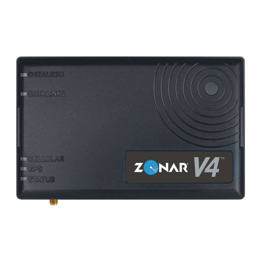
4/10/2019 V4 User Manual and Installation Guide – Zonar Systems Support Single blink per second if no ECM connection or if ECM connection not working properly. DATALINK Single green blink per second if J1939 data is present. Single green blink per second if good communication between the Light Duty cable and the GPS device. -
Page 20: System Specifications
4/10/2019 V4 User Manual and Installation Guide – Zonar Systems Support System Specifications Electrical DC Input Range: 8 VDC to 32 VDC Operating Current: 100 mA @12V (typical without peripherals) 500 mA @12V (maximum without peripherals) https://support.zonarsystems.net/hc/en-us/articles/360017847851-V4-User-Manual-and-Installation-Guide 20/27... - Page 21 4/10/2019 V4 User Manual and Installation Guide – Zonar Systems Support Key-O Current: <1mA Environmental Operating Temp: -40C to 85C Storage Temp: -40C to 85C Humidity: 95% R.H., non-condensing Shock/Vibration: SAE J1455, MIL-STD-202G GNSS Receiver GPS/Glonass WAAS, EGNOS, MSAS, GAGAN, QZSS...
-
Page 22: Typical Installation
4/10/2019 V4 User Manual and Installation Guide – Zonar Systems Support DIMENSIONS IN INCHES Note that these are reference dimensions only. Typical Installation https://support.zonarsystems.net/hc/en-us/articles/360017847851-V4-User-Manual-and-Installation-Guide 22/27... - Page 23 4/10/2019 V4 User Manual and Installation Guide – Zonar Systems Support External Antenna Installation (Optional) https://support.zonarsystems.net/hc/en-us/articles/360017847851-V4-User-Manual-and-Installation-Guide 23/27...
-
Page 24: System Installation
4/10/2019 V4 User Manual and Installation Guide – Zonar Systems Support System Installation https://support.zonarsystems.net/hc/en-us/articles/360017847851-V4-User-Manual-and-Installation-Guide 24/27... - Page 25 V4 User Manual and Installation Guide – Zonar Systems Support Zonar Discrete Input System The V4 is capable of recording GPS points when a system on the vehicle is activated or deactivated. See below schematic to tap into an existing switched control circuit.
- Page 26 20 AWG wire gauge Notices Warning: (Part 15.21) Changes or modifications not expressly approved by Zonar Systems could void the user's authority to operate the equipment. Caution: RF Exposure (OET Bulletin 65) To comply with FCC RF exposure requirements for mobile transmitting devices, the antenna(s) used for this transmitter must be installed to provide a separation distance of at least 25 cm (10 inches) from all persons and must not be co- https://support.zonarsystems.net/hc/en-us/articles/360017847851-V4-User-Manual-and-Installation-Guide...
- Page 27 4/10/2019 V4 User Manual and Installation Guide – Zonar Systems Support located or operating in conjunction with any other antenna or transmitter. Users and installers must be provided with antenna installation instructions and transmitter operating conditions for satisfying RF exposure compliance.
Need help?
Do you have a question about the V4 and is the answer not in the manual?
Questions and answers