Table of Contents
Advertisement
Advertisement
Table of Contents

Subscribe to Our Youtube Channel
Related Manuals for Zonar V4

Summary of Contents for Zonar V4
- Page 1 Installation/User Guide ™ REV: 04/06/18...
-
Page 2: Table Of Contents
Drill Holes ..........................10 Cable Management ........................10 Cable Management Examples ..................... 10 General Housekeeping ......................11 V4 Mounting Plate and Unit ......................11 Mounting Areas ........................12 Mounting Considerations ......................12 Orientation and Placement ..................... 13 V4 Pin Configuration ........................14 Power/Data Cables ........................ - Page 3 Check the LEDs ......................... 24 Turn Key Off ..........................25 Turn to Accessory Position ...................... 25 System Checklist .......................... 26 System Specifications ........................27 Electrical ........................... 27 Environmental .......................... 27 GNSS Receiver .......................... 27 Cellular ............................27 V4™ Installation/User Guide...
- Page 4 External GPS Antenna (optional) ..................... 27 V4 and Mount Dimensions ......................28 Typical Installation ........................29 Installation Example ........................30 System Installation ........................31 Zonar Discrete Input System ....................... 32 Warranty ............................33 Notices ............................34 Legal Information ......................... 35 V4™...
-
Page 5: Introduction
Please refer to your specific vehicle manufacturer guidelines for the installation of electrical components and wiring. Details on operating the V4 and its built-in applications and software are given in this guide. A professional team of Zonar support technicians and engineers are available to answer your installation questions. -
Page 6: System Overview
System Overview V4™ Installation/User Guide... -
Page 7: Installation Checklist
If used Install external GPS antenna If used Install V4 mount plate & V4 Required Interconnect all cables & wires to V4 (except 4 pin power) Required Reconnect vehicle battery ground cable Suggested Connect 4 pin power cable to V4... -
Page 8: V4 Equipment
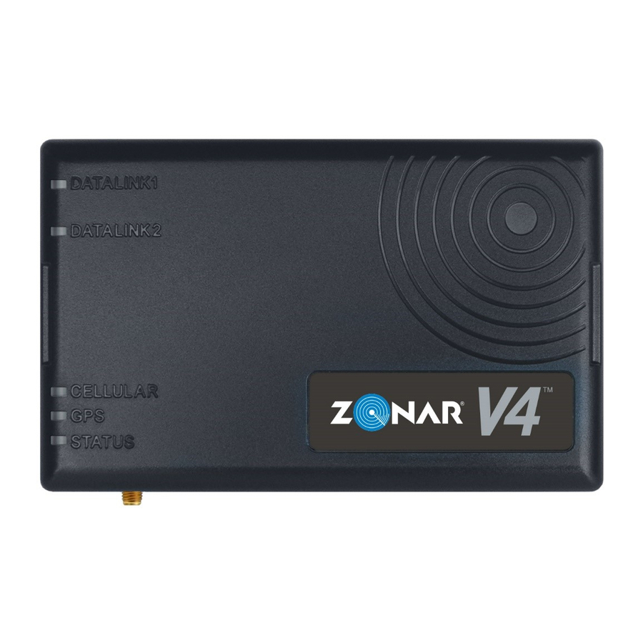
V4 Equipment A. V4 GPS Unit B. V4 Mounting Plate and Mounting Screws (Provided) C. GPS Antenna (Optional) D. GPS Antenna Adhesive Tag (Optional - used for non-magnetic rooftop GPS Antenna installs) Note: See External GPS for detailed information on GPS antenna requirements and recommendations. -
Page 9: General Guidelines
(included) for optimal system protection. • Electrical fuses should be installed as close as possible to the source of power. • Do not connect to the 4 pin power input until all other V4 cables have been connected. V4™... -
Page 10: Drill Holes
Drill Holes • Do not drill into the V4 unit. This will void the warranty. • Capture all drill chips during drilling operations. Do not allow chips to fall onto equipment, furnishings, etc. • Deburr all drill holes on both sides of drilled surface. The following is an example of a deburr tool: •... -
Page 11: General Housekeeping
General Guidelines. The installation technician must record which V4 unit is being installed in each vehicle. 1. Find the GPS ID # on the back of the unit labeled “GPSID (S/N) 18xxxxxx.” 2. Record the asset (vehicle name) and the GPS being installed—this is important information for Zonar Customer Care or the Ground Traffic Control Administrator. -
Page 12: Mounting Areas
• To prevent water damage, do not install below windows or doors that open to the vehicle’s exterior. Note: If enclosing in a radio-shielded area (for example, metallic enclosure) an external GPS antenna may be necessary for proper operation and performance. V4™ Installation/User Guide... -
Page 13: Orientation And Placement
Orientation and Placement V4™ Installation/User Guide... -
Page 14: V4 Pin Configuration
5. 12 Pin Discrete Input (Optional) 6. 10 Pin ECM input (SAE J1708/J1939 & OBDII equipped vehicles) Power/Data Cables The V4 has the following primary cables for connecting to the vehicle electrical and data system: • 4 Pin, 3 Wire Power Cable (Part# 10007) •... -
Page 15: Pin, 3 Wire Power Cable
This cable requires the vehicle to physically move at least 5 MPH for at least 100 feet to properly complete new installation checkout. If this is not performed, GPS and discrete input data will not be present in Ground Traffic Control until those thresholds are met. V4™ Installation/User Guide... -
Page 16: Light Duty Power/Data Cable
2. Required. Move the vehicle at least 5 MPH for at least 100 feet to properly complete new installation checkout. If this step is not performed the GPS and discrete IO data will not be present in Ground Traffic Control™ until those thresholds are met. V4™ Installation/User Guide... -
Page 17: Pin Diagnostic 500K Cable
9 Pin Diagnostic 500K Cable Use this cable on heavy duty vehicles with SAE J1939 data buses. The cable connects to the 9 Pin Deutsch diagnostic port. The optional 6 - 9 pin adapter (Part# 81632) is available for J1708 connections. V4™ Installation/User Guide... -
Page 18: 2-Pin Deutsch 500K Cable (Backbone)
Use this cable on heavy duty vehicles with SAE J1708/J1587 (older) or SAE J1939 (newer) data buses. The cable connects to the data network backbone. Note: This cable requires specific adapters dependent on vehicle make/model/year and engine manufacturer. Contact Zonar Customer Care for additional information. 4 Pin Testing and Cable Management Wiring Guidelines for procedures. -
Page 19: Pin Testing And Cable Management
1. All power leads must be connected to the vehicles protected circuitry (for example, the fuse panel and circuit breaker panel protected circuits). Never electrically connect Zonar equipment to unprotected circuits (for example, directly to the battery). -
Page 20: Using A Digital Multimeter (Dmm) Probe For Testing 4 Pin Cable
If power cabling is not connected and powered as described in the Power Bundle Wiring section, one or more of the following conditions may occur. Contact Zonar Customer Care for additional information. • Cold Start flags (an indicator that a unit lost and regained constant power) •... -
Page 21: Wiring Guidelines
The wiring guidelines in this section are for unterminated power and ground leads—4 Pin and Backbone. The authorized method for power termination on the Zonar V4 system is the use of Add-a-Circuit fuse taps. Whenever possible, use fuse taps for power termination. If, due to the particular make/model/year of the vehicle being installed, fuse taps cannot be used then the poke and weave method of termination can be utilized. - Page 22 Place another wire tie 1” to 2” from the first wire tie, to secure the two wires together and as stress relief. CAUTION: Zonar has approved two types of fuse taps. Use of other brands is not authorized. Do not install these fuse kits in fuse panel locations greater than 10 amps.
-
Page 23: External Gps Antenna (Optional)
External GPS Antenna (Optional) External antennas are generally only necessary if the V4 GPS unit is enclosed in a radio signal interfering area (e.g. metallic box, under seats, on dashboards with flat windshields, and in cabs or cockpits constructed primarily from metallic material). -
Page 24: Gps System Check
Zonar’s Ground Traffic Control® website should be performed. Not all installers will have access to this area; check with a Zonar Customer Service representative if in doubt. This procedure covers the minimum requirements for a system installer. -
Page 25: Turn Key Off
Turn the key off, and check the STATUS LED on the GPS unit. It should be blinking green— solid may indicate a problem, check the white lead. Contact Zonar Customer Care if in doubt. Note: Disregard the other LEDs for this check. -
Page 26: System Checklist
System Checklist V4™ Installation/User Guide... -
Page 27: System Specifications
GPS/Glonass WAAS, EGNOS, MSAS, GAGAN, QZSS Very High Sensitivity receiver Rapid satellite acquisition Anti-Jamming, Anti-Spoofing Cellular LTE (Cat4) bands 2/4/5/7/17 UMTS (3G) 850/900/1700/1900/2100 MHz GSM (2G) 850/900/1800/1900 MHz optional External GPS Antenna ( Zonar Part 81304 (17’) V4™ Installation/User Guide... -
Page 28: V4 And Mount Dimensions
V4 and Mount Dimensions Please note that these are reference dimensions only. V4™ Installation/User Guide... -
Page 29: Typical Installation
Typical Installation V4™ Installation/User Guide... -
Page 30: Installation Example
Installation Example V4™ Installation/User Guide... -
Page 31: System Installation
System Installation V4™ Installation/User Guide... -
Page 32: Zonar Discrete Input System
Zonar Discrete Input System V4™ Installation/User Guide... -
Page 33: Warranty
THESE LIMITED WARRANTIES for defective equipment is the repair and replacement of the equipment free of charge by Zonar. Zonar shall not be liable to Customer or any third party for any general, special, punitive, incidental, indirect or consequential damages, or any lost profits or business, arising out of Zonar’s Subscription Agreement. -
Page 34: Notices
Notices It is the Owner's sole responsibility to install and use the Zonar products in a manner that will not cause accidents, personal injury or property damage. For the purposes of this notice, "Owner", "you" and "your" means the party (including any person authorized by that party to use and/or install the Product) that has either: (a) purchased the Product;... -
Page 35: Legal Information
© 2018 Zonar Systems • 2010; EVIR; FieldView; Ground Traffic Control; GTC; V3; V4; Z PASS; Z PASS+; ZFuel; ZLOGS; Zonar; Zonar Coach; Zonar Connect; Zonar Count; Zonar Docs; Zonar Forms; Zonar Logs; Zonar Systems; Zonar Verify; Zone Tags;...
Need help?
Do you have a question about the V4 and is the answer not in the manual?
Questions and answers