Advertisement
Quick Links
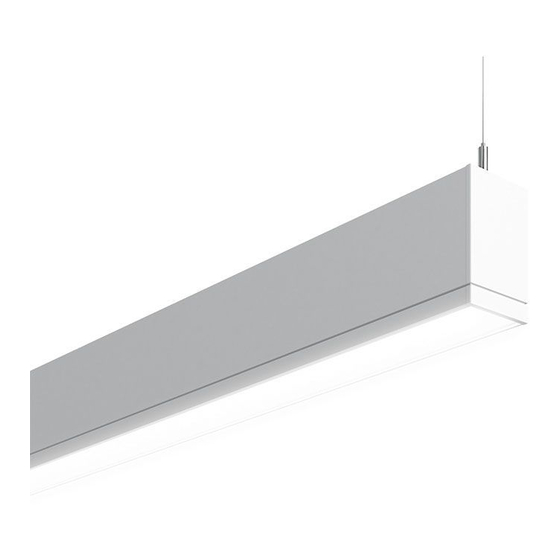
System Overview
These instructions review how to install TruGroove suspended fixtures. TruGroove 4ft, 6ft and 8ft modules
can be installed as individual standalone units, or they can be joined together to create continuous runs. The
graphics below show the components required to install a typical run of TruGroove suspended fixtures.
IMPORTANT: Read all instructions before beginning installation.
TruGroove Endcap Kit(s)
•
TG D/I endcap (x1)
•
Sling cable assembly (x1)
•
#8 sheet metal screws (x2)
•
#8-32 x 5/16" hex screw (x2)
•
Cable Strain Relief (x1) (Heyco
#7418)
•
1/2" Bushing (x1)
•
1/2" Plug (x1)
Module Lengths
TruGroove suspended fixtures come in 4ft, 6ft and 8ft modules.
Overall module lengths are shown below. Add 0.2" for each
endcap for accurate run length.
48"
4FT Module
72"
6FT Module
!
ATTENTION: Install in accordance with national and local building and electrical codes.
96"
8FT Module
Tools Required:
•
1/4" Nut Driver
•
Phillips Screwdriver
•
3/8" Nut Driver
•
Flat or #2 Robertson Screwdriver
Mount Spacing
TruGroove fixture modules are designed for exact on-grid mounting.
For non-accessible ceilings, mounts are adjustable within 5" of each
module end.
Up To 5" Adjustment
Mounts are adjustable to within 5" of module end(s).
TruGroove Joint Kit(s)
•
Sling cable assembly (x1)
•
Joiner aligner (x2)
•
Joiner biscuits (x2)
•
#8 sheet metal screws (x2)
•
#10-32 x 3/4" (x2)
•
#10-32 hex lock nut (x2)
•
Cable Strain Relief (x1)(Heyco
#7418)
•
1/2" Bushing (x1)
•
1/2" Plug (x1)
Up To 5" Adjustment
Page 1
Advertisement

Subscribe to Our Youtube Channel
Related Manuals for SIGNIFY LEDALITE TruGroove


Summary of Contents for SIGNIFY LEDALITE TruGroove
- Page 1 System Overview These instructions review how to install TruGroove suspended fixtures. TruGroove 4ft, 6ft and 8ft modules can be installed as individual standalone units, or they can be joined together to create continuous runs. The graphics below show the components required to install a typical run of TruGroove suspended fixtures. IMPORTANT: Read all instructions before beginning installation.
- Page 2 Arrange boxed fixture on floor in specified mounting location, remove fixtures from boxes. Install all ceiling mounting components and vertical aircraft cables using separate installation instruction for Aircraft Cable Mounting (supplied). Lens Removal Lens Removal Sling Mount Installation Sling Mount Installation Locking screws Symmetric Cross Section Asymmetric Cross Section...
-
Page 3: Corner Installation
Fixture Joining Fixture Joining Fixture Joining Fixture Joining #10-32 Nut Module 1 Module 2 Quick Wire Important: Use Wire Nuts ( Supplied By Connectors #10-32 Screw Others) At Power Feed Location (Supplied) Bring modules together and engage joiner Secure fixture modules together using the Raise module 2 to installed module 1 Ensure all connections are secure and all position. - Page 4 Corner Installation Corner Installation Closed Pattern Installation Asymmetric Outside Cross Section • To install a corner module, begin at step 3 of these instructions. • Follow the rest of the steps as required to attach power feed, join additional fixtures or attach endcaps.
-
Page 5: System Overview
System Overview These instructions review how to install TruGroove suspended fixtures. TruGroove 4ft, 6ft and 8ft modules can be installed as individual standalone units, or they can be joined together to create continuous runs. The graphics below show the components required to install a typical run of TruGroove suspended fixtures. IMPORTANT: Read all instructions before beginning installation. - Page 6 Arrange boxed fixture on floor in specified mounting location, remove fixtures from boxes. Install all ceiling mounting components and vertical aircraft cables using separate installation instruction for Aircraft Arrange boxed fixture on floor in specified mounting location, remove fixtures from boxes. Install all ceiling mounting components and vertical aircraft cables using separate installation instruction for Aircraft Cable Mounting (supplied).
- Page 7 Fixture Joining Fixture Joining Fixture Joining Quick-wire connectors (supplied) Module 2 Module 1 Important: Use Wire Nuts ( Supplied By Others) At Power Feed Location Bring modules together and engage joiner Ensure all connections are secure and all With fixtures modules supporting each bracket in module 1 on fixture bracket in wires are neatly tucked inside fixture other, complete wiring connections be-...
- Page 8 Factory Installed Trim Edge Of Textured Side Up Corner Mount Plug If Required After endcap is tightened, install 1/2” plug Insert 5/16” nut driver through 1/2” hole If a corner is required, it is recommended provided to seal top reflector. Trim plug in top reflector and tighten screw until the 2’X2’...
Need help?
Do you have a question about the LEDALITE TruGroove and is the answer not in the manual?
Questions and answers