Table of Contents
Advertisement
Advertisement
Table of Contents

Related Manuals for logitrans LOGITILT LT1001

Summary of Contents for logitrans LOGITILT LT1001
- Page 1 LOGITILT LT / LTS...
- Page 2 • Directive no. 2014/35/EC b) has been manufactured in conformance with the stipulations of the standard: • EN ISO 3691-5 Responsible for the technical dossier: Gitte Kirkegaard Name: Hillerupvej 35, DK-6760 Ribe Address: Signature: Gitte Kirkegaard, CEO, Logitrans A/S Ribe, 20.04.2020. B148 D177-4...
-
Page 3: Table Of Contents
Contents 1.0 Before the first lift....................4 2.0 Functions and identifications ................5 3.0 How to operate the Logitilt ................6 3.1 Pallet handling ........................6 3.2 Handle ..........................7 3.3 Brake ........................... 7 3.4 Remote control MR-1 / Lifting-Lowering-Tilting ..............8 3.5 Remote control / Lift and Lower / Tilt ................... -
Page 4: Before The First Lift
1.0 Before the first lift... The Logitilt is manufactured in accordance with safety directives. Among the subjects dealt with in this Instruction Manual are: • Proper application • Physical limitations of the product • Risks with improper use Therefore please read this Instruction Manual carefully! -
Page 5: Functions And Identifications
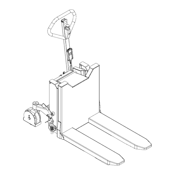
2.0 Functions and identifications Handle Lift / Lower Emergency stop Brake Remote control Setting of stop for tilting angle Battery indicator Fuses Name plate, serial number... -
Page 6: How To Operate The Logitilt
3.0 How to operate the Logitilt 3.1 Pallet handling For proper operation, stand behind the handle. Push/pull Raise/lower Tilt up/tilt down The Logitilt has assisted steering on one wheel to make manoeuvring easy. Note! The functions can be operated independently of each other. Lift/lower can be operated simultaneously with tilt. -
Page 7: Handle
3.0 How to operate the Logitilt 3.2 Handle When Logitilt is tilted, the handle can be turned to the side to make access to the crate easier. 3.3 Brake When the Logitilt is tilted, Logitilt must be standing on a firm and even floor with brake activated. -
Page 8: Remote Control Mr-1 / Lifting-Lowering-Tilting
3.0 How to operate the Logitilt 3.4 Remote control MR-1 / Lifting-Lowering-Tilting The remote control is used for: • Lifting/lowering the forks/load • Tiltning the forks/load 3.5 Remote control / Lift and Lower / Tilt Lift / Lower Press to lift. Press to lower. -
Page 9: Setting Of Stop For Tilting Angle
3.0 How to operate the Logitilt Tilt ATTENTION Check that the load is placed correctly and is evenly distributed, before tilting the load. Press for tilt in the direction of the arrow. 3.6 Setting of stop for tilting angle Increase tilting angle: Turn the ring towards the forks. -
Page 10: Optimum Safety
4.0 Optimum safety ATTENTION Moving parts Operation position... -
Page 11: Safety Regulations
4.0 Optimum safety 4.1 Safety regulations • Never walk under a tilted load! • Do not exceed the permitted capacity of the product. • Before lowering the forks, make certain that no foreign elements can hinder the free lowering of the forks. •... -
Page 12: Marking
4.0 Optimum safety 4.4 Marking The centre of gravity distance of the fork bracket is given on the data plate on the top of the bracket. Note that the centre of gravity does not remain in the same place. Its position varies as the forks are lowered or tilted. 4.5 Driving loaded The Logitilt is designed for use on even and level floor. -
Page 13: Emergency Braking
4.0 Optimum safety 4.6 Emergency braking If it becomes necessary to use the load as a brake to prevent the Logitilt running loose, activate the DOWN button quickly until the load reaches the ground. 4.7 Emergency stop The product has an emergency stop. When activating the emergency stop, the main current supply is switched off: •... -
Page 14: There Must Be A Current Supply
5.0 There must be a current supply... 5.1 Fuses - replacement The Logitilt has three fuses. Two are placed on the left side of the battery bracket. The main fuse is placed under the battery cover. Replacement: Before replacing fuse, disconnect battery + pole. The old fuse can then be removed and replaced by a new one of the same size. -
Page 15: Long Live Logitilt
6.0 Long live Logitilt... Regular inspection and the replacement of worn or defective parts in good time will prolong the life of the Logitilt. “Prevention is better than repair”, therefore ensure: • Correct usage • Regular cleaning • Periodic safety and service inspection 6.1 Lubrication and hydraulic oil Under normal conditions the Logitilt requires no lubrication. -
Page 16: Fork Adjustment
6.0 Long live Logitilt... 6.4 Fork adjustment Two of the rollers on the fork bracket are fitted on eccentric pins so that they can be adjusted.The adjustable rollers are uppermost. 1. Loosen set screw pos. 1 (5 mm key width). 2. -
Page 17: Good Service After Purchase
Such affected parts shall be sent to your Logitrans dealer carriage paid within the warranty period in force at the time in question, together with a copy of the documentation for the service performed (B0284 - see the back page). - Page 20 Periodic service and safety inspection Service check is required once each year. Safety inspection should be performed by the dealer or other qualified persons at least once each year, unless local regulations state otherwise. The inspections are to be performed on the basis of form no. B0278 and proved on form no.
Need help?
Do you have a question about the LOGITILT LT1001 and is the answer not in the manual?
Questions and answers