Advertisement
Advertisement
Table of Contents

Related Manuals for Vintage Vibe 200


Summary of Contents for Vintage Vibe 200
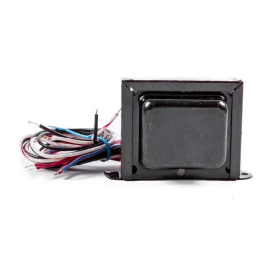
- Page 1 200 & 200A Wurlitzer Power Transformers...
- Page 2 TABLE OF CONTENTS P R I M A R Y W I R I N G S C H E M AT I C S ......P A G E 2 M O D E L 2 0 0 V I N TA G E A M P L I F I E R .
- Page 3 PRIMARY WIRING SCHEMATIC 120VAC LINE VOLTAGE 240VAC LINE VOLTAGE...
- Page 4 Model 200 Vintage Amplifier: Solder the transformer’s secondary wires to the corresponding locations on the amplifier PCB as indexed in the table below. TRANSFORMER WIRE AMPLIFIER PCB PIN #10 PIN#11 BLUE PIN #9 RED/YELLOW PIN #1 BOARD DIAGRAM...
- Page 5 Model 200A Vintage Amplifier: Solder the transformer’s secondary wires to the corresponding locations on the amplifier PCB as indexed in the table below. TRANSFORMER WIRE AMPLIFIER PCB PIN X1 PIN X2 BLUE PIN X3 RED/YELLOW PIN X4 BOARD DIAGRAM...
- Page 6 Vintage Vibe Classic 200 Amplifier: Solder the transformer’s secondary wires to the corresponding locations on the amplifier PCB as indexed in the table below. Transformer Wire Amplifier PCB “RED” “RED” Blue “BLUE” Red/Yellow “YEL” BOARD DIAGRAM...
- Page 7 Vintage Vibe 200A Wurly-Vibe Amplifier: Solder the transformer’s secondary wires to the corresponding locations on the amplifier PCB as indexed in the table below. Transformer Wire Amplifier PCB “R” “R” Blue “B” Red/Yellow “R/Y” BOARD DIAGRAM...
Need help?
Do you have a question about the 200 and is the answer not in the manual?
Questions and answers