Table of Contents
Advertisement
Quick Links
Advertisement
Table of Contents

Related Manuals for Vintage Vibe Wurly 200


Summary of Contents for Vintage Vibe Wurly 200
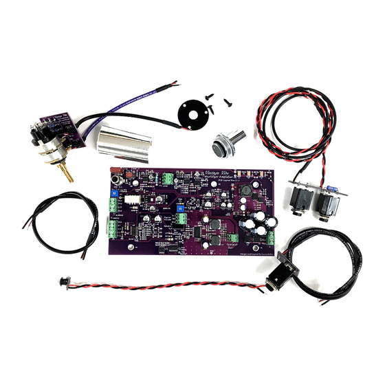
- Page 1 VINTAGE VIBE WURLY AMP KIT INSTALLATION / INSTRUCTION MANUAL...
- Page 2 If, after reviewing the material, you are not confident in your ability to successfully perform the installation, we recommend that you contact Vintage Vibe to discuss having us perform the service for you or a technician that you deem to be qualified.
-
Page 3: Table Of Contents
270) where the piano has been separated from the console (or, “chopped”) and if speakers are present, they are model 200A type and have been installed in the lid. There are no provisions or instructions for utilizing the console portions of these models. Vintage Vibe Rev: 1.0 Wurly Amp Manual... -
Page 4: Controls / Features
VINTAGE VIBE – WURLY AMP – CONTROLS / FEATURES 1. Volume: Your stock volume potentiometer will serve as the Master Volume control for both the Speaker / Headphone Output and Aux Output. 2. Outer Tremolo Knob: Controls the depth of the tremolo. When set fully counter clockwise the effect is bypassed. - Page 5 Master Volume control. It should be adjusted so that, when the Master Volume is set fully clockwise, playing at hardest dynamics does not produce distortion from the speakers. Vintage Vibe Rev: 1.0 Wurly Amp Manual MAY 2020...
- Page 6 Tip = Send Ring = Return Shield = Ground Utilizing either a Y/Insert Cable or appropriate breakout box, connect your desired effects. The FX loop is located prior to the tremolo circuitry. Vintage Vibe Rev: 1.0 Wurly Amp Manual MAY 2020...
-
Page 7: Universal Installation Instructions
VINTAGE VIBE WURLY AMP INSTALLATION INSTRUCTIONS Models 200/200A and Chopped Consoles 1. Ensure that the piano is unplugged from the wall outlet and that all voltage has been drained from the stock amplifier. Remove electronics rail from piano. *For 200A pianos, save the screw that secured the AC inlet “earth ground” wire to the rail as you will need to re-install this at the end of the installation. - Page 8 5. - Desolder or clip the Orange wire at the Headphone Jack. - Desolder or clip the Black wire at the Headphone Jack terminal strip. *The opposite ends of these wires will be coming from: Vintage Vibe Rev: 1.0 Wurly Amp Manual...
- Page 9 Speaker. Determine which wire’s other end terminates at the stock amplifier PCB and desolder or clip it from the speaker terminal. *There should still be an Orange Wire and a Black Wire connected between the two speakers. Vintage Vibe Rev: 1.0 Wurly Amp Manual MAY 2020...
- Page 10 - Remove Aux Output Trimpot from piano base. 9. - Temporarily remove cable clamps from rail to remove Jack and Potentiometer wiring. - Reinstall cable clamp and AC terminal strip. 10. Remove stock amplifier PCB. 200 Amplifier: Vintage Vibe Rev: 1.0 Wurly Amp Manual MAY 2020...
- Page 11 - Desolder primary wires from AC terminal strip. 200A Model Only: - Remove wires from tube. - Unscrew metal bracket and remove tube (the tube is also spot glued to the rail). Vintage Vibe Rev: 1.0 Wurly Amp Manual MAY 2020...
- Page 12 - Resolder primary wires to the correct lugs of the AC terminal strip. *If installing fuse mod – replace existing fuse at terminal strip with new fuse holder. Vintage Vibe Rev: 1.0 Wurly Amp Manual MAY 2020...
- Page 13 - Drill out the revealed hole with a 1/4” bit and remove any burrs. - Install LED Bezel through the front of the control bracket. 13. Install new Vintage Vibe Wurly Amp PCB on rail using existing screws. 200 Amplifier Rail: 5 screws 200A Amplifier Rail: 4 screws 14.
- Page 14 - Connect the other end of the cable to PCB connector J4: PCB: J4 Cable Black Wire Red Wire Heatshrinked Shield 16. Install Tremolo Potentiometer PCB and Cabling: - Install Tremolo Potentiometer PCB using included lock washer and nut. Vintage Vibe Rev: 1.0 Wurly Amp Manual MAY 2020...
- Page 15 17. If installing LED indicator: - Install LED into bezel from rear (ensure PCB solder pads do not touch bracket) - Connect wires to PCB connector J2: PCB: J2 Wiring Red Wire Black Wire Vintage Vibe Rev: 1.0 Wurly Amp Manual MAY 2020...
-
Page 16: Model 200/200A Aux Out
Orange Wire SPKR- Black Wire - Install Jack PCB into bracket using included hardware. Do NOT over-torque. - Route cabling around rear of rail and through cable clamp at AC Terminal Strip. Vintage Vibe Rev: 1.0 Wurly Amp Manual MAY 2020... - Page 17 Wires from Jack PCB Speaker Out + Red Wire Speaker Out - Black Wire 2. Reinstall remaining cable clamp with all wires through it except for those coming from the Tremolo PCB. Vintage Vibe Rev: 1.0 Wurly Amp Manual MAY 2020...
- Page 18 5. 200A Model Only: - Connect speaker wiring Molex plug and socket. If Installing FX Loop Option refer to that section now. Otherwise refer to the Final Steps / Set Up section. Vintage Vibe Rev: 1.0 Wurly Amp Manual MAY 2020...
-
Page 19: Chopped Console Model Aux Out
Red Wire Speaker Out - Black Wire - Disconnect the Molex connectors from the other pair of wires. - Solder the free ends of the wires to the Right Speaker Lugs: Vintage Vibe Rev: 1.0 Wurly Amp Manual MAY 2020... - Page 20 5. - Install new Headphone Jack assembly into the plate at front right cheek block of the piano. - Use provided 1/4" cable clamp to hold wires in place with front right rail mounting screw. Vintage Vibe Rev: 1.0 Wurly Amp Manual MAY 2020...
- Page 21 6. Finish rail installation. 7. Connect speaker wiring Molex plug and socket. If Installing FX Loop Option refer to that section now. Otherwise refer to the Final Steps / Set Up section. Vintage Vibe Rev: 1.0 Wurly Amp Manual MAY 2020...
-
Page 22: Final Steps / Set Up
Out (PCB connector J5) as part of the installation, set the Level Adjust trimmer to the fully clockwise position. - Then set Aux Output trimmer for desired output level to interface with an amplifier, PA, DI, etc. Vintage Vibe Rev: 1.0 Wurly Amp Manual MAY 2020... -
Page 23: Rca Cable Replacement
PCB. 200: 1. Remove screw securing coax cable shield and ground jumper wire to harp. 2. Clip coax conductor wire away from terminal lug. Do NOT cut jumper wire. Vintage Vibe Rev: 1.0 Wurly Amp Manual MAY 2020... - Page 24 3. Add the new cable’s conductor terminal lug to the harp at the same location as the existing jumper wire lug. 4. Screw down the new cable’s shield terminal lug along with the ground jumper lug removed earlier. Vintage Vibe Rev: 1.0 Wurly Amp Manual MAY 2020...
-
Page 25: Fx Loop Installation
- Install in front left or right cheek block cavity. Chopped Consoles – additional drilling required: - Install at right side of piano in mirrored location of 200A Aux Output Trim pot (see picture above). Vintage Vibe Rev: 1.0 Wurly Amp Manual MAY 2020... - Page 26 - Paint your newly drilled hole flat black. Allow to dry. 5. With FX Loop Jack PCB installed into plate so that none of the mounting holes are obscured by the PCB: Vintage Vibe Rev: 1.0 Wurly Amp Manual MAY 2020...
- Page 27 - Install the three mounting screws provided. Two of the screws can be installed with the screwdriver entering from the side, the remainder will require the screwdriver enter through the harp from above. Vintage Vibe Rev: 1.0 Wurly Amp Manual...
- Page 28 9. If you wish to remove the FX loop at any time, simply install a short jumper wire between the Top and Bottom terminals of PCB Connector J7. This will complete the loop and restore normal operation. Vintage Vibe Rev: 1.0 Wurly Amp Manual...
- Page 29 Vintage Vibe Rev: 1.0 Wurly Amp Manual MAY 2020...
-
Page 30: Additional Notes
1. It is highly recommended for the best performance and lowest possible noise that reed bar shields be utilized in conjunction with the Vintage Vibe Wurly Amp. Reed bar shields were only installed at the factory into “A” suffix model units: 200A, 206A, 214A, etc.
Need help?
Do you have a question about the Wurly 200 and is the answer not in the manual?
Questions and answers