Table of Contents
Advertisement
1) Warnings
DO NOT OPEN WHEN AN EXPLOSIVE
ATMOSPHERE IS PRESENT
DO NOT OPEN WHEN ENERGISED
POTENTIAL ELECTROSTATIC CHARGING
HAZARD - CLEAN ONLY WITH A DAMP
CLOTH
HIGH VOLTAGE SHOCK HAZARD. WAIT 5
MINUTES AFTER REMOVING POWER
BEFORE OPENING THE ENCLOSURE
DO NOT PAINT
TO REDUCE THE RISK OF IGNITION OF
HAZARDOUS ATMOSPHERES, THE FIRST
CONDUIT RUN MUST HAVE A SEALING
FITTING CONNECTED WITHIN 18 INCHES
OF ENCLOSE. SUBSEQUENT CONDUIT
RUNS MUST HAVE A SEALING FITTING
CONNECTED AS CLOSE AS PRACTICAL TO
THE WALL OF THE ENCLOSURE, BUT IN
NO CASE MORE THAN THE SIZE OF THE
CONDUIT OR 50MM, WHICHEVER IS THE
LESSER.
TO PREVENT IGNITION OF GROUP A, B, C
AND D ATMOSPHERES - SEE
INSTRUCTION FOR CHEMICAL
COMPATIBILITY
Avertissement:
NE PAS OUVRIR UN PRESENCE
D'ATMOSPHERE EXPLOSIVE
NE PAS OUVRIR ENERGIE
DANGER POTENTIEL CHARGE
ÉLECTROSTATIQUE - NETTOYER
UNIQUEMENT AVEC UN CHIFFON HUMIDE
HAUT TENSION, RISK DE CHOC.
ATTENDEZ 5 MINUTES APRES AVOIR
DEBRANCHE L'ALIMENTATION AVANT
D'OUVRIR LA BOITIER
NE PAS PEINTURER
POUR RÉDUIRE LE RISQUE
D'INFLAMMATION DES ATMOSPHÈRES
DANGEREUSES, LE PREMIER CONDUIT DE
CONDUIT DOIVENT AVOIR UN RACCORD
D'ÉTANCHÉITÉ RACCORDÉ À MOINS DE 18
POUCES DE L'ENFERMEMENT. POUR
SUBSÉQUENT LES CONDUITES DE
CONDUIT LA DISTANCE ENTRE LA
SURFACE DE LA MASSE DE REMPLISSAGE
_______________________________________________________________________________________________________________________________
European Safety Systems Ltd. Impress House, Mansell Road, Acton, London W3 7QH
Document No. D191-00-601-IS
INSTRUCTION MANUAL (ATEX/IECEx/SIL2)
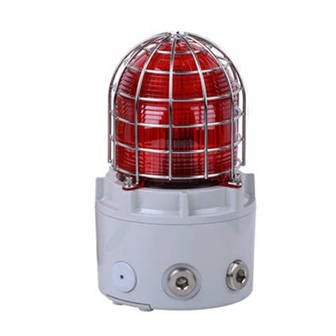
D1xB2X05, D1xB2X10, D1xB2X15 SIL 2 Xenon Beacons
For use in Hazardous Locations
Issue 1
20-03-2020
AU PLUS PRÈS DE L'ENVELOPPE DOIT
ÊTRE AUSSI PETITE QUE CE QUI EST
RÉALISABLE MAIS EN AUCUN CAS
SUPÉRIEURE À LA PLUS PETITE DES
DIMENSIONS CORRESPONDANT À LA
TAILLE DU CONDUIT OU À 50 MM.
POUR PRÉVENIR L'INFLAMMATION DES
ATMOSPHÈRES DES GROUPES A, B, C ET
D-VOIR L'INSTRUCTION POUR LA
COMPATIBILITÉ CHIMIQUE
2) Rating & Marking Information
2.6 ATEX / IECEx certification
The D1xB2X Xenon beacons comply with the following
standards:
EN IEC60079-0:2018 / IEC60079-0:2017 (Ed 7)
EN60079-1:2014 / IEC60079-1 (Ed. 7) (2014)
EN60079-31:2014 / IEC60079-31 (Ed. 2) (2013)
The D1xB2X05DC024 Xenon Beacons are rated as follows:
Ex db IIC T4 Gb Ta -55°C to +80°C
Ex db IIC T5 Gb Ta -55°C to +75°C
Ex db IIC T6 Gb Ta -55°C to +60°C
Ex tb IIIC T104°C Db Ta -55°C to +80°C
The D1xB2X10DC024 Xenon Beacons are rated as follows:
Ex db IIC T4 Gb Ta -55°C to +80°C
Ex db IIC T5 Gb Ta -55°C to +45°C
Ex tb IIIC T135°C Db Ta -55°C to +80°C
The D1xB2X15DC024 Xenon Beacons are rated as follows:
Ex db IIC T3 Gb Ta -55°C to +80°C
Ex db IIC T4 Gb Ta -55°C to +65°C
Ex tb IIIC T146°C Db Ta -55°C to +80°C
Certificate No.
DEMKO 19 ATEX 2009X
IECEx ULD 19.0006X
ATEX Mark, Equipment
Group and Category:
CE Marking
Notified Body No.:
The units can be installed in locations with the following
conditions:
Area Classification:
Explosive gas air mixture likely to occur in
Zone 1
normal operation.
Explosive gas air mixture not likely to occur
Zone 2
in normal operation, and if it does, it will only
exist for a short time.
sales@e2s.com
www.e2s.com
Sheet 1 of 8
II 2G
II 2D
2813
Tel: +44 (0)208 743 8880
Fax: +44 (0)208 740 4200
Advertisement
Table of Contents

Related Manuals for E2S D1xB2X Series


Summary of Contents for E2S D1xB2X Series
- Page 1 SURFACE DE LA MASSE DE REMPLISSAGE exist for a short time. _______________________________________________________________________________________________________________________________ European Safety Systems Ltd. Impress House, Mansell Road, Acton, London W3 7QH sales@e2s.com Tel: +44 (0)208 743 8880 www.e2s.com Fax: +44 (0)208 740 4200 Document No. D191-00-601-IS...
-
Page 2: Special Conditions Of Use
18 inches from the enclosure. necessary capacity to provide the input current to all the units. _______________________________________________________________________________________________________________________________ European Safety Systems Ltd. Impress House, Mansell Road, Acton, London W3 7QH sales@e2s.com Tel: +44 (0)208 743 8880 www.e2s.com Fax: +44 (0)208 740 4200 Document No. -
Page 3: Location And Mounting
This can be achieved by unscrewing the glass dome cover, taking extreme care not to damage the threads when doing _______________________________________________________________________________________________________________________________ European Safety Systems Ltd. Impress House, Mansell Road, Acton, London W3 7QH sales@e2s.com Tel: +44 (0)208 743 8880 www.e2s.com Fax: +44 (0)208 740 4200 Document No. -
Page 4: Cable Connections
Fig. 8: Internal and External Earth Locations The resistor must be connected directly across the +ve and _______________________________________________________________________________________________________________________________ European Safety Systems Ltd. Impress House, Mansell Road, Acton, London W3 7QH sales@e2s.com Tel: +44 (0)208 743 8880 www.e2s.com Fax: +44 (0)208 740 4200 Document No. -
Page 5: Maintenance, Overhaul & Repair
The Beacon lens cover is interchangeable, contact E2S Ltd for a replacement lens cover available in various colours. To change the lens cover, unscrew the 4-off M5 socket head screws, spring and flat washers using a 4mm Hex key. - Page 6 Active mode where it will start to The new SIL 2 version of the E2S D1XB2X05, D1XB2X10 & function/flash. When testing the system and beacons D1XB2X15 Xenon strobe beacon are designed, tested and operation, the system is put into Active mode.
- Page 7 :- The fault indication signal on TB1 can take up to 1.5 seconds to indicate system fault. _______________________________________________________________________________________________________________________________ European Safety Systems Ltd. Impress House, Mansell Road, Acton, London W3 7QH sales@e2s.com Tel: +44 (0)208 743 8880 www.e2s.com Fax: +44 (0)208 740 4200 Document No.
- Page 8 Figure 6 – Schematic of SIL 2 system wiring for fault detection in standby and active mode – 4 wire installation _______________________________________________________________________________________________________________________________ European Safety Systems Ltd. Impress House, Mansell Road, Acton, London W3 7QH sales@e2s.com Tel: +44 (0)208 743 8880 www.e2s.com Fax: +44 (0)208 740 4200 Document No.
-
Page 9: Multiple Unit Configuration
_______________________________________________________________________________________________________________________________ European Safety Systems Ltd. Impress House, Mansell Road, Acton, London W3 7QH sales@e2s.com Tel: +44 (0)208 743 8880 www.e2s.com Fax: +44 (0)208 740 4200 Document No. - Page 10 If the customer chooses to use this configuration within their system, it must be noted that the factory default settings for the unit does not have an EOL resistor installed. The customer can request E2S to install an EOL resistor and this will be depicted in the product code.
- Page 11 5.5mA Star & EOL = 3.3kΩ Table 3 _______________________________________________________________________________________________________________________________ European Safety Systems Ltd. Impress House, Mansell Road, Acton, London W3 7QH sales@e2s.com Tel: +44 (0)208 743 8880 www.e2s.com Fax: +44 (0)208 740 4200 Document No. D191-00-601-IS Issue 1 20-03-2020 Sheet 11 of 8...
- Page 12 _______________________________________________________________________________________________________________________________ European Safety Systems Ltd. Impress House, Mansell Road, Acton, London W3 7QH sales@e2s.com Tel: +44 (0)208 743 8880 www.e2s.com Fax: +44 (0)208 740 4200 Document No.
- Page 13 TB Fault resistor & RLY 1-2 in Figure 9: J2 Header settings _______________________________________________________________________________________________________________________________ European Safety Systems Ltd. Impress House, Mansell Road, Acton, London W3 7QH sales@e2s.com Tel: +44 (0)208 743 8880 www.e2s.com Fax: +44 (0)208 740 4200 Document No.
- Page 14 _______________________________________________________________________________________________________________________________ European Safety Systems Ltd. Impress House, Mansell Road, Acton, London W3 7QH sales@e2s.com Tel: +44 (0)208 743 8880 www.e2s.com Fax: +44 (0)208 740 4200 Document No. D191-00-601-IS Issue 1 20-03-2020 Sheet 14 of 8...
- Page 15 J7 Header Pin - Postion B (pins 2 & 3 linked) set for hard reset. Fig 10 – Jumper Settings _______________________________________________________________________________________________________________________________ European Safety Systems Ltd. Impress House, Mansell Road, Acton, London W3 7QH sales@e2s.com Tel: +44 (0)208 743 8880 www.e2s.com Fax: +44 (0)208 740 4200 Document No. D191-00-601-IS...
- Page 16 Figure 11: Schematic of SIL 2 system wiring for fault detection in standby mode only – 4 wire installation configuration wired in series _______________________________________________________________________________________________________________________________ European Safety Systems Ltd. Impress House, Mansell Road, Acton, London W3 7QH sales@e2s.com Tel: +44 (0)208 743 8880 www.e2s.com Fax: +44 (0)208 740 4200 Document No.
- Page 17 Figure 12: Schematic of SIL 2 system wiring for fault detection in standby mode only – 4 wire installation configuration in Star formation _______________________________________________________________________________________________________________________________ European Safety Systems Ltd. Impress House, Mansell Road, Acton, London W3 7QH sales@e2s.com Tel: +44 (0)208 743 8880 www.e2s.com Fax: +44 (0)208 740 4200 Document No.
- Page 18 Figure 13: Schematic of SIL 2 system wiring for fault detection in standby mode only – 2 wire installation configuration wired in series _______________________________________________________________________________________________________________________________ European Safety Systems Ltd. Impress House, Mansell Road, Acton, London W3 7QH sales@e2s.com Tel: +44 (0)208 743 8880 www.e2s.com Fax: +44 (0)208 740 4200 Document No.
- Page 19 Figure 14: Schematic of SIL 2 system wiring for fault detection in standby mode only – 2 wire installation configuration in star formation _______________________________________________________________________________________________________________________________ European Safety Systems Ltd. Impress House, Mansell Road, Acton, London W3 7QH sales@e2s.com Tel: +44 (0)208 743 8880 www.e2s.com Fax: +44 (0)208 740 4200 Document No.
Need help?
Do you have a question about the D1xB2X Series and is the answer not in the manual?
Questions and answers