Table of Contents
Advertisement
Quick Links
MIDDLE STATIC PRESSURE DUCT TYPE AIR CONDITIONER
Owner's Manual &
Installation Manual
IMPORTANT NOTE:
Read this manual carefully before installing
or operating your new air conditioning
unit. Make sure to save this manual for
future reference.
Please check the applicable models, technical
data, F-GAS(if any) and manufacturer information
from the "Owner's Manual - Product Fiche "
in the packaging of the outdoor unit.
(European Union products only)
Advertisement
Table of Contents

Subscribe to Our Youtube Channel
Related Manuals for ACPro M Series


Summary of Contents for ACPro M Series
- Page 1 MIDDLE STATIC PRESSURE DUCT TYPE AIR CONDITIONER Owner’s Manual & Installation Manual IMPORTANT NOTE: Read this manual carefully before installing or operating your new air conditioning unit. Make sure to save this manual for future reference. Please check the applicable models, technical data, F-GAS(if any) and manufacturer information from the “Owner's Manual - Product Fiche ”...
-
Page 2: Table Of Contents
Table of Contents ................04 Safety Precautions Owner’s Manual ............08 Unit Specifications and Features 1. Indoor unit ...................................08 2. Operating temperature..............................09 3. Other features ..................................10 ..............11 Care and Maintenance ................13 Troubleshooting... - Page 3 Installation Manual ....................16 Accessories ................17 Installation Summary ....................18 Unit Parts ...............19 Indoor Unit Installation 1. Select installation location..............................19 2. Hang indoor unit..................................20 3. Duct and accessories installation............................22 4. Adjust the air inlet direction..............................22 5. Fresh air duct installation................................23 6. Motor and drain pump maintenance..........................23 7.
-
Page 4: Safety Precautions
Safety Precautions Read Safety Precautions Before Operation and Installation Incorrect installation due to ignoring instructions can cause serious damage or injury. The seriousness of potential damage or injuries is classified as either a WARNING or CAUTION. CAUTION WARNING This symbol indicates the possibility of This symbol indicates the possibility of personnel injury or loss of life. - Page 5 CLEANING AND MAINTENANCE WARNINGS Turn o the device and disconnect the power before cleaning. Failure to do so can cause electrical shock. Do not clean the air conditioner with excessive amounts of water. Do not clean the air conditioner with combustible cleaning agents. Combustible cleaning agents can cause re or deformation.
-
Page 6: Owner's Manual
WARNINGS FOR PRODUCT INSTALLATION 1. Installation must be performed by an authorized dealer or specialist. Defective installation can cause water leakage, electrical shock, or re. 2. Installation must be performed according to the installation instructions. Improper installation can cause water leakage, electrical shock, or re. (In North America,installation must be performed in accordance with the requirement of NEC and CEC by authorized personnel only.) 3. - Page 7 WARNING for Using R32/R290 Refrigerant When ammable refrigerant are employed, appliance shall be stored in a well -ventilated area where the room size corresponds to the room area as speci ec for operation. For R32 frigerant models: Appliance shall be installed, operated and stored in a room with a oor area larger than X m²...
-
Page 8: Unit Specifications And Features
Unit Specifications and Features Indoor unit NOTE: Di erent models have di erent display panel. Not all the indicators describing below are available for the air conditioner you purchased. Please check the indoor display panel of the unit you purchased. Illustrations in this manual are for explanatory purposes. -
Page 9: Operating Temperature
Display panel Timer Infrared indicator receiver Manual LED display button Operation Alarm indicator indicator PRE-DEF (pre-heating/defrost) indicator MANUAL button : This button selects the mode in the following order: AUTO, FORCED COOL, OFF. FORCED COOL mode : In FORCED COOL mode, the Operation light flashes. The system will then turn to AUTO after it has cooled with a high wind speed for 30 minutes. -
Page 10: Other Features
Fixed-speed Type COOL mode DRY mode HEAT mode 0°C-30°C Room 17°C-32°C (62°F-90°F) 10°C-32°C (50°F-90°F) Temperature (32°F-86°F) 18°C-43°C (64°F-109°F) 11°C-43°C (52°F-109°F) -7°C-43°C (19°F-109°F) Outdoor -7°C-24°C 18°C-43°C (64°F-109°F) (For models with low-temp cooling systems) Temperature (19°F-75°F) 18°C-52°C (64°F-126°F) 18°C-52°C (64°F-126°F) (For special tropical models) (For special tropical models) NOTE: Room relative humidity less than 80%. -
Page 11: Care And Maintenance
Care and Maintenance 3. Remove the air lter. Cleaning Your Indoor Unit 4. Clean the air lter by vacuuming the surface or washing it in warm water with mild BEFORE CLEANING OR detergent. MAINTENANCE 5. Rinse the lter with clean water and allow it ALWAYS TURN OFF YOUR AIR CONDITIONER DO NOT to air-dry. - Page 12 Maintenance – If using water, the inlet side If using a vacuum cleaner, should face down and away the inlet side should face Long Periods of Non-Use from the water stream. the vacuum. If you plan not to use your air conditioner for an extended period of time, do the following: CAUTION Before changing the lter or cleaning,...
-
Page 13: Troubleshooting
Troubleshooting SAFETY PRECAUTIONS If any of the following conditions occurs, turn o your unit immediately! The power cord is damaged or abnormally warm You smell a burning odor The unit emits loud or abnormal sounds A power fuse blows or the circuit breaker frequently trips Water or other objects fall into or out of the unit DO NOT ATTEMPT TO FIX THESE YOURSELF! CONTACT AN AUTHORIZED SERVICE PROVIDER IMMEDIATELY! - Page 14 Issue Possible Causes The outdoor unit The unit will make di erent sounds based on its current operating mode. makes noises Dust is emitted from The unit may accumulate dust during extended periods of non-use, which will be either the indoor or emitted when the unit is turned on.
- Page 15 Problem Possible Causes Solution Wait for the power to be restored Power failure The power is turned o Turn on the power The unit is not The fuse is burned out Replace the fuse working Replace batteries Remote control batteries are dead The Unit’...
-
Page 16: Accessories
Accessories The air conditioning system comes with the following accessories. Use all of the installation parts and accessories to install the air conditioner. Improper installation may result in water leakage, electrical shock and re, or cause the equipment to fail. The items are not included with the air conditioner must be purchased separately. -
Page 17: Installation Summary
Installation Summary Install the indoor unit Install the drainpipe Install the outdoor unit Evacuate the refrigeration Connect the wires Connect the refrigerant system pipes Perform a test run... -
Page 18: Unit Parts
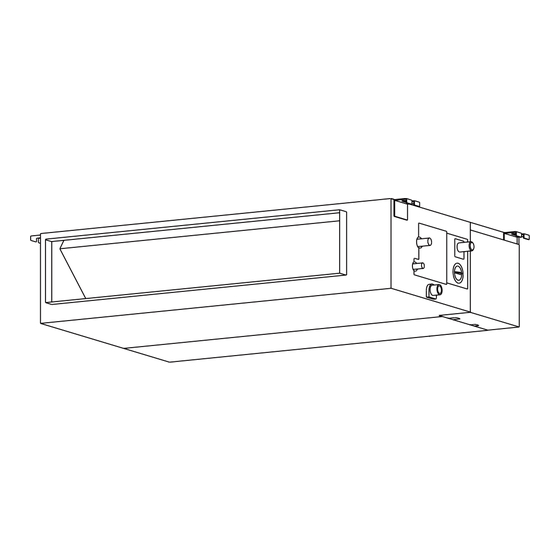
Unit Parts NOTE: The installation must be performed in accordance with the requirement of local and national standards. The installation may be slightly di erent in di erent areas. Air outlet Air inlet Electric control cabinet Drain pipe Connecting pipe Air inlet Air outlet NOTE ON ILLUSTRATIONS... -
Page 19: Indoor Unit Installation
Indoor Unit Installation Installation Instructions – Indoor unit NOTE: Panel installation should be performedafter piping and wiring have been completed. install unit in the following Step 1: Select installation location DO NOT locations: Before installing the indoor unit, you must choose an appropriate location. -
Page 20: Hang Indoor Unit
Step 2: Hang indoor unit. 1. Please refer to the following diagrams to locate the four positioning screw bolt holes on the ceiling. Be sure to mark the paces where you will drill ceiling hook holes. Air outlet dimensions Air inlet dimensions Air lter Descending ventilation opening and mounted hook Air lter... - Page 21 Wood 3. Install hanging screw bolts. Cut o the roof beam. Place the wood mounting across the roof beam, then install the hanging screw bolts. Strengthen the point at which the cut was made. Consolidate the roof beam. Wood mounting 4.
-
Page 22: Duct And Accessories Installation
1. Take o the ventilation panel and ange. Step 3: Duct and accessories installation 1. Install the lter (optional) according to the size Air return ange of the air inlet. 2. Install the canvas tie-in between the body and duct. 3. -
Page 23: Fresh Air Duct Installation
Step 5: Fresh air duct installation Pump maintainance: Remove four screws from the drain pump. Dimension : Duct joint for fresh air Unplug the pump power supply and water level switch cable. Detach the pump. MODLE 9-12 Ø92mm(3.62”) Ø113mm(4.45”) Pump Step 7: Drill wall hole for connective piping 1. -
Page 24: Connect Drain Hose
NOTE ON DRAINPIPE INSTALLATION Step 8: Connect drain hose When using an extended drainpipe, The drainpipe is used to drain water away from tightenthe indoor connection with an the unit. Improper installation may cause unit additionalprotection tube. This prevents and property damage. it from pulling loose. - Page 25 Units with a pump. 3. Pass the drain hose through the wall hole. Make sure the water drains to a safe location 1. Remove the test cover. where it will not cause water damage or a Fill the water pan with 2 liters of water. slipping hazard.
-
Page 26: Outdoor Unit Installation
Outdoor Unit Installation install unit in the following locations: DO NOT Install the unit by following local codes and Near an obstacle that will block air inlets regulations , there may be di er slightly and outlets between di erent regions. Near a public street, crowded areas, or where noise from the unit will disturb others Near animals or plants that will be harmed... -
Page 27: Install Drain Joint
Step 3: Anchor outdoor unit Step 2: Install drain joint(Heat pump unit only) The outdoor unit can be anchored to the Before bolting the outdoor unit in place, you must install the drain joint at the bottom of the unit. ground or to a wall-mounted bracket with Note that there are two di erent types of drain bolt(M10). - Page 28 (unit: mm/inch) Outdoor Unit Dimensions Mounting Dimensions W x H x D Distance A Distance B 760x590x285 (29.9x23.2x11.2) 530 (20.85) 290 (11.4) 810x558x310 (31.9x22x12.2) 549 (21.6) 325 (12.8) 845x700x320 (33.27x27.5x12.6) 560 (22) 335 (13.2) 900x860x315 (35.4x33.85x12.4) 590 (23.2) 333 (13.1) 945x810x395 (37.2x31.9x15.55) 640 (25.2) 405 (15.95)
-
Page 29: Refrigerant Piping Connection
Refrigerant Piping Connection do not When connecting refrigerant piping, let substances or gases other than the speci ed refrigerant enter the unit. The presence of other gases or substances will lower the unit’ s capacity, and can cause abnormally high pressure in the refrigeration cycle. This can cause explosion and injury. -
Page 30: Connection Instructions -Refrigerant Piping
CAUTION Connection Instructions – Refrigerant Piping If the outdoor unit is installed higher than the indoor unit: CAUTION -It is recommended that vertical suction risers The branching pipe must be installed not be upsized. Proper oil return to the horizontally. An angle of more than 10° may compressor should be maintained with suction cause malfunction. -
Page 31: Flare Pipe Ends
2. Using a reamer or deburring tool, remove Turn the handle of the aring tool clockwise until the pipe is fully ared. Flare all burrs from the cut section of the pipe. the pipe in accordance with the dimensions. Pipe PIPING EXTENSION BEYOND FLARE FORM Reamer Pipe... -
Page 32: Wiring
6. After connecting the copper pipes to the indoor unit, wrap the power cable, signal cable and the piping together with binding tape. NOTE: DO NOT intertwine signal cable with other wires. While bundling these items together, do not intertwine or cross the signal cable with any other wiring. - Page 33 Air switch 8. Make sure to properly ground the air (purchased seperately) conditioner. 9. Every wire must be rmly connected. Indoor & Outdoor Outdoor unit power wires Loose wiring can cause the terminal to connective wires overheat, resulting in product malfunction (purchased seperately) and possible re.
-
Page 34: Outdoor Uint Wiring
Outdoor Unit Wiring 3. Connect the u-lugs to the terminals Match the wire colors/labels with the labels WARNING on the terminal block. Firmly screw the u-lug of each wire to its corresponding terminal. Before performing any electrical or wiring 4. Clamp down the cable with the cable clamp. work, turn o the main power to the 5. -
Page 35: Power Speci Cations
CAUTION While connecting the wires, please strictly follow the wiring diagram. The refrigerant circuit can become very hot. Keep the interconnection cable away from the copper tube. 4. Clamp down the cable with the cable clamp.The cable must not be loose or pull on the u-lugs. 5. - Page 36 Independent Power Supply Specifications MODEL 19K~24K 25K~36K 37K~48K 49K~60K (Btu/h) PHASE 1 Phase 1 Phase 1 Phase 1 Phase 1 Phase POWER (indoor) 208-240V 208-240V 208-240V 208-240V 208-240V VOLT CIRCUIT BREAKER/ 15/10 15/10 15/10 15/10 15/10 FUSE(A) PHASE 1 Phase 1 Phase 1 Phase 1 Phase...
-
Page 37: Air Evacuation
Air Evacuation Preparations and Precautions Close the Low Pressure side of the manifold gauge, and turn o the vacuum pump. Air and foreign matter in the refrigerant circuit can Wait for 5 minutes, then check that there cause abnormal rises in pressure, which can damage has been no change in system pressure. -
Page 38: Note On Adding Refrigerant
Note on Adding Refrigerant Some systems require additional charging depending on pipe lengths. The standard pipe length varies according to local regulations. For example, in North America, the standard pipe length is 7.5m (25’). In other areas, the standard pipe length is 5m (16‘). The refrigerant should be charged from the service port on the outdoor unit’... -
Page 39: Test Run
Test Run Before Test Run f. Check to see that the drainage system is unimpeded and draining smoothly. A test run must be performed after the entire g. Ensure there is no vibration or abnormal system has been completely installed. Confirm noise during operation.
Need help?
Do you have a question about the M Series and is the answer not in the manual?
Questions and answers