Table of Contents
Advertisement
Quick Links
h2000 Autopilot
User Manual
!
WARNING
The use of solvent based or chemical
cleaners on the Pilot Displays will result
in damage and invalidate your warranty.
Premier Way
Abbey Park, Romsey
Hampshire, SO51 9DH, UK
www.BandG.com
© B&G Ltd. 2004
The copyright of this manual is the property of B&G Ltd.
HB-0842-04
Advertisement
Chapters
Table of Contents

Related Manuals for Simrad B&G h2000


Summary of Contents for Simrad B&G h2000
- Page 1 h2000 Autopilot User Manual WARNING The use of solvent based or chemical cleaners on the Pilot Displays will result in damage and invalidate your warranty. Premier Way Abbey Park, Romsey Hampshire, SO51 9DH, UK www.BandG.com © B&G Ltd. 2004 The copyright of this manual is the property of B&G Ltd. HB-0842-04...
- Page 2 Intentionally Left Blank...
- Page 3 h2000 Autopilot User Manual h2000 AUTOPILOT USER MANUAL CONTENTS Product Liability and Safety Warnings PART 1 INTRODUCTION PART 2 OPERATING INFORMATION PART 3 CALIBRATION PART 4 INSTALLATION INFORMATION PART 5 OPTIONS PART 6 DIAGNOSTIC DATA HB-0842-04...
- Page 4 h2000 Autopilot User Manual PRODUCT LIABILITY AND SAFETY WARNINGS PRODUCT LIABILITY: Brookes and Gatehouse Ltd. accept no responsibility for the use and/or operation of this equipment. It is the users’ responsibility to ensure that under all circumstances the equipment is used for the purposes for which it has been designed. WARNING - ELECTRICAL HAZARD: This equipment uses high voltage electrical power.
-
Page 5: Table Of Contents
h2000 Autopilot User Manual Part 1 - Introduction PART 1 - INTRODUCTION CONTENTS Para Page SYSTEM OVERVIEW AUTOPILOT OPERATION CONTROLLING THE AUTOPILOT AUTOPILOT DISPLAY HAND-HELD CONTROLLER JOYSTICK MAN OVERBOARD BUTTON ILLUSTRATIONS Fig No Page Autopilot Display Hand-held Controller Joystick Man Overboard Button HB-0842-04... - Page 6 h2000 Autopilot User Manual Part 1 - Introduction Intentionally Left Blank HB-0842-04...
-
Page 7: System Overview
h2000 Autopilot User Manual Part 1 - Introduction PART 1 - INTRODUCTION SYSTEM OVERVIEW The h2000 Autopilot fully integrates with, and complements the Hydra 2000, Hercules 2000 and HS2000 instrument systems, both in terms of style and performance. The instrument system transmits sensor information via the B&G Fastnet Data cabling to the Autopilot Computer Unit. -
Page 8: Autopilot Operation
h2000 Autopilot User Manual Part 1 - Introduction (d) Power Steering - Allows the Autopilot direct control of the steering. (e) Steering to Optimum Wind Angle - This option is only available when a Hercules Performance Processor is installed. Other options for the h2000 Autopilot include the following: (a) Hand-held Controller. -
Page 9: Autopilot Display
h2000 Autopilot User Manual Part 1 - Introduction AUTOPILOT DISPLAY Fig 1.1 - Autopilot Display The backlit Liquid Crystal Display (LCD) shows the following information: (a) Large Digits (top centre) - The current heading as provided by the Autopilot Compass or Instrumentation System. -
Page 10: Hand-Held Controller
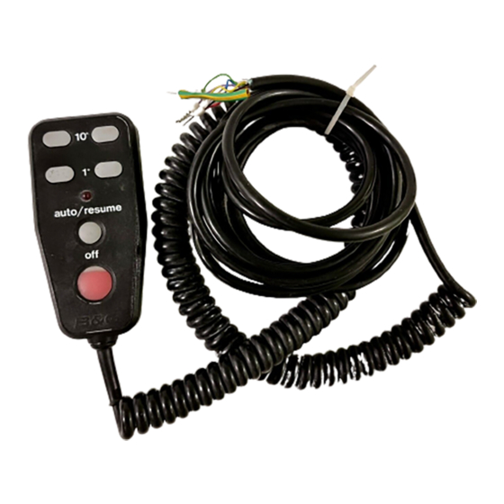
h2000 Autopilot User Manual Part 1 - Introduction (f) Red Off Key (top right of keypad) - This key disengages the Autopilot and returns the boat to Manual Steering. It has no other function. (g) Lights Key (bottom right of keypad) - This key turns the LCD back lighting ON and OFF, and allows three levels of illumination to be selected for all displays (including Instrument System FFDs) under system control. -
Page 11: Joystick
h2000 Autopilot User Manual Part 1 - Introduction (c) Auto/Resume - Autopilot engage and return to course. (d) Off - Autopilot disengage. JOYSTICK 36.0 View from underside dia 21.0 mm 48.0 mm Forward indicator marks 70. 0 mm dia 40.0 mm 45.0 mm 4 holes dia 3.0 mm... -
Page 12: Man Overboard Button
h2000 Autopilot User Manual Part 1 - Introduction (b) Proportional Steering (Prop) - The position of the rudder follows the position of the Joystick. When the Joystick returns to the central position the rudder returns to its initial position. MAN OVERBOARD BUTTON Fig 1.4 - Man Overboard Button The Man Overboard Button (MOB) is an optional extra that activates the Autopilot Man Overboard Alarm Procedure to assist... - Page 13 h2000 Autopilot User Manual Part 2 - Operating Information PART 2 - OPERATING INFORMATION CONTENTS Para Page SWITCHING ON MODE SELECTION 2.2.1 Introduction 2.2.2 Mode Selection STEER TO COMPASS 2.3.1 Introduction 2.3.2 Selecting Compass Mode 2.3.3 Engaging the Autopilot 2.3.4 Dis-engaging the Autopilot 2.3.5 Changing the Autopilot Course...
-
Page 14: Joystick
h2000 Autopilot User Manual Part 2 - Operating Information CONTENTS (Contd.) Para Page POWER STEER 2-18 2.6.1 Introduction 2-18 2.6.2 Selecting Power Steer Mode 2-18 2.6.3 Engaging the Autopilot 2-19 2.6.4 Dis-engaging the Autopilot 2-19 2.6.5 Fine Rudder Adjustments 2-19 2.6.6 Coarse Rudder Changes 2-20... -
Page 15: Switching On
h2000 Autopilot User Manual Part 2 - Operating Information PART 2 - OPERATING INFORMATION SWITCHING ON The h2000 Autopilot has two power supplies (instrument and heavy duty) connected via circuit breakers and/or fuses. The Autopilot Computer and Autopilot Displays are powered via the Fastnet data cable and share the same source of supply as the Hydra, Hercules or HS2000 Instrument System. -
Page 16: Mode Selection
h2000 Autopilot User Manual Part 2 - Operating Information MODE SELECTION 2.2.1 Introduction The Autopilot software automatically determines which modes of operation are available depending on whether the vessel is a powerboat or a sailboat. The Autopilot also receives Waypoint or Wind data via the Fastnet databus from either a compatible position fixer or the Masthead Unit. -
Page 17: Selecting Compass Mode
h2000 Autopilot User Manual Part 2 - Operating Information 2.3.2 Selecting Compass Mode Press the < Key next to the MODE legend until COMPS appears on the top line. 2.3.3 Engaging the Autopilot (1) From the Autopilot Display and with the boat steered on the desired course, press the Key next to the COMPS legend. -
Page 18: Changing The Autopilot Course
h2000 Autopilot User Manual Part 2 - Operating Information 2.3.5 Changing the Autopilot Course Note The Autopilot can be immediately disengaged and the steering returned to manual control by pressing the Red Off Key on any Autopilot Display or Hand-held Controller. (1) Fine Adjustments - Multiple key operations are added together to give the required course change, e.g. -
Page 19: Pre-Setting The Autopilot Course
h2000 Autopilot User Manual Part 2 - Operating Information (3) Temporary Changes (Dodging) - At any Autopilot display press the > Key next to the 10 legend to change the Autopilot course to starboard by 10 . When the key is pressed, the last course is stored in the Autopilot Computer course memory. -
Page 20: Steer To Wind Introduction
h2000 Autopilot User Manual Part 2 - Operating Information (2) Press the < Key (Decrease) and > Key (Increase) next to the < < > > legend to alter the Autopilot legend to pre-set the Autopilot course, displayed on the lower digits. -
Page 21: Selecting Wind Mode
h2000 Autopilot User Manual Part 2 - Operating Information 2.4.3 Selecting Wind Mode (1) At the Autopilot Display press the key next to the MODE legend until WIND appears on the top line. The Apparent Wind Angle (AWA) displayed on the bottom digits is the same as the displayed APP W/A on the Instrument System. -
Page 22: Dis-Engaging The Autopilot
h2000 Autopilot User Manual Part 2 - Operating Information 2.4.5 Dis-engaging the Autopilot (1) At any Autopilot Display press the Red Off Key. The Autopilot disengages and returns to manual steering. (2) At the Hand-held Controller press the Red Off Key. The Autopilot disengages and returns to manual steering. - Page 23 h2000 Autopilot User Manual Part 2 - Operating Information Multiple key operations are added together to give the required wind angle change, e.g. for a 5 ‘target’ wind angle change press the 1 button 5 times. (b) Coarse Adjustments - At any Autopilot Display press the <...
-
Page 24: Auto Tack
h2000 Autopilot User Manual Part 2 - Operating Information (2) Press the < > Keys next to the <<>> legend to alter the wind angle displayed on the lower digits. (3) Press the key next to the WIND legend to engage the Autopilot on the User Defined Wind Angle. -
Page 25: Auto Gybe
h2000 Autopilot User Manual Part 2 - Operating Information 2.4.9 Auto Gybe The Autopilot is also able to indicate when it is possible to execute a Autopilot controlled gybe. When the Gybe Key is pressed the boat will be steered on to exactly the same Target AWA, but on the opposite tack. -
Page 26: Steer To Waypoint Introduction
h2000 Autopilot User Manual Part 2 - Operating Information (2) The appropriate NMEA sentences are selected and set to be transmitted. The minimum data requirement is XTE (cross track error); however, XTE and Bearing to Waypoint give the best steering performance. For Autopilot operation select any of the following: RMB (best option), XTE, APA, or APB together with BWR or BWC. -
Page 27: Selecting The Waypoint Mode
h2000 Autopilot User Manual Part 2 - Operating Information USER TIP Position fixer errors can cause steering inaccuracy. Always maintain a log and position plot on an up-to-date chart. Also, remember to check that the Autopilot course (Waypoint to Waypoint) will steer the boat clear of any obstacles, taking into account the effects of tide. -
Page 28: Dis-Engaging The Autopilot
h2000 Autopilot User Manual Part 2 - Operating Information 2.5.4 Dis-engaging the Autopilot (1) At the Autopilot Display press the Red Off Key. The Autopilot immediately disengages and returns to manual steering. (2) At the Hand-held Controller press the Red Off Key. The Autopilot immediately disengages and returns to manual steering. -
Page 29: Returning To Original Course
h2000 Autopilot User Manual Part 2 - Operating Information 2.5.6 Returning to Original Course (1) At the Autopilot Display, press the key next to the LAST legend to resume the last course. (2) At the Hand-held Controller press the Auto/Resume Key to return to the original course. -
Page 30: Power Steer
h2000 Autopilot User Manual Part 2 - Operating Information USER TIP Allow a time margin for the next Waypoint bearing to stabilise before pressing the next key. Note The Bearing to Waypoint must be supplied via the NMEA interface for this function to operate; i.e. use one of the following NMEA sentences: APB, BWC, BWR, and RMB. -
Page 31: Engaging The Autopilot
h2000 Autopilot User Manual Part 2 - Operating Information 2.6.3 Engaging the Autopilot Note The rudder should be in the amidships position (or the position at which the boat steers a straight course) before the Power Key is pressed. (1) At any Autopilot Display, press the key next to the POWER legend to engage the Autopilot. -
Page 32: Coarse Rudder Changes
h2000 Autopilot User Manual Part 2 - Operating Information USER TIP Multiple operations of the keys are added together to give the required rudder change. 2.6.6 Coarse Rudder Changes (1) At the Autopilot Display press the < > Keys next to the <<... -
Page 33: Engaging The Autopilot
h2000 Autopilot User Manual Part 2 - Operating Information There are two joystick steering options available to the helmsman: (a) Normal Steering (Norm) - The rudder moves in the direction of the joystick. When the joystick returns to the central position the rudder movement stops. The greater the movement of the joystick, the faster the response of the rudder. -
Page 34: Dis-Engaging The Autopilot
h2000 Autopilot User Manual Part 2 - Operating Information 2.7.3 Dis-engaging the Autopilot (1) To dis-engage the Autopilot when in Joystick mode press the Joystick Button and the boat will return to manual steering. (2) At the Autopilot Display press the Red Off Key. The Autopilot disengages and returns to manual steering. -
Page 35: Set-Up Options
h2000 Autopilot User Manual Part 2 - Operating Information SET-UP OPTIONS The Hydra and Hercules Autopilots have eleven common set-up options, however if a Halcyon Gyro Stabilised Compass and its associated processor are installed into the Autopilot system, additional set-up options become available. All set-up options are used to change and select the operating modes, steering characteristics and alarms of the Autopilot System, whether it is fitted to a powerboat or a sailing boat. -
Page 36: Manual Response Set-Up (Resp)
h2000 Autopilot User Manual Part 2 - Operating Information 2.8.1 Manual Response Set-Up (RESP) The RESP set-up controls the response of the steering. Different selections are available dependent on whether the heading source is from the Halcyon 2000 Compass or a B&G Halcyon Gyro compass. -
Page 37: Mode Set-Up (Mode)
h2000 Autopilot User Manual Part 2 - Operating Information To set-up RESP: (1) Press the key shown until RESP is displayed. (2) Press the key shown to scroll through the list of RESP options. NORM ECON PERF 1 PERF 2 PERF 3 PERF 4 (3) When the required response is displayed press the... -
Page 38: Automatic Response Set-Up (Aresp)
h2000 Autopilot User Manual Part 2 - Operating Information To set-up MODE: (1) Press the key shown until desired MODE is displayed. (2) Press the key shown to scroll through the list of MODE options. (2) When the required mode is displayed press the key next to the ENTER legend. - Page 39 h2000 Autopilot User Manual Part 2 - Operating Information (c) NORM – Normal: in this mode, the Autopilot will respond to moderate changes in environmental state before altering its response rate. (d) SPORT – in this mode, the Autopilot will be most sensitive to changing conditions and will automatically increase its response rate to counter environmental changes.
-
Page 40: Recovery Mode Sensitivity (Recov)
h2000 Autopilot User Manual Part 2 - Operating Information 2.8.4 Recovery Mode Sensitivity (RECOV) This function is only available when a Halcyon Gyro Stabilised Compass is connected to the system. Recovery Mode allows the user to select the sensitivity that allows the Autopilot to react to unexpected events, for example sudden wave or wind shifts. -
Page 41: Speed Set-Up (Speed)
h2000 Autopilot User Manual Part 2 - Operating Information 2.8.5 Speed Set-Up (SPEED) The SPEED set-up allows the source used for speed data to be selected. There are three options available: (a) B SPD - Boat speed from a speed sensor (default). (b) SOG - Speed Over Ground from NMEA device. -
Page 42: Autopilot Display
h2000 Autopilot User Manual Part 2 - Operating Information (3) When B SPD or SOG are selected, press the key next to the ENTER legend. Continue with set-up or press the key next to the EXIT legend to return to the normal Autopilot display. -
Page 43: Compass Damping Set-Up (C Dmp)
h2000 Autopilot User Manual Part 2 - Operating Information (2) Press the key shown to select the display function of the bar display when the Autopilot is engaged. (3) When the required display function is displayed press the key next to the ENTER legend. Continue with set-up or press the key next to the EXIT legend to return to the normal Autopilot display. -
Page 44: Nmea Source Set-Up (N Src)
h2000 Autopilot User Manual Part 2 - Operating Information (2) Use the keys shown to adjust the value within the range 0 to 99 seconds. (3) When the required value is displayed press the key next to the ENTER legend. Continue with set-up or press the key next to the EXIT legend to return to the normal Autopilot display. - Page 45 h2000 Autopilot User Manual Part 2 - Operating Information Note When more than one of the same type of NMEA position fixer is connected, i.e. two GPS receivers, then the number following the device identifier, e.g. GP 96, determines which GPS is supplying the NMEA data.
-
Page 46: Course Alarm Set-Up (Crs A)
h2000 Autopilot User Manual Part 2 - Operating Information 2.8.9 Course Alarm Set-Up (CRS A) The CRS A set-up enables the Course Alarm facility. The Autopilot will sound an alarm (if an audible alarm is fitted to the instrument system) and all the system displays flash a warning when the Autopilot off course error is greater than the value set. -
Page 47: Watch Alarm Set-Up (Watch)
h2000 Autopilot User Manual Part 2 - Operating Information 2.8.10 Watch Alarm Set-Up (WATCH) The WATCH set-up enables the watch alarm facility. The Autopilot will sound an alarm (if an audible alarm is fitted to the Instrument System) and cause all the system displays to flash a warning at a pre-set time interval to keep the helmsman and crew alert. -
Page 48: Back Lighting Set-Up (Light)
h2000 Autopilot User Manual Part 2 - Operating Information 2.8.11 Back Lighting Set-Up (LIGHT) The LIGHT set-up alters the LCD backlighting colour for all Autopilot Displays and FFDs connected to the system. There are two selections: (a) RED (default). (b) GREEN. To set-up LIGHT: (1) Press the key shown until LIGHT is displayed. -
Page 49: Joystick Set-Up (Jystk)
h2000 Autopilot User Manual Part 2 - Operating Information 2.8.12 Joystick Set-Up (JYSTK) The JYSTK set-up selects the joystick steering, see the joystick section of this manual for details about the different steering modes. There are two selections: (a) NORM - Normal steering mode (default). (b) PROP - Proportional steering mode. -
Page 50: Autopilot Information On Ffd
h2000 Autopilot User Manual Part 2 - Operating Information AUTOPILOT INFORMATION ON FFD The Hydra or Hercules Instrument System FFD (full function display) can be configured to display a limited range of Autopilot information. This information is accessed via the Autopilot Menu that only appears when a Autopilot is connected. -
Page 51: Man Overboard Facility
h2000 Autopilot User Manual Part 2 - Operating Information 2.10 MAN OVERBOARD FACILITY The Man Overboard Button (MOB) is an optional extra that activates the Autopilot's Man Overboard alarm procedure. The MOB can be used whether the Autopilot is engaged or disengaged. -
Page 52: Manual Recovery (All Boats)
h2000 Autopilot User Manual Part 2 - Operating Information 2.10.2 Manual Recovery (All Boats) (1) Press the MOB as soon as the person is lost overboard. The alarm will sound (if fitted) and the display will show the Man Overboard message. The Autopilot display and the FFDs will now show the bearing and distance to the person overboard. - Page 53 h2000 Autopilot User Manual Part 2 - Operating Information (3) Maintain a lookout and keep visual contact with the person in the water. Reduce the boat speed to LESS THAN 8 knots. Ensure that the area is clear of other boats and obstacles.
- Page 54 h2000 Autopilot User Manual Part 2 - Operating Information Intentionally Left Blank HB-0842-04 2-42...
- Page 55 h2000 Autopilot User Manual Part 3 - Commissioning and Calibration PART 3 - COMMISSIONING AND CALIBRATION CONTENTS Para Page INTRODUCTION TO PILOT COMMISSIONING 3.1.1 h2000 Autopilot Commissioning 3.1.2 Autopilot Installation Check List 3.1.3 Parameters to be Set COMMISSIONING MODE SELECTION 3.2.1 Entering Commissioning Mode COMMISSIONING/CALIBRATION ALONGSIDE...
- Page 56 h2000 Autopilot User Manual Part 3 - Commissioning and Calibration CONTENTS (Contd.) Para Page 3.4.16 Setting the Boat Lag Value 3-24 ILLUSTRATIONS Fig No Page Magnetic DIP Angle Corrections 3-11 Boat Lag Response 3-23 TABLES Table No Page Compass Data Rudder Gain Value 3-22 Boat Lag Value Table...
-
Page 57: Introduction To Pilot Commissioning
h2000 Autopilot User Manual Part 3 - Commissioning and Calibration PART 3 - COMMISSIONING AND CALIBRATION INTRODUCTION TO AUTOPILOT COMMISSIONING 3.1.1 h2000 Autopilot Commissioning Before the h2000 Autopilot can be used, it is necessary to carry out commissioning tests. This encompasses the setting and calibration of various parameters, installation and functional checks of the autopilot System equipment. - Page 58 h2000 Autopilot User Manual Part 3 - Commissioning and Calibration Ram free to move side to side and up and down. Reservoir at highest point if ram split. For Size Three Rams only: The reservoir has been fixed to a bulkhead above the ram and pump.
- Page 59 h2000 Autopilot User Manual Part 3 - Commissioning and Calibration Linkage has not been over extended. No slack or backlash in the linkage. Linkage does not foul when rudder moved hard over to hard over. Arm moves through at least 90° when rudder moved hard over to hard over (there must be at least a 1.0V difference between the end stops).
-
Page 60: Parameters To Be Set
h2000 Autopilot User Manual Part 3 - Commissioning and Calibration 3.1.3 Parameters to be Set The following is a list of the parameters that have to be set during commissioning. They are selected by pressing the keys indicated on the diagrams while in commissioning mode. Each parameter is explained in the following sections: B TYPE Select boat type: Sail, Power P, Power D SWING... -
Page 61: Commissioning Mode Selection
h2000 Autopilot User Manual Part 3 - Commissioning and Calibration COMMISSIONING MODE SELECTION 3.2.1 Entering Commissioning Mode Notes The autopilot must be in STANDBY to carry out this operation. If it is the first time the autopilot has been commissioned, SELCT will be displayed instead of SAIL, PWR P or PWR D. -
Page 62: Commissioning/Calibration Alongside
h2000 Autopilot User Manual Part 3 - Commissioning and Calibration COMMISSIONING/CALIBRATION ALONGSIDE The following parameters should be set before a sea trial: B TYPE Select boat type: Sail, Power P, Power D H SRC Heading Source, compass data selection H OFF Heading Offset, compass alignment correction Magnetic DIP Angle compensation DRIVE Rudder drive type selection... -
Page 63: Heading Source (Compass) H Src
h2000 Autopilot User Manual Part 3 - Commissioning and Calibration 3.3.3 Heading Source (Compass) H SRC The Heading Source setting defines the source for compass data. This setting is determined by the type of heading sensor connected to the system. Most systems will use the Halcyon 2000 compass unit. -
Page 64: Heading Offset (Compass Alignment) H Off
h2000 Autopilot User Manual Part 3 - Commissioning and Calibration 3.3.5 Heading Offset (Compass Alignment) H OFF The Compass Alignment electronically compensates for the misalignment between the autopilot’s fluxgate compass and the Earth’s magnetic field. The boat’s actual heading must be known; use a calibrated bowl compass or hand-held compass for reference. -
Page 65: Rudder Drive Type (Drive)
h2000 Autopilot User Manual Part 3 - Commissioning and Calibration Press Enter to store the value. Fig 3.1 Magnetic DIP Angle Corrections 3.3.9 Rudder Drive Type (Drive) Note Depending upon the type of rudder drive unit fitted, the autopilot controls the rudder drive motor in different ways; this optimises the autopilot steering response. -
Page 66: Setting The Rudder End Stops
h2000 Autopilot User Manual Part 3 - Commissioning and Calibration 3.3.11 Setting the Rudder End Stops Before the autopilot can be used, the position of the rudder end stops must be entered. Notes If the boat is equipped with hydraulically power assisted steering, the engines must be running whilst setting the end stops. - Page 67 h2000 Autopilot User Manual Part 3 - Commissioning and Calibration RUD S - Setting the Starboard End Stop Select RUD S from the menu. Turn the wheel until the rudder is hard over to Starboard. Change the OFF legend to ON using the adjacent keys.
- Page 68 h2000 Autopilot User Manual Part 3 - Commissioning and Calibration RUD T - Rudder Hard-Over Time To finish the rudder end stop commissioning procedure the autopilot must calculate the rudder hardover Port to hardover Starboard time. The following points must be observed before carrying out the procedure: If the boat is equipped with hydraulic power assisted steering, the engines must be running during the...
-
Page 69: Setting The Boat Length (B Len)
h2000 Autopilot User Manual Part 3 - Commissioning and Calibration 3.3.12 Setting the Boat Length (B LEN) The boat’s waterline length in Metres must be entered into the autopilot for it to steer accurately. Select B LEN from the menu. Enter the correct waterline length in metres. -
Page 70: Verify Rudder Power Drive
h2000 Autopilot User Manual Part 3 - Commissioning and Calibration The commissioning sea trial should be carried out under power in open water on a calm day. The procedures for the remainder of the commissioning involve continual course and speed changes, it is therefore important that a constant look out is maintained. -
Page 71: Selecting Power Steer Mode
h2000 Autopilot User Manual Part 3 - Commissioning and Calibration This facility could be used in an emergency if the normal manual steering system became defective, e.g. a broken steering quadrant cable or control rod. It can also assist with diagnosis of faults in the ram drive unit, drive pump or the rudder reference unit and its linkage to the steering system since the autopilot normal course control software is by-passed. -
Page 72: Calibrating The Autopilot Compass
h2000 Autopilot User Manual Part 3 - Commissioning and Calibration Use the << >> Keys to move the rudder, check that the autopilot can move the rudder by large amounts, verify by watching the rudder angle on the display, each press should give approximately 3 rudder movement. -
Page 73: Setting The Heading Offset Value (H Off)
h2000 Autopilot User Manual Part 3 - Commissioning and Calibration With the speed below 5 knots, turn the boat through 360 up to a maximum of 720 at a rate of turn not greater than 2 per second. The display will show the amount of turn completed so far in degrees. -
Page 74: Setting The Speed Calibration Value
h2000 Autopilot User Manual Part 3 - Commissioning and Calibration All B&G paddle wheel type speed sensors are compatible. The Hertz/Knot value is entered into the system to ensure the autopilot steering response is controlled with reference to boat speed. The default Hertz/Knot value is 3.80;... -
Page 75: Checking Rudder Gain Learning
h2000 Autopilot User Manual Part 3 - Commissioning and Calibration 3.4.11 Checking Rudder Gain Learning Steer the boat onto a suitable heading, allow time for the boat to settle on this course. Engage the autopilot in COMPS (compass) mode. AT A SPEED NOT EXCEEDING 15 KNOTS, make at least 6 large course changes of at least 100 (ideally 170 ) by multiple presses of the 10 course... -
Page 76: Setting The Rudder Gain Value
h2000 Autopilot User Manual Part 3 - Commissioning and Calibration Observe the performance of the autopilot when changing course. The rudder gain value is inversely proportional, therefore, if the rate of turn is too SLOW, REDUCE the value of rudder gain and the autopilot will use more rudder. -
Page 77: Boat Lag Value
h2000 Autopilot User Manual Part 3 - Commissioning and Calibration 3.4.14 Boat Lag Value Boat Lag is the time taken for the boat to respond to changes in helm. For example, heavy displacement hulls require a larger value for boat lag. 3.4.15 Checking the Boat Lag Engage the autopilot as previously explained in... - Page 78 h2000 Autopilot User Manual Part 3 - Commissioning and Calibration Boat Type Factory Set Value Typical Values Sail Boats 0.3 to 1.0 Power Boats 0.3 to 1.0 Table 3.3 Boat Lag Value Table Note The factory set value is selected by setting Boat Type and Rudder Drive Type during commissioning.
- Page 79 h2000 Autopilot User Manual Part 4 - Installation Information PART 4 - INSTALLATION INFORMATION CONTENTS Para Page CABLE AND CONNECTION INFORMATION 4.1.1 EMC Compliance 4.1.2 General Wiring Notes 4.1.3 Autopilot Drive Unit Cables 4.1.4 ACP Unit Terminal Details 4.1.5 Clutch Voltage Selection 4.1.6 Dip Switch Location ACP WIRING CONNECTIONS...
-
Page 80: Contents (Contd.)
h2000 Autopilot User Manual Part 4 - Installation Information CONTENTS (Contd.) ILLUSTRATIONS Fig No Page ACP Unit Terminal Details DIP Switch Location Network and Alarm Connections Autopilot Display Connections MOB, Joystick, Hand-held Controller Connections 4-10 Hydraulic Ram Drive Connections 4-11 Continuous Drive Connections 4-12 Direct Speed Input Connections... -
Page 81: Cable And Connection Information
h2000 Autopilot User Manual Part 4 - Installation Information PART 4 - INSTALLATION INFORMATION CABLE AND CONNECTION INFORMATION 4.1.1 EMC Compliance B&G equipment is designed to be operated in leisure craft. Every care has been taken in the design and testing to ensure compliance with the European EMC Directive. -
Page 82: Autopilot Drive Unit Cables
h2000 Autopilot User Manual Part 4 - Installation Information All cables should be routed at least 1m/3ft from cables or components that carry or generate high currents, e.g. alternators, starter motors and cabling, trim-tab cables, etc. To minimise interference avoid routing Network cables alongside high power radio or Radar cables, allow 3m/10ft spacing, or within 1m/3ft of engine starter motors and cables and other cables carrying heavy current. -
Page 83: Acp Unit Terminal Details
h2000 Autopilot User Manual Part 4 - Installation Information 4.1.4 ACP Unit Terminal Details - + - DRIVE DRIVE SUPPLY SUPPLY Fig 4.1 ACP Unit Terminal Details Wire Colour Table Violet Black Yellow Blue Orange Brown White Green Blank Silver N/C Table 4.3 Wire Colour Coding/Abbreviations HB-0842-04... -
Page 84: Clutch Voltage Selection
h2000 Autopilot User Manual Part 4 - Installation Information 4.1.5 Clutch Voltage Selection The ACP Computer Unit can output different clutch/solenoid voltages depending upon the size of the rudder drive unit fitted. The clutch/solenoid valve is only required for rams or rotary drive units. -
Page 85: Dip Switch Location
h2000 Autopilot User Manual Part 4 - Installation Information 4.1.6 Dip Switch Location Fig 4.2 DIP Switch Location HB-0842-04... -
Page 86: Acp Wiring Connections
h2000 Autopilot User Manual Part 4 - Installation Information ACP WIRING CONNECTIONS 4.2.1 Network and Alarm Connections - + - DRIVE DRIVE SUPPLY SUPPLY JUNCTION BOX 288-00-001 Connect like NETWORK CABLE colours together 135-0A-130 (10m/30ft) To the other units connected to the 'FasNet' network ALARM UNIT 130-PK-10... -
Page 87: Autopilot Display Connections
h2000 Autopilot User Manual Part 4 - Installation Information 4.2.2 Autopilot Display Connections Junction Box 288-00-001 Connect like colours together To other units on the Fastnet Network. Network Cable 135-0A-130 (10m/33ft) Note: The extreme ends of the Fastnet Network should be terminated by connecting terminators between the white and green data wires. -
Page 88: Mob, Joystick, Hand-Held Controller Connections
h2000 Autopilot User Manual Part 4 - Installation Information 4.2.3 MOB, Joystick, Hand-held Controller Connections - + - DRIVE DRIVE SUPPLY SUPPLY Joystick and Button Man Overboard 545-00-060 Button (MOB) 302-00-007 Hand-held Controller Fig 4.5 MOB, Joystick, Hand-held Controller Connections HB-0842-04 4-10... -
Page 89: Hydraulic Ram Drive Connections
h2000 Autopilot User Manual Part 4 - Installation Information 4.2.4 Hydraulic Ram Drive Connections DRIVE DRIVE SUPPLY SUPPLY Heavy Duty Power Supply Rudder Reference Unit Circuit Breaker RRF-ACP Solenoid Connector Hydraulic Ram Drive RAM-T0-12V RAM-T1-12V RAM-T2-12V RAM-T2-24V RAM-T3-24V Fig 4.6 Hydraulic Ram Drive Connections HB-0842-04 4-11... -
Page 90: Continuous Drive Connections
h2000 Autopilot User Manual Part 4 - Installation Information 4.2.5 Continuous Drive Connections These are general wiring instructions only, showing the implementation of the ACP outputs to drive a continuous drive pump solenoid valves. The continuous drive pump motor will also require a heavy-duty supply, which is not provided. -
Page 91: Direct Speed Input Connections
h2000 Autopilot User Manual Part 4 - Installation Information 4.2.6 Direct Speed Input Connections DRIVE DRIVE SUPPLY SUPPLY Consult your dealer for the specific speed sensor and housing type suitable for your vessel Fig 4.8 Direct Speed Input Connections HB-0842-04 4-13... -
Page 92: Linear Feedback Connections
h2000 Autopilot User Manual Part 4 - Installation Information 4.2.7 Linear Feedback Connections DRIVE DRIVE SUPPLY SUPPLY Heavy Duty Power Supply Black Circuit Breaker Solenoid Connector Linear Rudder Reference Unit SEN-RUD-LFB Hydraulic Ram Drive RAM-T1-12V, RAM-T2-12V, RAM-T2-24V, RAM-T3-24V Fig 4.9 Linear Feedback Connections HB-0842-04 4-14... -
Page 93: Gyro Stabilised Compass Connections
h2000 Autopilot User Manual Part 4 - Installation Information 4.2.8 Gyro Stabilised Compass Connections - + - DRIVE DRIVE SUPPLY SUPPLY Cut Back Unused Wires + Red 12V Gyro Compass Supply - Blue Gyro Stabilised Compass Sensor Fig 4.10 Gyro Stabilised Compass Connections HB-0842-04 4-15... -
Page 94: Rotary Rudder Reference Sensor (Rrf)
h2000 Autopilot User Manual Part 4 - Installation Information ROTARY RUDDER REFERENCE SENSOR (RRF) 4.3.1 Installation of RRF A number of key points must be considered for optimum performance of the unit: Mount the unit on a flat surface next to the tiller arm or steering quadrant. - Page 95 h2000 Autopilot User Manual Part 4 - Installation Information Fig 4.11 Plan View - Typical System with Tiller Arm and Quadrant The RRF can be mounted in many different positions and orientations depending on the layout of the steering system. Fig 4.12 Steering System Orientation HB-0842-04 4-17...
- Page 96 h2000 Autopilot User Manual Part 4 - Installation Information If the maximum rudder angle is less than 90º then the position of the RRF or the drag-link must be adjusted so that the operating arm of the RRF swings through a minimum of 90º and the output voltage difference is greater than 1 volt from port to starboard lock.
-
Page 97: Linear Feed Back Unit
h2000 Autopilot User Manual Part 4 - Installation Information LINEAR FEED BACK UNIT 4.4.1 Linear Feedback Unit Where installation of the conventional rudder reference unit is difficult or physically impossible, a linear feedback unit (SEN-RUD- LFB) can be used. The linear feedback unit comprises of a tube approximately 23mm (7/8 inch) in diameter and 300mm (12 inch) long. -
Page 98: Rudder Drive Unit
h2000 Autopilot User Manual Part 4 - Installation Information RUDDER DRIVE UNIT 4.5.1 Description A compact dc driven reversible hydraulic pump cylinder assembly for boats without hydraulic steering systems. Five sizes of ram are available giving a wide thrust range to suit all sizes and types of vessel. -
Page 99: Sterndrive Unit Connections
h2000 Autopilot User Manual Part 4 - Installation Information 4.5.2 Sterndrive Unit Connections DRIVE DRIVE SUPPLY SUPPLY Heavy Duty Power Supply (12 v Only) BLACK Rudder Reference Unit Stern Drive Unit (Power Assisted) Fig 4.16 Sterndrive Unit Connections HB-0842-04 4-21... -
Page 100: Rotary Drive Connections
h2000 Autopilot User Manual Part 4 - Installation Information 4.5.3 Rotary Drive Connections DRIVE DRIVE SUPPLY SUPPLY Heavy Duty Power Supply BLACK Rudder Reference Unit Rotary Drive Unit Fig 4.17 Rotary Drive Connections HB-0842-04 4-22... -
Page 101: Proportional Solenoid Connections
h2000 Autopilot User Manual Part 4 - Installation Information 4.5.4 Proportional Solenoid Connections These are general wiring instructions only, showing the connection of the ACP Computer Unit outputs to drive proportional solenoid valves. The continuous drive pump motor will also require a heavy- duty supply;... -
Page 102: Using A Non-B&G Speed Sensor
h2000 Autopilot User Manual Part 4 - Installation Information USING A NON-B&G SPEED SENSOR The speed sensor must have a speed signal output from a Hall- effect device giving positive pulses up to a maximum of 12V. (1) Locate the cable from the speed sensor to the instrument input. - Page 103 h2000 Autopilot User Manual Part 4 - Installation Information Autopilot Computer Cable Unit Boatspeed Function 135-0B-098 Terminals Green Speed Signal Input Red Wire Not Used Not Used Black Ground Blue Wire Silver Screen Screen Table 4.5 Non-B&G Paddle Connection HB-0842-04 4-25...
- Page 104 h2000 Autopilot User Manual Part 4 - Installation Information HB-0842-04 4-26...
- Page 105 h2000 Autopilot User Manual Part 5 - Options PART 5 - OPTIONS CONTENTS Para Page ADVANCED CONTROL PROCESSOR UNIT RUDDER DRIVE DATA 5.2.1 Ram Drives 5.2.2 Type 0, 1 and 2 Ram Drives 5.2.3 Type 3 Ram Drive 5.2.4 Ram Drive Unit Installation 5-10 5.2.5 Mounting a Ram on a vertical Bulkhead...
-
Page 106: Advanced Control Processor Unit
h2000 Autopilot User Manual Part 5 - Options PART 5 - OPTIONS ADVANCED CONTROL PROCESSOR UNIT The Advanced Control Processor (ACP) Unit contains all the electronics for the autopilot operation and control of the rudder drive options. It is designed to be mounted on a vertical flat, smooth surface. -
Page 107: Rudder Drive Data
h2000 Autopilot User Manual Part 5 - Options RUDDER DRIVE DATA WARNING: Accurate performance of the yacht’s steering system is crucial to the safety of you and your crew. B&G always recommend that an Authorised B&G Dealer performs the installation of autopilot drive units. CAUTION: In line with B&G’s policy of continuous product improvement, drive units are regularly updated. -
Page 108: Ram Drives
h2000 Autopilot User Manual Part 5 - Options 5.2.1 Ram Drives A compact DC driven reversible hydraulic pump and cylinder assembly for boats without hydraulic steering systems. Five sizes of drive are available giving a wide thrust range to suit all sizes and types of vessel. - Page 109 h2000 Autopilot User Manual Part 5 - Options The following tables may be used to determine the correct tiller arm length for a typical steering system with a maximum rudder angle of 70 . RAM T0 Hydraulic Linear Drive Midstroke RAM–T0–12V 429mm (16.9”) ½...
- Page 110 h2000 Autopilot User Manual Part 5 - Options 5.2.2 Type 1 and 2 Ram Drives Dimensions Fig 5.1 Type 1 and 2 Ram Drive Dimensions HB-0842-04...
- Page 111 h2000 Autopilot User Manual Part 5 - Options ‘R’ CLIP ROD END W A S H E R TILLER BOLT R3773 16MM LOCTITE RECOMMENDED 12MM QUADRANT THICKNESS W A S H E R NUT TORQUE - 27NM 20 Ft.Ib Fig 5.2 Type 1 and 2 Rose Joint and Ram Bolt Detail HB-0842-04...
-
Page 112: Type 3 Ram Drive
h2000 Autopilot User Manual Part 5 - Options 5.2.3 Type 3 Ram Drive Fig 5.3 Type 3 Ram Drive Unit Dimensions HB-0842-04... - Page 113 h2000 Autopilot User Manual Part 5 - Options Fig 5.4 Type 3 Ram Bolt Detail HB-0842-04...
-
Page 114: Ram Drive Unit Installation
h2000 Autopilot User Manual Part 5 - Options 5.2.4 Ram Drive Unit Installation General consideration must be given to the steering system and its geometry before starting the installation. Many factors must be contemplated for a practical solution. The information given here is for guidance only, although where a maximum or minimum value is given this must be adhered to. - Page 115 h2000 Autopilot User Manual Part 5 - Options The reservoir tap has been switched to the ON position allowing the oil to flow between the reservoir and the pipe. Note The tap ON position is in alignment with the pipe. Fig 5.5 Typical Ram Drive Unit Layout HB-0842-04 5-11...
- Page 116 h2000 Autopilot User Manual Part 5 - Options Fig 5.6 Ram Mounted Parallel to Vessel’s Centre-line KEY POINTS ON INSTALLATION Ensure that the rudder angle is limited by the rudder stops and not the limit of travel of the ram arm. Failure to do this will damage the unit and invalidate the warranty.
- Page 117 h2000 Autopilot User Manual Part 5 - Options b= tiller arm a=half max rudder angle Fig 5.7 Vertical Bulkhead Installation HB-0842-04 5-13...
-
Page 118: Mounting A Ram On A Vertical Bulkhead
h2000 Autopilot User Manual Part 5 - Options 5.2.5 Mounting a Ram on a Vertical Bulkhead Due to the restricted movement of the ram of +14 , -10 for the Type 0, 1 and 2 and +/- 5 for the Type 3, it is important that the maximum rudder angle is carefully measured and the positioning of the ram, tiller arm length and offset are carefully followed as shown in Figure 5.7. - Page 119 h2000 Autopilot User Manual Part 5 - Options 5.2.7 Hydraulic Drive Pumps The Reversible Hydraulic Drive Pump has a small high speed pump driven by a 12V or 24V dc permanent magnet motor. The pump has autopilot check valves to prevent back driving and a pilot operated reservoir valve to enable the unit to drive balanced or unbalanced cylinders.
-
Page 120: Type 1 And 2 Hydraulic Pump Dimensions
h2000 Autopilot User Manual Part 5 - Options 105mm (4.13) 4 holes 7.0mm (0.28) 80mm (3.15) 240 mm (9.45) 88.9mm 50.8mm (3.5) (2.00) centres centres Fig 5.8 Type 1 and 2 Hydraulic Pump Dimensions Fig 5.9 Type 3 Hydraulic Pump Dimensions HB-0842-04 5-16... - Page 121 h2000 Autopilot User Manual Part 5 - Options 5.2.8 Hydraulic Drive Pump Installation Important Note When dealing with any hydraulic system great care must be taken to ensure that a high degree of cleanliness is observed and no dirt, moisture or foreign objects are allowed to enter the system. Only the recommended fluids must be used.
-
Page 122: Single Station System Example
h2000 Autopilot User Manual Part 5 - Options (12) Check the fluid level in the helm unit reservoir. (13) When the system appears to be fully functional, with the pump running and the helm hard over check for leaks. (14) Secure all hoses and cables to prevent damage. Fig 5.10 Single Station System Example Fig 5.11 Dual Station System Example HB-0842-04... -
Page 123: Dual Station System With Bypass Example
h2000 Autopilot User Manual Part 5 - Options Fig 5.12 Dual Station System with Bypass Example Fig 5.13 Dual Station Pressurised System Example HB-0842-04 5-19... - Page 124 h2000 Autopilot User Manual Part 5 - Options HB-0842-04 5-20...
- Page 125 h2000 Autopilot User Manual Part 6 - Diagnostic Data PART 6 - DIAGNOSTIC DATA CONTENTS Para Page DIAGNOSTIC DATA INTRODUCTION 6.1.1 Error Messages FAULT DIAGNOSIS 6.2.1 Fault 100 - Uncommissioned 6.2.2 Fault 101 - Halcyon Gyro Stabilised Compass 6.2.3 Fault 102 - Rudder Reference 6.2.4 Fault 103 - Rudder Drive 6.2.5...
- Page 126 h2000 Autopilot User Manual Part 6 - Diagnostic Data Intentionally Left Blank HB-0842-04...
-
Page 127: Diagnostic Data Introduction
h2000 Autopilot User Manual Part 6 - Diagnostic Data PART 6 - DIAGNOSTIC DATA DIAGNOSTIC DATA INTRODUCTION The Autopilot Computer is continually monitoring the autopilot and Hydra/Hercules System for correct operation. If an error is detected the Autopilot Display will show an error message. When an error occurs, the system audible alarm will sound. - Page 128 h2000 Autopilot User Manual Part 6 - Diagnostic Data Fault Cause Fault Description The boat is stationary or the No Boat Speed speed sensor has stopped FAULT 104 transmitting data Heading data from Halcyon External Compass 2000 Compass or Gyro Sensor FAULT 105 has stopped Navigational data from position...
- Page 129 h2000 Autopilot User Manual Part 6 - Diagnostic Data No regular messages being received by Autopilot Display from Autopilot Computer via Fastnet databus; i.e. either the NO PILOT Autopilot Display Unit display is not receiving or the autopilot computer is not transmitting Table 6.1 Error Messages HB-0842-04...
-
Page 130: Fault Diagnosis
h2000 Autopilot User Manual Part 6 - Diagnostic Data FAULT DIAGNOSIS 6.2.1 Fault 100 - Uncommissioned Fault Description Rudder not commissioned or memory has been corrupted. Remedy (1) Has rudder ever been successfully commissioned? Yes - go to 4. - go to 2. (2) Set rudder end and mid positions, move helm, does rudder indicator work? Yes - go to 4. -
Page 131: Fault 101 - Halcyon Gyro Stabilised Compass
h2000 Autopilot User Manual Part 6 - Diagnostic Data 6.2.2 Fault 101 – Halcyon Gyro Stabilised Compass Fault Description The signal from the autopilot compass is too big or too small. Remedy (1) Check for magnetic interference near compass position. (2) Check all wiring connections to the compass unit. -
Page 132: Fault 103 - Rudder Drive
h2000 Autopilot User Manual Part 6 - Diagnostic Data With someone moving the helm, the signal should change smoothly. If the signal is incorrect, suspect a faulty rudder reference unit. Note the difference between the signal voltages measured at the two end stops must be at least 1V dc. - Page 133 h2000 Autopilot User Manual Part 6 - Diagnostic Data (2) Check installation, look for any slack or loose fixings in the drive system or the rudder reference as the helm is moved. (3) Move the helm. Does the rudder indicator work, if not, check installation of rudder reference unit as detailed above.
-
Page 134: Fault 104 - No Boat Speed
h2000 Autopilot User Manual Part 6 - Diagnostic Data 6.2.5 Fault 104 - No Boat Speed Fault Description The boat is stationary or the speed sensor is not working. Remedy (1) If boat speed for pilot comes from instrument system, check speed shown on instrument system display. -
Page 135: Fault 108 - Bad Nmea Data
h2000 Autopilot User Manual Part 6 - Diagnostic Data 6.2.8 Fault 108 - Bad NMEA Data Fault Description The value of XTE data being received has suddenly changed by more than 0.3 nautical miles. Remedy (1) Check XTE on display for stability. (2) Check operation of Position Fixer, especially signal and noise levels. -
Page 136: Fault 111 - Current Trip
h2000 Autopilot User Manual Part 6 - Diagnostic Data 6.2.11 Fault 111 - Current Trip Fault Description The current limit circuit for the drive motor (25 Amps ACP1 or 40 Amps ACP2) or the clutch (2 Amps) has tripped. Remedy (1) Check installation and wiring for short circuits. -
Page 137: Fault 113 - Memory Card Changed
h2000 Autopilot User Manual Part 6 - Diagnostic Data 6.2.13 Fault 113 – Memory Card Changed Fault Description The memory card fitted is from another pilot and the rudder end-stops are no longer valid. All other information will remain intact. Remedy (1) A pilot reset is required to reset the characteristics. - Page 138 h2000 Autopilot User Manual Part 6 - Diagnostic Data 6.2.16 Autopilot Display Shows "No Pilot" Fault Description No regular messages being received by autopilot FFD from autopilot computer via instrument system network, i.e. either the display is not receiving or the autopilot computer is not transmitting.
- Page 139 h2000 Autopilot User Manual Part 6 - Diagnostic Data PILOT DOES NOT STEER IN A STRAIGHT LINE Fault Description The autopilot seems unable to steer straight, it continually overcorrects course errors; the wake has an "S" like appearance as the boat first steers several degrees off course to Port followed by several degrees off course to Starboard.
- Page 140 h2000 Autopilot User Manual Part 6 - Diagnostic Data Intentionally Left Blank HB-0842-04 6-16...
Need help?
Do you have a question about the B&G h2000 and is the answer not in the manual?
Questions and answers
Bonjour . Peut on avoir une télécommande sans fil avec un pilote B&G H 2000 (Connexion de la base de la télécommande en NMEA 183) ? Merci d'avance de votre prompte réponse Cordialement Michel ROE