Sign In
Upload
Manuals
Brands
Simrad Manuals
Marine Equipment
B&G h2000
Simrad B&G h2000 Marine Electronics Manuals
Manuals and User Guides for Simrad B&G h2000 Marine Electronics. We have
1
Simrad B&G h2000 Marine Electronics manual available for free PDF download: User Manual
Simrad B&G h2000 User Manual (140 pages)
Brand:
Simrad
| Category:
Marine Equipment
| Size: 2 MB
Table of Contents
Table of Contents
5
System Overview
7
Autopilot Operation
8
Controlling the Autopilot
8
Autopilot Display
9
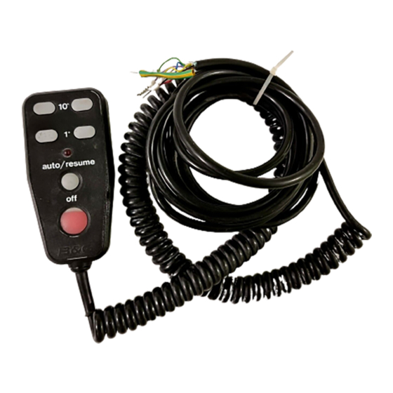
Hand-Held Controller
10
Joystick
11
Man Overboard Button
12
Table of Contents
13
Joystick
14
Switching on
15
Mode Selection
16
Introduction
16
Steer to Compass
16
Selecting Compass Mode
17
Engaging the Autopilot
17
Dis-Engaging the Autopilot
17
Changing the Autopilot Course
18
Pre-Setting the Autopilot Course
19
Pre-Setting the Next Leg
19
Steer to Wind Introduction
20
Selecting Wind Mode
21
Engaging the Autopilot
21
Dis-Engaging the Autopilot
22
Steer to Wind Adjustments
22
Auto Tack
24
Auto Gybe
25
Gybe Zone
25
Using the Gybe Key
25
Steer to Waypoint
25
Steer to Waypoint Introduction
26
Selecting the Waypoint Mode
27
Engaging the Autopilot
27
Dis-Engaging the Autopilot
28
Changing the Autopilot Course
28
Returning to Original Course
29
Waypoint Arrival Next Leg
29
Power Steer
30
Introduction
30
Selecting Power Steer Mode
30
Engaging the Autopilot
31
Dis-Engaging the Autopilot
31
Fine Rudder Adjustments
31
Coarse Rudder Changes
32
MID Key
32
Joystick Steering
32
Introduction to Joystick Steering
32
Engaging the Autopilot
33
Dis-Engaging the Autopilot
34
Normal Steering
34
Proportional Steering
34
Set-Up Options
35
Manual Response Set-Up (RESP)
36
Mode Set-Up (MODE)
37
Automatic Response Set-Up (ARESP)
38
Recovery Mode Sensitivity (RECOV)
40
Speed Set-Up (SPEED)
41
Autopilot Display
42
Off Course Set-Up (Off-C)
42
Compass Damping Set-Up (C DMP)
43
NMEA Source Set-Up (N SRC)
44
Course Alarm Set-Up (CRS A)
46
Watch Alarm Set-Up (WATCH)
47
Back Lighting Set-Up (LIGHT)
48
Joystick Set-Up (JYSTK)
49
Autopilot Information on Ffd
50
Autopilot Course (PLT CRSE M)
50
Rudder Angle (RUDDER )
50
Off Course Error (off CRSE )
50
Man Overboard Facility (man OVER)
50
Autopilot Faults and Errors (PLT ERR)
50
Man Overboard Facility
51
Man Overboard Procedure
51
Manual Recovery (All Boats)
52
Automatic Recovery (Power Only)
52
Table of Contents
55
Autopilot Installation Check List
57
H2000 Autopilot Commissioning
57
Introduction to Pilot Commissioning
57
Parameters to be Set
60
Commissioning Mode Selection
61
Entering Commissioning Mode
61
Boat Type Selection (B TYPE)
62
Commissioning/Calibration Alongside
62
Setting the Boat Type
62
Heading Source (Compass) H SRC
63
Setting the Heading Source Value
63
Adjusting the Heading Offset
64
Heading Offset (Compass Alignment) H off
64
Magnetic DIP Angle DIP
64
Setting the Magnetic DIP Value
64
Magnetic DIP Angle Corrections
65
Rudder Drive Type (Drive)
65
Setting the Drive Type
65
Setting the Rudder End Stops
66
Introduction
69
Sea Trial Commissioning/Calibration
69
Setting the Boat Length (B LEN)
69
Verify Rudder Power Drive
70
Power Steer Check
71
Selecting Power Steer Mode
71
Calibrating the Autopilot Compass
72
Calibration of Speed Input (S CAL)
73
Setting the Heading Offset Value (H Off)
73
Rudder Gain (R GAN)
74
Setting the Speed Calibration Value
74
Checking Rudder Gain Learning
75
Setting the Rudder Gain Manually
75
Setting the Rudder Gain Value
76
Boat Lag Value
77
Checking the Boat Lag
77
Table of Contents
79
CONTENTS (Contd.)
80
Fig no Page
80
Table no Page
80
Cable and Connection Information
81
EMC Compliance
81
General Wiring Notes
81
Autopilot Drive Unit Cables
82
ACP Unit Terminal Details
83
Clutch Voltage Selection
84
Dip Switch Location
85
Acp Wiring Connections
86
Network and Alarm Connections
86
Autopilot Display Connections
87
MOB, Joystick, Hand-Held Controller Connections
88
Hydraulic Ram Drive Connections
89
Continuous Drive Connections
90
Direct Speed Input Connections
91
Linear Feedback Connections
92
Gyro Stabilised Compass Connections
93
Rotary Rudder Reference Sensor (Rrf)
94
Installation of RRF
94
Linear Feed Back Unit
97
Rudder Drive Unit
98
Description
98
Sterndrive Unit Connections
99
Rotary Drive Connections
100
Proportional Solenoid Connections
101
Using a Non-B&G Speed Sensor
102
Table of Contents
105
Advanced Control Processor Unit
106
Rudder Drive Data
107
Ram Drives
108
Type 3 Ram Drive
112
Ram Drive Unit Installation
114
Mounting a Ram on a Vertical Bulkhead
118
Splitting the Ram Drive Unit
118
Type 1 and 2 Hydraulic Pump Dimensions
120
Type 3 Hydraulic Pump Dimensions
120
Dual Station System Example
122
Single Station System Example
122
Dual Station Pressurised System Example
123
Dual Station System with Bypass Example
123
Diagnostic Data Introduction/Fault Diagnosis
125
Diagnostic Data Introduction
127
Error Messages
127
Fault 100 - Uncommissioned
130
Fault Diagnosis
130
Fault 101 - Halcyon Gyro Stabilised Compass
131
Fault 102 - Rudder Reference
131
Fault 103 - Rudder Drive
132
Fault 104 - no Boat Speed
134
Fault 105 - External Compass
134
Fault 106 - no NMEA Data
134
Fault 108 - Bad NMEA Data
135
Fault 109 - no Wind Data
135
Fault 110 - no Optimum Wind
135
Fault 111 - Current Trip
136
Fault 112 - Network
136
Fault 113 - Memory Card Changed
137
Fault 114 - Autopilot Memory
137
Advertisement
Advertisement
Related Products
Simrad BSM-3
Simrad BSM-2
Simrad B&G H1000
Simrad B&G NAC-3
Simrad B&G NAC-2
Simrad B&G RS100
Simrad B&G RS100-B
Simrad B&G V100
Simrad B&G V100-B
Simrad 3383H68
Simrad Categories
Marine Equipment
Transducer
Sonar
Autopilot System
Radio
More Simrad Manuals
Login
Sign In
OR
Sign in with Facebook
Sign in with Google
Upload manual
Upload from disk
Upload from URL