Table of Contents
Advertisement
Advertisement
Table of Contents

Related Manuals for Mikado VBar


Summary of Contents for Mikado VBar
- Page 1 VBar Manual V4.05...
-
Page 2: Table Of Contents
Its applications are diverse. When installing or operating V-Bar, you may have questions which are not answered by this manual. Purchase of this VBar System entitles you to technical support by the manufacturer. If you have any questions or comments, please go to the V-Bar Forum on the following website: www.vstabi.de (Questions... -
Page 3: General Information
The VBar is not an autopilot! An autopilot can steer or hold the heli in a given position. This is not what the VBar does. Rather, the VBar simulates the expected behavior of a conventional rotorhead (which includes a flybar). - Page 4 V-Bar must not lead to any restrictions concerning the safe operation of the model. Of course the VBar cannot be used in any helicopter carrying humans or animals, or in helicopters which could in any manner endanger persons, animals or things.
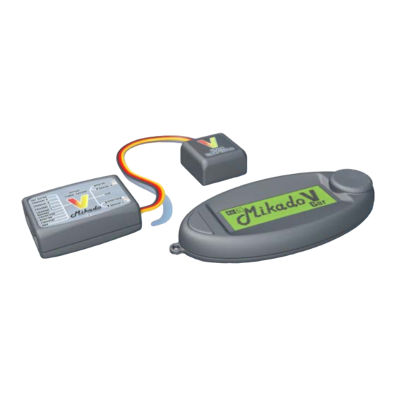
- Page 5 - Central Unit The central unit houses the microprocessor and the power/voltage supply for the V-Bar. The supply voltage is 3.5 to 9 V. The essential criterion for positioning the central unit has to do with wiring. The receiver must be connected without pulling or bending the wires.
- Page 6 VBar kit. - V-Bar power supply (very important) Please note: With 4 digital servos and the VBar, the current consumption of the receiver unit will be at least 50% more than when using a conventional flybar rotor head. You need to adjust power supply for your receiver accordingly.
-
Page 7: How To Program Your Vbar
(Mikado item no. 4056) or the special VBar control panel (Mikado item no. 4145).You can switch among these options at any time, so you can program your VBar at home, at the flying field or anywhere you choose. -
Page 8: Installation Of The Pc Software
There is one exception, namely the 64 bit version of Windows Vista. If you are using Windows Vista 64 bit, or an Apple, MAC or Linux System, please refer to the our VBar support page on www.vstabi.de, where you will find the relevant instructions. - Page 9 On opening the software, you will see a screen as shown below. This is the page for using the pre-installed model set-ups. For the VBar to be able to connect to your PC or Laptop, you need to install a driver.
-
Page 10: Wiring The Vbar To The Receiver
Once your system has installed the USB driver and recognized the VBar you can start up the software in USB mode. The green bar in the upper left corner of the screen indictates successful connection. Transmitter Settings It is sufficient to use a simple 4- channel transmitter with no active mixing. - Page 11 RX1 und RX2. Smaller models need only one satellite, larger models need two. -Satellites made by Fasst and Jeti: These are connected to the plug labelled “AUX“ in the strip of conncetors at the front of the Vbar. VBar with Receiver Satellite Tailrotor Servo...
- Page 12 Mini VBar can be operated with one or two Spektrum satellites. To initiate operation (binding) and for programming, please connect the satellites to the VBar and supply power to the VBar, using a receiver battery. Then conncet the VBar with your PC via the USB cable. On first connection the PC will ask for installation of the drivers.
- Page 13 „prepare binding“ in the set-up menu first. Note: Each time you change the receiver settings, you must confirm these by clicking ENTER, followed by a cold start of the Mini VBar (on/off switch), so that it can initialize again.
-
Page 14: Pre-Defined Set-Ups (Presets)
You may start with this section if and only if you have installed and opened the PC software sucessfully on your computer. Once you have connected the VBar with the receiverv you can begin. - Page 15 After loading a preset into the VBar, the diagram at the bottom of the screen indicates the current assignment of swash plate servos. If your helicopter does not appear among the listed models, select the heli symbol at the very top.
- Page 16 Step 2 Calibration of your Radio Now turn on your radio and the receiver and connect the VBar with your PC. The software will now be in set-up mode for making further adjustments: To ensure correct and troublefree operation of the entire system, the transmitter needs to be calibrated.
- Page 17 VBar site (www.vstabi.de) to obtain the appropriate setting. In your VBar software, you can adjust the servo direction and the limits for both directions. With no stick input, the tail servo is in neutral position in setup mode. This helps to mount the servo arm at the best angle possible.
- Page 18 The following text shows you how. a) Piro Optimization As you may know, one great advantage of the VBar is its integrated tail gyro. This makes it a 3-axis system, which is able to compute simultaneously the movements of the heli and the pilot’s inputs. It is this feature which allows for automatic piro optimization.
- Page 19 Torque compensation for the tail One great advantage of the VBar is its integrated tail gyro. This makes it a 3-axis system, which is able to compute simultaneously the movements of the heli and the pilot’s inputs. It is this feature which allows for automatic torque compensation.
- Page 20 After the direction of collective pitch has been set correctly, the directions of elevator and aileron should also be correct. If this is not the case, please re-check the servo assignments on your VBar. Now fine-adjust the servo arms to an exact 90-degree angle using the control buttons in Step 5 on your screen.
- Page 21 Step 5: Adjust the Swashplate To achieve a geometrically correct mechanical setup of the swash plate with perfectly aligned servo arms, it is necessary to adjust the push rods. The swash plate needs to be centered and level within the pitch travel range.
-
Page 22: Mounting The Sensor
To set the desired maximum for collective pitch, click „Back“ and return to the menu for the flight parameters. There, move the bar for collective until you read the desired maximum collective pitch. Bear in mind that the actual maximum value can only be checked by returning to the Setup mode, so you may have to switch back and forth between the two menus several times. -
Page 23: Checking Travel Directions
Connect the sensor wire to the VBar unit. As shown on the label, the yellow wire faces toward the outside. To avoid the sensor picking up any vibrations from lose wires, secure the wires at approx. 2 cm from the sensor using a cable strap. -
Page 24: Trim Flight
IC powered helis. Autotrim is activated in your VBar software by checking the appropriate box. At the flight line, turn on your heli with the collective stick at full positive. Use throttle hold to prevent the motor from starting, until you are ready to fly. - Page 25 After landing and turning off the motor, move your collective stick to negative to prevent the VBar from continuing it’s trim measurements. The Autotrim flight can now be evaluated using the VBar software. If the bar for Time has risen to a two-third level, uncheck the box to avoid further unwanted changes.
-
Page 26: Tail Settings
Adjust the tail gyro gain using the Gyro Gain bar. It is possible to set Gain to a maximum, but it should not be so high that the tail starts wagging. But with VBar, a much lower value can translate into an excellent tail performance. -
Page 27: Optimization
To activate bank switching, choose Bank Selection Bank 0/1/2/3 in the VBar sofware. Please do not forget to copy your current set-up to all the other banks so you have a basic setup on all of them. The status bar „AUX“ in the „live display“ shows the currently active bank. -
Page 28: Important Safety Guidelines
- Settings The VBar is a system placed between the receiver and the controlling units of the helicopter. Thus the VBar is one of the actively controlling elements of the helicopter. - Page 29 If any parameter is set incorrectly, it is possible that this setting can no longer be overridden via a radio signal. This may lead to an incontrollable crash of the helicopter. Even when overriding is possible, it is usually the case that the pilot cannot react fast enough to make the appropriate correction.
-
Page 30: Rotorhead Set-Up
16. Rotorhead Set-up If you do not want to use a Mikado rotor head in your helicopter, you need to check a few mechanical points in the rotor head, before using the VBar. -
Page 31: Additional Components
V-Bar rotorhead upgrade for LOGO 10/500, item no. 4052 Control Panel for VBar, item no. 4152 Patch cable (servo cable VBar to receiver 80 mm), item no. 4055 Patch cable (servo cable VBar to receiver 100 mm), item no. 4141 Patch cable (servo cable VBar to receiver 150 mm), item no. -
Page 32: Technical Data
Supply Voltage...........3,5-9 V (1) Current Consumption.........max. 150mA Operating temperature .......-15° to 60° Celsius Processors..........2*DSP 32/60 Mhz (1) Absolute Limit. Exceeding these values may cause damage. Mikado Modellhubschrauber , Friedrich-Klausing-Str. 2, 14469 Potsdam Telefon 0331 237490, FAX 0331 2374911, email info@mikado-heli.de... - Page 33 This saves you time and cost. If you do need to send in the VBar for check-up or repair, please send both the main unit and the gyro. Please include a phone number and/ or email address, so we may contact you.
- Page 34 Power supply for receiver? (BEC/Regulator brand and type)....................... Receiver battery NiCd / Lipo / capacity............................Motor and Speed Controler ................................Gyro sensor mounting (soft or hard, how many pads?)........................Damage report Which unit is defect? -Mainboard ..............O..-Gyro Sensor............O..
Need help?
Do you have a question about the VBar and is the answer not in the manual?
Questions and answers