Table of Contents
Advertisement
Advertisement
Table of Contents

Subscribe to Our Youtube Channel
Related Manuals for SyxthSense SYX66 Series


Summary of Contents for SyxthSense SYX66 Series
- Page 1 SYX66x Commissioning Guide V1.10.3 300117 Page 1 of 61...
-
Page 2: Table Of Contents
Table of Contents INTRODUCTION............................... 4 Important Information Regarding Product Safety ..................5 Notes on Disposal ............................5 INPUTS ................................6 ANALOGUE OUTPUTS ............................. 7 OUTPUTS ................................. 7 WEB BROWSER CONNECTION ........................8 CONFIGURATION OVERVIEW ..........................9 Equipment Selection and location ........................10 3.1 Heating Application Example .......................... - Page 3 Commissioning Mode ........................... 32 Factory Defaults ............................32 Overrides Menu Pages ............................33 Switch Page ..............................33 Values Page ..............................34 Times Tab ..............................35 Heating Menu Pages ............................36 10.1 Switch Page ..............................36 10.2 Values Page ..............................40 10.3 Time Page ..............................
-
Page 4: Introduction
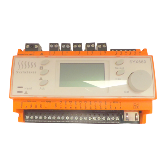
Note to Reader: This manual is to be used as an aid to assist in the commissioning of the SYX660, SYX661, SYX662, SYX663 and SYX664 Controllers from SyxthSense. The SYX66x range of controllers have identical functionality apart from the sensor types they work with. For the purposes of efficiency this one guide reflect all the above controller types and to help reduce repetition the controller is hereon referred to as SYX66x. -
Page 5: Important Information Regarding Product Safety
1.1 Important Information Regarding Product Safety Safety Instructions This document contains information on installing and commissioning the product "SYX66x". Each person who carries out work on this product must have read and understood this document. If you have any questions that are not resolved by this document, you can obtain further information from the supplier. -
Page 6: Inputs
1.3 INPUTS Six temperature sensor inputs and two digital Inputs are available and are to be used as follows. The sensor characteristic type to be used is dictated by the controller part number: Terminal Function Details • Outside economy 13&15 Pin 1 Outside Air Temperature •... -
Page 7: Analogue Outputs
Can also be used to drive a twin pump set via Optimiser Mode Plant the PMPCO Auto change over module from Start/Stop SyxthSense • Also used as the Optimiser Plant Start/Stop signal when Optimiser Only mode selected VT Valve Open •... -
Page 8: Web Browser Connection
Users must ensure that their chosen device is configured to be on the same network range to ensure that a connection can be made. For more information please see the Laptop Fixed IP config video on SyxthSense Video Resource Library http://www.syxthsense.com/video_resources... -
Page 9: Configuration Overview
2 CONFIGURATION OVERVIEW The SYX66x controller is configured by the installer to provide control of simple heating plant. The SYX66x is configured in specific phases. The phases are: Overrides, Heating, Hot Water, Boilers and Connections. The heating and hot water functions are independent of each other but may share some features such as the Boilers and Overrides. These options allow the controller to be easily adapted to best suit particular plant and building applications. -
Page 10: Equipment Selection And Location
3 Equipment Selection and location 3.1 Heating Application Example Room 1 Pump Valve Room 2 Boiler Boiler System Side Load Side Room 3 Exterior Wall Outside Air Sensor located on North Facing wall shaded from direct sunlight Boiler Flow Sensor located in common flow pipe from boilers. Return Sensor located in main return pipe to boilers on system side. - Page 11 3.2 HWS Application Example HWS Storage Calorifier Boiler Boiler Valve HWS Circ The HWS Control Circuit is enabled from an IO-1RM relay connected on 30&35 (Pin 8). This output may also be used to provide a control signal to the HWS Circulation Pump enable circuit (by others).
-
Page 12: Connection Diagrams
4 Connection Diagrams 4.1 Connection Diagram: Optimiser Mode • One Space Sensor is required for the optimiser to function. The second is optional. • The HWS Control and its options are optional. • The boilers only serve the HWS Function (if linked) in Optimiser Only application •... -
Page 13: Connection Diagram: Optimiser/Compensator Mode
4.2 Connection Diagram: Optimiser/Compensator Mode VT Flow Outside Heating Boiler Temp Return Flow Boiler 1 Boiler 2 Pump Open Close 9 10 11 12 13 14 15 16 17 18 SYX66x 12vDC 0v 27 28 29 30 31 32 33 34 35 36 Space 0-10v Space... -
Page 14: Connection Diagram: Compensated Day/Night Reduced
4.3 Connection Diagram: Compensated Day/Night Reduced VT Flow Outside Heating Boiler Temp Return Flow Boiler 1 Boiler 2 Pump Open Close 9 10 11 12 13 14 15 16 17 18 SYX66x 12vDC 0v 27 28 29 30 31 32 33 34 35 36 Space 0-10v Space... -
Page 15: Connection Diagram: Compensated Day/Night Frost Protection
4.4 Connection Diagram: Compensated Day/Night Frost Protection VT Flow Outside Heating Boiler Temp Return Flow Boiler 1 Boiler 2 Pump Open Close 9 10 11 12 13 14 15 16 17 18 SYX66x 12vDC 0v 27 28 29 30 31 32 33 34 35 36 Space 0-10v Space... -
Page 16: Connection Diagram: Y Plan Mode
4.5 Connection Diagram: Y PLAN Mode • One Space Sensor is required for the optimiser to function. The second is optional. • The HWS is enabled from 11 & 12 • The boilers link option must be selected and the Aux input set to HWS Demand •... -
Page 17: Access And Controller Configuration
Access and Controller Configuration To Set-up the controller, the user must be logged into the SYX66x at level 2. To access the Logon Screen on the controller please Press and Hold the ESC button for 5 Seconds. Select User 2 The passcode for Set-up level is 0112 Turn and Press the Wheel to select the above code Once you have 0112 on the Controller press the Select Button to enter it... - Page 18 Once logged into the controller at Level 2 select each menu in turn and configure the Set-Up options as discussed below. Only the Set-up options should be configured at this time, do not worry about the other parameters as these may not be required.
- Page 19 All of the Set-Up Options will now be discussed in turn: Menu Set-Up Option Description Options Enabled (Default) – When the switch is closed Overrides HWS Extend If the time extension input (Pin 9) is closed for heating the HWS will be time enabled in addition to the extend, do you want the heating.
- Page 20 Night Setback – Uses a compensated curve for Heating Heating Select the Mode of control that best Mode suits the occupation pattern and use Day and a reduced heating curve for night of the building periods. Typically used in 24hr occupied facilities. Typically used when replacing older controllers like CSC with time clock.
- Page 21 Flow Flow Economy will turn the heating off Active (Default) Economy during an occupation period if the Inactive Mode space temperature is at or above the Space Set point and the current heating flow set point is within 7 degrees of the Space Set point. Optimiser Allow the optimiser to self-learn or Enable (Default) / Disable...
- Page 22 Independent (Default) – The boilers will not Boiler Link Option You can request the boilers to run when the HWS time run when the time schedule or time override schedule is active (or if there is on is a qualified demand – Boiler Linked –...
- Page 23 Connections 0-10v output The controller offers a 0-10v VT Valve (Default) 0-100% - For direct 0-10v output and you can chose its control of the VT valve. (The Open Close purpose. Signals from the relays are not affected) (Boiler set point can be scaled Boiler Setp (Scalable) (e.g.
-
Page 24: Controller Principles And Operational Features In Detail
6. Controller Principles and Operational Features in detail 6.1 Optimum Start The optimum start facility is a self-learning routine which will search for the latest time to start in order to achieve the desired Space Set point at the start of occupation. The performance of the optimiser is continually monitored throughout the pre-heat period and updated to ensure an accurate response in all conditions. -
Page 25: Flow Economy Mode
2. Boiler Set Point scaled over a 0-10v signal 3. Boiler % Demand 0-100% over 0-10v output this can be used direct to a condensing boiler or boilers or can be sued to drive a step controller such as the BPRO range from SyxthSense. SYX66x Commissioning Guide V1.10.3 300117... -
Page 26: Valve Exercise
An extend period may be cancelled at any time by setting the override status to reset. An external button (latching type like SyxthSense LAP5) connected to pin 9 will directly start a time extend period when the input closes. The controller will show the extension period as active when either the software timer or external button is pressed. -
Page 27: Parameter Summary
7. Parameter Summary Parameter Default Range Description 07:00 – 00:00 – 24:00 Heating Times Periods of occupation. Up to 4 periods per day 16:00 Monday to Friday 06:00 – 00:00 – 24:00 Hot Water Times Time periods for the Hot Water channel. Up to 4 15:00 periods per day. - Page 28 Parameter Default Range Description Heating Override 0 to 10h Time Extension Period in Hours Period HWS Override Period 0 to 10h Time Extension Period in Hours Adaptive – Non-adaptive If selected, the compensator will self- VT Set point Self Adaptive Adaption adapt with Space Influence.
- Page 29 5°C – 50°C Space Night Set point 16°C The space temperature below which night setback mode control operates. (Used only with Night Setback Mode) Building Warm Up 0.5 to 10 Calculated rate of room temperature rise Rate for the building when heating is first °C/Hour turned on Parameter...
- Page 30 Parameter Range Description Default 0°C – 50°C Schedule Difference Used for valve/boiler systems only. This 10°C value is used to determine when the boiler can be switched off. If the boiler temperature is greater than the required compensated flow temperature plus the schedule difference, then the boiler will switch off.
- Page 31 0 – 100 °C 0-10v Boiler Set point Set point Low If the output is used as a boiler set point Scaling then it scaling can be adjusted to suit the 0 – 100 °C Set point High boiler(s) being used 0 –...
-
Page 32: Menu Pages And Methods To Access Them
The controller is shipped with the following IP Address: 192.168.1.99/Subnet Mask 255.255.255.0/Gateway 192.168.1.1. Your laptop must be configured to be on the same IP address range. For more information on this task please see a tutorial on this subject at http://www.syxthsense.com/video_resources. 8.3 Passcodes Hold the ESC key for 5 Seconds to change user level, Press the wheel to select a number, Press Select button when code complete to Enter it. -
Page 33: Overrides Menu
9. Overrides Menu Pages 9.1 Switch Page Panel Switch - This allows the user to fix the mode of the controller – Auto, Summer, Continuous, Frost, Service Extend Active/Waiting Indication – This will be active when a time extension has been requested. If the actual time program is still active then the indicator will flash. -
Page 34: Values Page
Set-up HWS Extension – Enable/Disable – The engineer has the choice to use the Time Extend input (PIN 9) to be used as a time extension timer such as the LAP5 or LAP10. Closing this contact will bring the heating on into a Controlled Day mode condition. -
Page 35: Times Tab
9.3 Times Tab Here you can program the Holidays that will place the Heating into Frost protection and the HWS will be switched off also. SYX66x Commissioning Guide V1.10.3 300117 Page 35 of 61... -
Page 36: Heating Menu
10. Heating Menu Pages 10.1 Switch Page Temperature Control – Space Frost – This will indicate the presence of a space frost condition. The controller as detected a low space temperature and will have initiated the heating system. This will clear when the space sensor has increased by 2’C above the Space Frost Set Point. - Page 37 Pump Required – Indicates the controller’s requirement for the heating pump. This indicator will be Yellow if running only due to an outside frost condition. VT Pump Override – The user can force the pump On or Off if required. The Hand LED will illuminate on the controller facia.
- Page 38 Commission Mode Switch – Off = Normal, On = Forces the outside sensor to 5’C and the room sensor to 18’C. This allows commissioning during the summer period. Note: 0’C will also be displayed for the Outside Air Sensor should it become faulty or become disconnected. The controller will go into a Day Mode should this be the case.
- Page 39 For more information on Optimiser performance and getting the best out of your control system please read. “Optimising your control system” from SyxthSense. It is full of information on how to understand controllers and how to fix issues perceived to be their making.
-
Page 40: Values Page
10.2 Values Page Room High Limit Setpoint – This displays the calculated High Limit Setpoint for the room temperature. If the space temperature goes above this value then the heating will be disabled until it has dropped 1’C below it. Origin –... - Page 41 VT Setpoint – This shows the current target VT Setpoint VT Ratio – this is the shift increase in flow temperature setpoint for each degree below 20’C outside. Typical settings for this depend on the system being used and the available range between the min and max permitted set points: Underfloor Heating Systems: 1.5 Radiators in a school: 3...
- Page 42 Space Set point – The target room set point for the Optimiser and Heating control room influence control. If no room sensor is used/available users can still adjust the room set point if too hot or too cold to make an effect on the heating flow set point.
- Page 43 Outside High Set point – If the outside air sensor goes above this value then the heating circuit will be switched to Outside High Mode. The heating will come back on if the outside air sensor falls more than 1’C below this set point. Outside Frost Set point –...
- Page 44 VT Valve Time (0 to 100%) – Enter the time in seconds that it takes for the VT Valve to move from the fully closed position to the fully open position. This can be timed by using the controller manual Valve Manual override feature and driving the valve to the fully closed position (0%).
-
Page 45: Time Page
10.3 Time Page To access the Heating Time, select the times Tab . You can edit the times by clicking on individual days or by selecting the Week Program Tab. Enter a Special time/Holiday or Period by selecting the Special Times Tab SYX66x Commissioning Guide V1.10.3 300117 Page 45 of 61... -
Page 46: Hws Menu
11. HWS Menu Pages 11.1 Switch page HWS Override – This allows the user to override the HWS System independently of the heating system. The HWS Times can be overridden On or Off. This will be the case until the HWS is set back to Auto. Setting the controller to Auto will allow it to follow the Time Schedule and extension overrides. -
Page 47: Values Page
a VT Valve may need to be installed. Do not permit a high primary flow temperatures into heating areas serving young children or old people unless adequate measures to protect against surface contact is made. This controller is not responsible for the settings left for safe and continued operation. If in doubt ask. The Primary flow set point can be adjusted but this will affect recovery times and also the available tank temperatures. -
Page 48: Time Page
11.3 Time Page Select Times Tab to access the time schedule for the HWS SYX66x Commissioning Guide V1.10.3 300117 Page 48 of 61... -
Page 49: Boilers Menu
12. Boilers Menu Pages 12.1 Switch Page Boiler 1 Lead – The indicator will be green when Boiler 1 is lead (the first boiler to fire) Boiler 2 Lead – The indicator will be green when Boiler 2 is lead (the first boiler to fire) Sequence –... - Page 50 Set-Up - Rotate Boilers – During set up you can decide if you would like to rotate the boilers. If set to disabled then the boilers will not rotate either manually using the Sequence menu option or in Auto. Note: If you have one boiler but this has two stages (e.g. Low/High Fire) then leave the option Disabled and Set Number of Boilers to 2.
-
Page 51: Values Page
12.2 Values Page Schedule Difference – This is the added offset to the boiler set point when the boilers are feeding a VT Valve. This offset is designed to overcome system losses in the distribution thus ensure the heating demand is being met. Boiler Low –... - Page 52 Boiler High – The maximum flow set point that the controller will try to achieve. Note the boiler thermostat/control will need to also be set to allow this. Flow Temp – The current common boiler flow temperature. The boiler controls will not run if this is not connected or working.
-
Page 53: Times Page
12.3 Times Page Chose the Times Page to view the Boiler Rotation Time. The times are not user adjustable. A manual force of rotation is provided in the Switch Menu with the Rotate Now Option. If rotation is not needed then Auto rotation should be disabled. Rotate Now operation is also inhibited if Auto rotation is disabled. -
Page 54: Connections Menu
Always check the input impedance and rating of the signal to the boilers. 0-10v Amplifiers are available from SyxthSense if required. Note: 0-10v Signal is not suitable to drive 1RM 12v Coil relays. -
Page 55: Values Tab
13.2 Values Tab Setup Output – The Current Signal reading irrespective of the signal purpose This relates to Option 2 Boiler Set point and the scaling of the value This controller provides a direct reading of the current boiler set point but scaled over a 0-10v signal. This equates as follows: 0v = 0’C 10v = 100’C... -
Page 56: Alarms And Management
Alarms and Management 14.1 Sensor Alarms All Sensors are monitored for correct connection. Messages will be populated based on the time and date of disconnection. It is essential that wiring of sensors is made when the controller is isolated from a power supply to avoid unwanted alarms. - Page 57 SYX66x Commissioning Guide V1.10.3 300117 Page 57 of 61...
-
Page 58: Maintenance And Warranty
15. Maintenance and Warranty The controller itself requires no maintenance. The controller is covered by a 12 month warranty. 16. Using the colour touchscreen Below is an example image when using the colour touchscreen. Shown are the levels when the panel switch is selected in the overrides menu. - Page 59 A full range of control features are enabled such as holidays, time extensions, 7 day with 4 periods per day time controls on both heating and hot water. Frost protection routines are enabled outside of the heating periods. SUMMER The normal hot water controls are operating as in Auto but the heating controls are set to be in frost mode. Full frost protection of the heating system is in place, safeguarding the building.
-
Page 60: Faq
A. User 0 = 0000, User 1 = 1111, User 2 is 0112, User 3 is for special access purposes only. Q. I want to change the controller IP address, how can this be done? A. Contact SyxthSense and we will provide assistance on this. Q. Does the time clock automatically adjust for Summer/Winter and Leap Years? A. - Page 61 SyxthSense Ltd 3 Topsham Units Dart Business Park Topsham Exeter EX3 0QH United Kingdom Tel: 0844 840 3100 Fax: 0844 840 3200 Email: info@syxthsense.com Internet: www.syxthsense.com SYX66x Commissioning Guide V1.10.3 300117 Page 61 of 61...
Need help?
Do you have a question about the SYX66 Series and is the answer not in the manual?
Questions and answers