Table of Contents
Advertisement
Quick Links
Advertisement
Chapters
Table of Contents

Subscribe to Our Youtube Channel
Related Manuals for Vermes MDS 3200+ Series


Summary of Contents for Vermes MDS 3200+ Series
- Page 2 MDS 3200 MDC 3200 MDV 3200A MDS 3200 MDC 3200 MDV 3200A-AC MDS 3200 -AC-UF MDC 3200 MDV 3200A-AC-UF MDS 3200 MDC 3200 MDV 3200F MDS 3200 F-HS MDC 3200 MDV 3200F-HS VTK-VS-BA-015e-A | User Manual MDS 3200+ Series | Introduction...
-
Page 3: Table Of Contents
Microdispensing Valve MDV ....................26 4.2.1 Composition ........................... 26 4.2.2 Explosion View MDV ......................28 4.2.3 Specification ........................... 28 4.2.4 Valve Types ..........................29 4.2.5 Special Features of the MDV 3200 series ................30 VTK-VS-BA-015e-A | User Manual MDS 3200+ Series | Introduction... - Page 4 Explanations ........................... 59 PLC Interface: 15-pin, Sub-D ....................79 7.2.1 Pin Functions .......................... 79 7.2.2 Remote Adjust ........................80 7.2.2.1 What is the Remote Adjust? ....................80 7.2.2.2 Advantages ..........................80 VTK-VS-BA-015e-A | User Manual MDS 3200+ Series | Introduction...
- Page 5 Dimensional Drawing MDV 3200A ..................119 13.4 (F) Dimensional Drawings MDV 3200F ................. 120 13.5 Connection Diagram PLC-Interface ..................122 13.6 Declaration Concerning Decontamination of Shipped Equipment ........123 Index ..................... 124 VTK-VS-BA-015e-A | User Manual MDS 3200+ Series | Introduction...
-
Page 6: Introduction
INTRODUCTION With a micro dispensing of the MDS 3000 line from Vermes Microdispensing you have bought a high quality product. Due to the long-standing experience of the team in regards to electronic de- vices and piezo controls, these products provide highest functionality and reliability. -
Page 7: General Instructions
An operating procedure which, if not strictly observed, may result in IMPORTANT NOTE! damage to the equipment, unexpected interruptions or shutdown. Supplementary recommendation for an economical and time-saving INFORMATION! use of the equipment. VTK-VS-BA-015e-A | User Manual MDS 3200+ Series | General Instructions... -
Page 8: Illustration Convention
Nozzle Adjustment Nut NAN-fix Nozzle Adjustment Nut with fixation Nozzle Insert Nozzle Unit NU-fix Nozzle Unit with fixation Programmable logic controller Point of Dispensing Realtime Clock Tappet Guidance Tungsten carbide Tappet, Flat VTK-VS-BA-015e-A | User Manual MDS 3200+ Series | General Instructions... -
Page 9: Tools
Intended Purpose: 1. Squeezing out of the tappet sealing between fluid box and actuator (1.) 2. Detaching the nozzle insert from the tappet guidance (2.) VTK-VS-BA-015e-A | User Manual MDS 3200+ Series | General Instructions... -
Page 10: Mdt 310 Tappet Changing Tool
Tighting screw for MDF 3070-CC Page 94 Fluid box connector Luer-Lock Page 94 MNL screw Page 37 Tappet guidance PEEK Page 32 Tappet guidance H Page 32 Tappet centering screw Pages 100 or 103 VTK-VS-BA-015e-A | User Manual MDS 3200+ Series | General Instructions... -
Page 11: Safety Notes
VERMES Microdispensing does not accept any liability for material damages or personal injury orig- inating from inappropriate use, violation of safety prescriptions, or any procedure inconsistent with the instructions of this manual. -
Page 12: Contracted Use
For further questions concerning current applications and modifications of the system with respect to new requirements, contact the manufacturer, the responsible sales partner or the Technical Support. VTK-VS-BA-015e-A | User Manual MDS 3200+ Series | Safety Notes... -
Page 13: Specification And Technical Notes
• To clean the actuator, a cloth not fluffy and lightly moistened (e.g. by Isopropanol) is rec- ommended. During the cleaning procedure, no liquid should penetrate into the actuator itself (e.g. through the plug). VTK-VS-BA-015e-A | User Manual MDS 3200+ Series | Safety Notes... -
Page 14: Qualifications Of Operators And Maintenance Personnel
• An overall and gloves resistant to the corresponding chemical fluid When you work in the direct vicinity of the MDS for a prolonged period, you should also wear ear protection. VTK-VS-BA-015e-A | User Manual MDS 3200+ Series | Safety Notes... -
Page 15: Product Description
1x Mains plug (110/240 V AC) Plug contacts (Back) 1x 9 pin Sub-D RS-232C 1x 15 pin Sub-D PLC 1x Aux-output 24V 1x Sensor socket 1x Actuator socket 1x Socket for heating 1x Thermocouple socket VTK-VS-BA-015e-A | User Manual MDS 3200+ Series | Product Description... -
Page 16: Front Side
Red: The value is too high and must be lowered according to the instructions of this manual, see page 37. Control lamp for status of heating: This red LED indicates the activity of the heating. ON, heating activated, otherwise OFF. VTK-VS-BA-015e-A | User Manual MDS 3200+ Series | Product Description... -
Page 17: Back Side
Different inputs and outputs may be connected. For the communication protocol, refer to page 79. Shackle for the mains cable: Secures the mains cable against slipping off. Mains connector: Connects the control unit to power supply. VTK-VS-BA-015e-A | User Manual MDS 3200+ Series | Product Description... -
Page 18: Function Keys
Direct access to the next-higher menu level. Access to the next-higher menu level..or ... Increasing of a numerical value. Access to the next-lower menu level..or ... Reduction of a numerical value. VTK-VS-BA-015e-A | User Manual MDS 3200+ Series | Product Description... - Page 19 Settings for Scenarios will not be reset back to the factory settings. That is only possible with the options “Scenario” and “Reset ALL” after entering the service code 1000 (s. chapter 4.1.5.7). VTK-VS-BA-015e-A | User Manual MDS 3200+ Series | Product Description...
-
Page 20: Menu Structure
• In the submenu “Scenario” you can enter values for pre-defined scenarios. Here you can also set the option to work with these scenarios. • The submenu “Service-Option” is used to enter service codes and to change the baud rate. VTK-VS-BA-015e-A | User Manual MDS 3200+ Series | Product Description... -
Page 21: Main Menu
In “Tappet” and “Nozzle” you can see the current values as well as the respective reference value. If a heater is used, instead of “Ready” the current temperature is displayed. VTK-VS-BA-015e-A | User Manual MDS 3200+ Series | Product Description... -
Page 22: Submenu "Pulse Parameters
INFORMATION! While heater is turned “OFF”, the MDC will answer with “No Heater” to the serial command “TEMP:?”. VTK-VS-BA-015e-A | User Manual MDS 3200+ Series | Product Description... -
Page 23: Submenu "Status
“MNL Calibration is Missing!” appears. In “Enter MNL” you can enter a MNL value and set it accord- ingly. “MNL Calibration” is used to calibrate the MNL screw of your valve. Open the MNL screw as instructed before an MNL calibration. VTK-VS-BA-015e-A | User Manual MDS 3200+ Series | Product Description... -
Page 24: Submenu "Scenario
“low”. If the trigger signal is already “low” when reaching the signal, only one pulse will be shot. Then the next setup of the scenario will follow after the scenario delay (unless, of course, it was al- ready the last setup of the scenario). VTK-VS-BA-015e-A | User Manual MDS 3200+ Series | Product Description... -
Page 25: Submenu "Service-Option
RS-232C (page 55). The remaining ten EEPROM memory sets can be used to save different parameter setups when programming the controller through the keypad interface (use the command [save]). VTK-VS-BA-015e-A | User Manual MDS 3200+ Series | Product Description... -
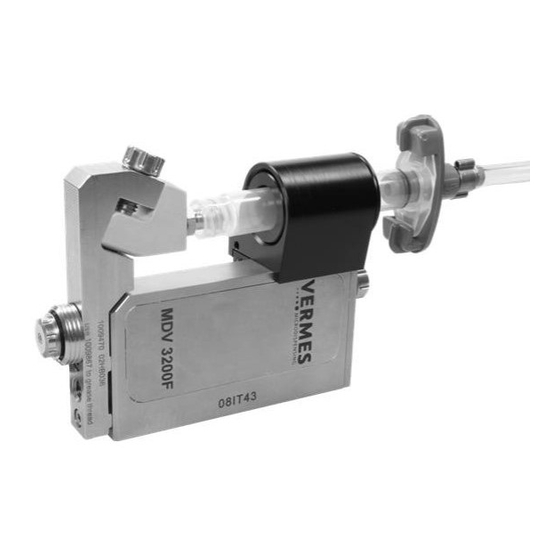
Page 26: Microdispensing Valve Mdv
Microdispensing Valve MDV 4.2.1 Composition The Microdispensing valves of Vermes Microdispensing are built modular. A valve is composed of different modules, four for an A-valve or five for an F-valve (the example picture shows an F-valve): • Electronics/Sensor Electronics (1) •... - Page 27 To turn the MNL screw, you can either use tool MDT 302 or the universal tool MDT 301. Only the MDV 3200F has got an MNL screw. CAUTION! (Open MNL screw) Before each adjust make sure to open the MNL screw completely. VTK-VS-BA-015e-A | User Manual MDS 3200+ Series | Product Description...
-
Page 28: Explosion View Mdv
All aqueous fluids, organic solvents, weak acids and bases Dimensions (Basic Model) 95 mm x 39,5 mm x 23 mm ca. 258 g (depending on configuration) Weight Position of Tappet in Absence of Voltage Open VTK-VS-BA-015e-A | User Manual MDS 3200+ Series | Product Description... -
Page 29: Valve Types
Since F-valves differ from A-valves, those chapters only relevant for F-valves are marked with an “(F)” in the title. Smaller sections are marked with an F-icon (see 2.2.3). VTK-VS-BA-015e-A | User Manual MDS 3200+ Series | Product Description... -
Page 30: Special Features Of The Mdv 3200 Series
Comprehensive Material Selection Only the best materials are used for the production of Vermes Microdispensing valves. • All parts in contact with the transported medium consist of high-alloy special steel, rust- and acid-resisting, or modifications of high-duty polymers of the PE, PEEK and PTFE fami- •... -
Page 31: Initial Operation
INITIAL OPERATION Delivery VERMES systems are shipped in carefully packed state. Transport damages however can never be totally excluded, and deadlines stated in insurance contracts should not be ex- ceeded. 5.1.1 Unpacking For this reason, the merchandise has to be visually inspected immediately after receipt. -
Page 32: First Assembling Of The Mdv
− Slide the cartridge holder onto the side of the MDV, the magnets must face towards the valve. Depending on the size of the cartridge, you might have to add an insert into the cartridge holder (see pictures next page). VTK-VS-BA-015e-A | User Manual MDS 3200+ Series | Initial Operation... -
Page 33: Installation Of The Mds 3200
For high-duty applications (from ca. 300 Hz) or in the case of an air-cooled model (AC vari- ants), a rack with separate ventilation is advisable, since in these situations an airflow of 30 m /h for each MDC 3200 is compulsory. VTK-VS-BA-015e-A | User Manual MDS 3200+ Series | Initial Operation... -
Page 34: Installation Of The Valve As Part Of A Machine
IMPORTANT NOTE! (Connecting cables) Verify during the connecting procedure that the red points on the plugs point towards each other. VTK-VS-BA-015e-A | User Manual MDS 3200+ Series | Initial Operation... -
Page 35: Sensor Cable
Then pull both connectors apart without losing the grip and they will separate. Do not pull at the cables! Grip here! VTK-VS-BA-015e-A | User Manual MDS 3200+ Series | Initial Operation... -
Page 36: Mains Cable
If the valve is not connected, an error message (“VALVE NOT PRESENT“) appears on the screen. Switch OFF the system, disconnect it from the mains and complete the installation before continuing. VTK-VS-BA-015e-A | User Manual MDS 3200+ Series | Initial Operation... -
Page 37: The Adjust Process
The completely open and closed positions of the MNL screw are marked by a slightly higher resistance. This step is only necessary for F-valves, since other valves do not have an MNL screw. Never perform the adjust with a closed MNL screw. VTK-VS-BA-015e-A | User Manual MDS 3200+ Series | Initial Operation... - Page 38 Keep turning till the red adjust LED is ON. The value shown in the display should be about 1100. IMPORTANT NOTE! (Upper Limit) Maximum admissible display value is 1250. Otherwise the tappet could break. VTK-VS-BA-015e-A | User Manual MDS 3200+ Series | Initial Operation...
-
Page 39: F) Mnl Calibration
MNL screw in clockwise. Turn it speedy, but not too much force in, till you reach the end. Use tool MDT 301, since it can be turned in finer steps than MDT 302. VTK-VS-BA-015e-A | User Manual MDS 3200+ Series | Initial Operation... -
Page 40: F) Mnl Adjust
Otherwise you enter the value at the start of the process. With the MNL adjust you can fully use the MNL screw. Therefore it is only important, if you want VTK-VS-BA-015e-A | User Manual MDS 3200+ Series | Initial Operation... - Page 41 Once you have exactly reached the pre-designated value, the display shows “xx µm ok Press Enter“ (“xx“ again represents your chosen value). Press [enter] and the MNL adjust is completed. The display will jump back to the main menu at this point. VTK-VS-BA-015e-A | User Manual MDS 3200+ Series | Initial Operation...
-
Page 42: Initial Liquid Supply
After establishing a convenient dispensing pressure, activate the pneumatic supply. Valves designed by VERMES Microdispensing can be operated at a relatively low supply pressure, in the range between 0 and 7 bar. This upper limit should not be exceeded in nor- mal applications;... -
Page 43: Operation
The maximum value for the “Open Time” is limited to 15 ms, if the “Needle Lift” is set to more than 80 %. If not, the limit is 3000 ms. The length of the “Open Time” de- pends on the PLC-signal (logic 1). VTK-VS-BA-015e-A | User Manual MDS 3200+ Series | Operation... -
Page 44: Parameters For Dispensing Process
The elevated temperature in this range reduces the average frequency and the lifetime of the valve. A needle lift between 70 % and 80 % is the best working range. VTK-VS-BA-015e-A | User Manual MDS 3200+ Series | Operation... -
Page 45: Minimum And Maximum Parameter Limits
NP = 80 Delay 0,1 ms 1000 ms (2 ms with heater) ≙ 50 e.g. DL = 5 ms Heater target temperature 120 °C ≙ 120 e.g. temp. = 120 °C VTK-VS-BA-015e-A | User Manual MDS 3200+ Series | Operation... -
Page 46: Input Of Values
Press [recall] to activate the corresponding function. Step 2: Select the desired storage location by arrow keys. Step 3: Confirm the selection by pressing [enter]. IMPORTANT NOTE! [esc] interrupts the procedure at once. VTK-VS-BA-015e-A | User Manual MDS 3200+ Series | Operation... -
Page 47: Scenarios
[enter] you can switch between “ON” and “OFF” (using any arrow key). Confirm your choice with [enter]. (If PLCStop is your only goal in this submenu, it is faster to click [arrow left] once on this level. Like all other menus this is “wrap-around”.) VTK-VS-BA-015e-A | User Manual MDS 3200+ Series | Operation... -
Page 48: Scenario Selection With Select Pins
VALVE:OPEN (without parameters) and when pressing the key [trig]. Select_I Select_II Scenario „ON“ Scenario „OFF“ Setup 0 (working configuration) High High Scenario 1 High Scenario 2 Setup 1 High Scenario 3 Setup 2 Scenario 4 Setup 3 VTK-VS-BA-015e-A | User Manual MDS 3200+ Series | Operation... -
Page 49: Factory Settings
(“Reset ALL”). You can move through the four options with the keys [arrow up] and [arrow down]. Confirm your choice with [enter] and confirm the whole process with another [enter]. VTK-VS-BA-015e-A | User Manual MDS 3200+ Series | Operation... -
Page 50: 6.10 Dispensing With A Heater
MDH-230tfl). The “l” resp. “r” in the name stands for “left angled” resp. “right angled”, since both versions of the heater differ from each other only in their geometry. VTK-VS-BA-015e-A | User Manual MDS 3200+ Series | Operation... -
Page 51: 6.10.1 Mounting A Heater Mdh-230Tf
ON the heater and set the temperature. The possible temperature range lies be- tween 1 °C and 120 °C. (Further information about the menu of the control unit you can find in chapter 4.1.5.) VTK-VS-BA-015e-A | User Manual MDS 3200+ Series | Operation... -
Page 52: 6.10.3 The Adjust With Heater Mdh-230Tf
Start the adjust by pressing the button [adj]. First of 500 pulses will be shot to prepare the valve for the adjust. VTK-VS-BA-015e-A | User Manual MDS 3200+ Series | Operation... - Page 53 • If your valve is of the MDV 3200F series, your next steps will be described in chap- ter 5.4.3. If you have any other valve type, the adjust is now finished. VTK-VS-BA-015e-A | User Manual MDS 3200+ Series | Operation...
-
Page 54: 6.10.4 Demounting The Heater Mdh-230Tf
This concerns the valve itself and all parts in con- tact with the fluid. The valve and its subcomponents have to be dismantled and cleaned, as described in the chapter 8 (“Cleaning”). VTK-VS-BA-015e-A | User Manual MDS 3200+ Series | Operation... -
Page 55: Communication Interfaces
• Bits/s : 9600 – 57600 (4 different options available) • Start bit: 1 • String length: 8 bit (ASCII) • Parity: None • Stop bit: 1 • Log: None VTK-VS-BA-015e-A | User Manual MDS 3200+ Series | Communication Interfaces... -
Page 56: Rs-232C Commands
The commands FV:SHOWMNL, FV:SET:<NML-Wert in µm> and FV:CALIBRATION only work, if there is a valve of the MDV 3200F series connected. INFORMATION! (Command only possible with RTC) GETTD only works, if the MDC has an RTC (Real Time Clock). VTK-VS-BA-015e-A | User Manual MDS 3200+ Series | Communication Interfaces... -
Page 57: Overview
33. TRIGGER:SET:<Rising>,<Open Time>,<Falling>,<Needle Lift>,<Number of Pulses>, <Delay>,1 34. TRIGGER:ASET:? 35. TRIGGER:ASET:<Rising>,<Open Time>,<Falling>,<Needle Lift>,<Number of Pulses>, <Delay> 36. TRIGGER:ASET:<Rising>,<Open Time>,<Falling>,<Needle Lift>,<Number of Pulses>, <Delay>,1 37. STRIGGER:SET:<Rising>,<Open Time>,<Falling>,<Needle Lift>,<Number of Pulses>, <Delay> VTK-VS-BA-015e-A | User Manual MDS 3200+ Series | Communication Interfaces... - Page 58 64. SCENARIO:SAVE:<value>:<values> 65. SCENARIO:READ:<value> 66. SETUP:SAVE:<Setup No.>:<Rising>,<Open Time>,<Falling>,<Needle Lift>,<Number of Pulses>, <Delay> 67. SETUP:ASAVE:<Setup No.>:<Rising>,<Open Time>,<Falling>,<Needle Lift>,<Number of Pulses>, <Delay> 68. SETUP:READ:<Setup No.> 69. SETUP:AREAD:<Setup No.> 70. BAUDRATE:0/1/2/3 71. GETTD VTK-VS-BA-015e-A | User Manual MDS 3200+ Series | Communication Interfaces...
-
Page 59: Explanations
(OPC? = Operation Complete Query) Description: Monitoring the last trigger impulses. After this, the counter is cleared to zero. Example: Input: *OPC? Result: Number of the last pulses. Clears the counter to zero. Return: VTK-VS-BA-015e-A | User Manual MDS 3200+ Series | Communication Interfaces... -
Page 60: Adjust
Switch ON or OFF, specified temperature and heater voltage are given. Return: ON,20°C,230V HEATER:1:OFF Description: The connected heater is turned off. Example: Input: HEATER:1:OFF Result: The nozzle heater is deactivated. Return: VTK-VS-BA-015e-A | User Manual MDS 3200+ Series | Communication Interfaces... -
Page 61: Heater:1:On
List with all RS-232C instructions. Return: List with all instructions LCD? LCD? = liquid-crystal display Query) Description: Use this command to externally inspect the current content of the screen. Example: Input: LCD? VTK-VS-BA-015e-A | User Manual MDS 3200+ Series | Communication Interfaces... -
Page 62: Maint:status
(KLOCK = key lock) Description: This instruction locks the keypad of the control unit. This way un- authorized modification of parameters can be prevented. Example: Input: SYSTEM:KLOCK:ON Result: The keypad is locked. VTK-VS-BA-015e-A | User Manual MDS 3200+ Series | Communication Interfaces... -
Page 63: System:show:cycles
This command activates the DOSOK-Delay. When this is true, the length of a delay is added to the length of the DOSOK signal. Example: Input: SYSTEM:DOSOKDELAY:ON Result: Activates the DOSOK-delay. Return: VTK-VS-BA-015e-A | User Manual MDS 3200+ Series | Communication Interfaces... -
Page 64: System:singledosok:setup
Rising: 10 ≙ 1,0 ms (ms = Milliseconds) Result: Information is given about the current cycle parameters. Open Time: 10 ≙ 1,0 ms Falling: 15 ≙ 0,15 ms Needle Lift: 90 % VTK-VS-BA-015e-A | User Manual MDS 3200+ Series | Communication Interfaces... - Page 65 Rising: 10 ≙ 1,0 ms (ms = Milliseconds) Result: The following values are assigned to the parameters: Open Time: 10 ≙ 1,0 ms Falling: 15 ≙ 0,15 ms Needle Lift: 90 % Number of Pulses: 20 VTK-VS-BA-015e-A | User Manual MDS 3200+ Series | Communication Interfaces...
-
Page 66: Trigger:aset
Rising: 55 ≙ 0.55 ms (ms = Milliseconds) parameters: Open Time: 10 ≙ 1,0 ms Falling: 8 ≙ 0,08 ms Needle Lift: 80 % Delay: 8 ≙ 0,8 ms Number of Pulses: 20 Return: VTK-VS-BA-015e-A | User Manual MDS 3200+ Series | Communication Interfaces... -
Page 67: Strigger:set:
This assigns the following values to the parameters: Open Time: 10 ≙ 1,0 ms Falling: 15 ≙ 0,15 ms Needle Lift: 90 % Delay: 8 ≙ 0,8 ms Number of Pulses: 20 VTK-VS-BA-015e-A | User Manual MDS 3200+ Series | Communication Interfaces..., , , , , - Page 68 “OK”, but with the saved parameters instead. This way the machine software can check directly, if the parameters were received cor- rectly. Important Note: With this command, the information is only held in the RAM and therefore VTK-VS-BA-015e-A | User Manual MDS 3200+ Series | Communication Interfaces...
-
Page 69: Valve:up
The valve is opened until it receives the command “VALVE:DOWN” or clos- es automatically after 2 min. During this phase other commands are ig- nored in order to protect the valve. Example: Input: VALVE:UP Result: The valve opens. Return: VTK-VS-BA-015e-A | User Manual MDS 3200+ Series | Communication Interfaces... -
Page 70: Valve:down
This command initiates a dispensing cycle with the parameter combination currently selected. Example: Input: VALVE:AOPEN Result: The system launches a dispensing cycle, using the parameters given by the working configuration or select pins, respectively. Return: VTK-VS-BA-015e-A | User Manual MDS 3200+ Series | Communication Interfaces... -
Page 71: Valve:aopen:
This command works just like its “VALVE” variant. Only the MDC does not answer with “OK”, but with the parameters which were used to trigger. This way the machine software can check the parameters directly. Example: Input: SVALVE:OPEN: 30,10,15,90,20,8 VTK-VS-BA-015e-A | User Manual MDS 3200+ Series | Communication Interfaces..., , , , , -
Page 72: Svalve:aopen
With this command an ASCII text including up to 32 characters can be writ- ten on the screen. All the letters appear in form of capital letters. Example: Input: WRITE:LCD:Hello World VTK-VS-BA-015e-A | User Manual MDS 3200+ Series | Communication Interfaces... -
Page 73: Tappet:set:
This command does work only, if there really is an F-valve connected to the system. Example: Input: FV:SHOWMNL Result: The current MNL value will be transmitted. 67 µm (“µm” on some computers shown as “um”) Return: MNL Calibration is Missing! VTK-VS-BA-015e-A | User Manual MDS 3200+ Series | Communication Interfaces... -
Page 74: Fv:set:
This command tells if scenarios are “ON” or “OFF”. It also gives this infor- mation for the four PLCStops. Example: Input: SCENARIO:STATUS Result: Gives the ON/OFF status for scenarios and the four PLCStops. VTK-VS-BA-015e-A | User Manual MDS 3200+ Series | Communication Interfaces... -
Page 75: Scenario:off
The NP can be between 1 and 32000 or 0, which would mean “infinite”. The scenario delay will be given in 1/10 ms, i.e. 5 means 0,5 ms. The max delay is 1000,0 ms, min is 0,1 ms (with heater 2,0 ms). VTK-VS-BA-015e-A | User Manual MDS 3200+ Series | Communication Interfaces... -
Page 76: Setup:save:
0,01 ms (10 % NL), the minimum rising value is 0,01 ms (1 % NL). Specified values must be integer and positive. Example: Input: SETUP:ASAVE:1: 30,10,15,90,20,8 Result: The parameters will be saved in the given setup and checked. Return: VTK-VS-BA-015e-A | User Manual MDS 3200+ Series | Communication Interfaces...: , , , , , -
Page 77: Setup:read:
The baud rate is switched to 19200. Return: GETTD (GETTD = Get time and date) This command tells you the current time (UTC) and date in the format Description: “hour, minute, second, year, month, day”. VTK-VS-BA-015e-A | User Manual MDS 3200+ Series | Communication Interfaces... - Page 78 It only works for an MDC with an RTC (real time clock). Example: Input: GETTD The time (UTC) is given, including the date. Result: 10,07,00,2014,02,17 Return: No Clock (if the MDC has no RTC or the RTC is defect) VTK-VS-BA-015e-A | User Manual MDS 3200+ Series | Communication Interfaces...
-
Page 79: Plc Interface: 15-Pin, Sub-D
Dispensing cycle complete (in the case of a pulse Output 0/+24 V, package, at the end of the entire burst) =2,2 kΩ ___________ Input Trigger Abort, connection to earth, to interrupt dispensing cycle VTK-VS-BA-015e-A | User Manual MDS 3200+ Series | Communication Interfaces... -
Page 80: Remote Adjust
5 V or 24 V (PIN2 + PIN4 or PIN3 + PIN4 Input signal of MDC via 15 pin Sub-D) Signal length: 500 μs – 80 ms Step 4: The nozzle unit must be completely detached, so that the tappet becomes visible. VTK-VS-BA-015e-A | User Manual MDS 3200+ Series | Communication Interfaces... - Page 81 Long Trigger signal: 5 V or 24 V (PIN2 + PIN4 or PIN3 + PIN4 Input signal of MDC via 15 pin Sub-D) Signal length: 100 ms – 200 ms VTK-VS-BA-015e-A | User Manual MDS 3200+ Series | Communication Interfaces...
-
Page 82: Aux Socket
(see chapter 6.8.3). The pin assignments and a circuit dia- gram are shown in the pictures below. The other pins are used internally and cannot be used otherwise. The socket is a Lumberg SV81 8P. VTK-VS-BA-015e-A | User Manual MDS 3200+ Series | Communication Interfaces... -
Page 83: Cleaning
8.2) or consult the manufacturer in case of doubt. CAUTION! (Keep actuator clean) No liquid may penetrate into the actuator (e.g. through the plug); otherwise the whole element could be damaged. VTK-VS-BA-015e-A | User Manual MDS 3200+ Series | Cleaning... -
Page 84: Compatibility Between Sealing Material And Selected Medias
Heat Resistance of Sealing Materials The following table shows the maximum temperature to which the respective sealing mate- rials may be exposed. Sealing Material Temperature [in °C] PTFE EPDM Silikon Viton VTK-VS-BA-015e-A | User Manual MDS 3200+ Series | Cleaning... -
Page 85: Cleaning Methods
• A beaker with a compatible cleaning liquid (e.g. Isopropanol) • A pointed pair of tweezers • Grease for Fluid boxes (for use during mounting) and • The necessary tools for mounting and dismounting as recommended by VERMES (see chapter 2.3). 8.4.1 Pre-purifying Pre-purifying consists in purging the system with compressed air. -
Page 86: Rinsing With Purifying Agent
VALVE:UP and VALVE:DOWN for this purpose. Step 7: Separate the compressed-air connection and remove the cartridge. Step 8: Make sure the collected liquid in the container is disposed of according to local regulation. VTK-VS-BA-015e-A | User Manual MDS 3200+ Series | Cleaning... -
Page 87: Dismantling The Valve And Fine Purification
Use the nozzle changing tool MDT 303. The three pins of MDT 303 have to fit exactly into the three holes of the tappet guidance. If neces- sary use MDT 301 and MDT 302 to unscrew it. VTK-VS-BA-015e-A | User Manual MDS 3200+ Series | Cleaning... - Page 88 − Use the thin end of MDT 304, to push out the nozzle insert from behind. − Remove the O-ring from the tappet guidance. Pull it off carefully with a pair of tweezers. Be careful not to damage it. VTK-VS-BA-015e-A | User Manual MDS 3200+ Series | Cleaning...
- Page 89 − Disengage the tappet centering piece and tappet sealing from the fluid box. Use the thicker side of tool MDT 304 or the blunt end of the “sealmounter” part of MDT 301 for this purpose. VTK-VS-BA-015e-A | User Manual MDS 3200+ Series | Cleaning...
-
Page 90: Fine Purification
CAUTION! (damaged tappet sealing) Only use the tools recommended by VERMES. Do not use a sharp tool to press the tappet sealing from the fluid box. It could cause damage to the tappet sealing, which might lead to a leakage. - Page 91 − Clean the bore of the tappet guidance with a fluidic brush. Move it back and forth several times to clear the hole of any traces of the medium. VTK-VS-BA-015e-A | User Manual MDS 3200+ Series | Cleaning...
- Page 92 − Afterwards use a fluid box cleaner. Check all bores as well and then clean the rest of the fluid box body. − For the cartridge base start with the fluidic brush to clean all bores and openings. Next clear the bore with a cleaning rod. VTK-VS-BA-015e-A | User Manual MDS 3200+ Series | Cleaning...
- Page 93 − Afterwards you clean the outside of the tappet sealing. Keep using the fluidic brush, es- pecially for the outer edge. Then clean the inner rim of the tappet sealing with a cleaning rod. VTK-VS-BA-015e-A | User Manual MDS 3200+ Series | Cleaning...
-
Page 94: Assembling Of The Fluid Box
(If you use a tappet sealing LX instead of the pictured tappet sealing, you do not need a tappet centering piece. Refer to the manual “Mounting Instruction – Tappet Sealing LX”, which is included on the CD, with details how to mount it correctly.) VTK-VS-BA-015e-A | User Manual MDS 3200+ Series | Cleaning... - Page 95 Screw the fluid box tight, by screwing the two screws clockwise (torque fluid box screw 0,8 – 1,0 Nm). − Grease the thread of the fluid box lightly, before screwing the endless thrust block MDH 230tf fix onto it. VTK-VS-BA-015e-A | User Manual MDS 3200+ Series | Cleaning...
- Page 96 − Pull the O-ring back onto the tappet guidance. You have to be very careful to avoid dam- aging the O-ring. − Press the nozzle insert into the tappet guidance. To sit correctly, it has to snap in lightly. Make sure it sits level within the socket. VTK-VS-BA-015e-A | User Manual MDS 3200+ Series | Cleaning...
- Page 97 − Use tool MDT 301 to screw the nozzle unit in. Do not screw till the end, but just for two rotations. Finally mount the cartridge holder, and connect the actuator and sensor cables as well as the compressed air. More detailed information can be found in sections 5.2 and 5.3.2. VTK-VS-BA-015e-A | User Manual MDS 3200+ Series | Cleaning...
-
Page 98: Maintenance
− Press the sealing into the fluid box (still by means of MDT 301). For this, place the MDT 301 standing upright and push down with the fluid box from above. VTK-VS-BA-015e-A | User Manual MDS 3200+ Series | Maintenance... -
Page 99: Maintenance Of The Tappet
Both M2,5 hexagon screws of the fluid box must be loosened and un- screwed. Slowly slide away the fluid box from the tappet. The fluid box may not be jammed, otherwise the tappet might break off! (2) VTK-VS-BA-015e-A | User Manual MDS 3200+ Series | Maintenance... -
Page 100: Installation
The inner O-rings of the centering screw have to be drawn off using tweezers. Step 3: The actuator seat has to be separated from the tappet rod. Step 4: Pull off the spring from the rod. VTK-VS-BA-015e-A | User Manual MDS 3200+ Series | Maintenance... -
Page 101: Greasing And Remounting
Step 4: While slowly rotating, push the tappet centering screw onto the actuator tight seat. The recess of the centering screw (for the tool) must point to- wards the tappet tip. VTK-VS-BA-015e-A | User Manual MDS 3200+ Series | Maintenance... -
Page 102: Ttf- And Ctf-Tappet
− In order to disengage the tappet, rotate the tool counter-clockwise, with a slight constant pressure (4). − Separate the tool from the tappet. The tappet can now be removed through the case bore of the valve (5). VTK-VS-BA-015e-A | User Manual MDS 3200+ Series | Maintenance... -
Page 103: Installation
Remove the tappet spring from the rod. All of the parts should be subjected to ultrasonic cleaning (if required). Step 4: 9.3.2.4 Greasing and Remounting Step 1: Grease the tappet rod at point A1. VTK-VS-BA-015e-A | User Manual MDS 3200+ Series | Maintenance... - Page 104 IMPORTANT INFORMATION! (Avoid getting grease on tappet tip) Make sure to avoid getting any grease on the tip of the tappet. The tappet can be inserted, and the dispensing process may be continued after the adjust. VTK-VS-BA-015e-A | User Manual MDS 3200+ Series | Maintenance...
-
Page 105: Error Messages
IMPORTANT NOTE! (Storing error messages) After the re-start, the error message can only be found in the submenu “Error“ (see page 23). If the error still occurs, please contact the Technical Support at VERMES Microdispensing or your local supplier. IMPORTANT NOTE! (valve status depending on error) If the valve is open or closed after an error message, depends on the respective error. - Page 106 Automatic shut-down because of high temperature In order to protect the piezoelectric element from excessive heat, the temperature is internal- ly monitored by a corresponding circuit, automatically switching OFF the system in case of need. VTK-VS-BA-015e-A | User Manual MDS 3200+ Series | Error Messages...
- Page 107 • The valve must be returned to the manufacturer. The con- trol unit has to be checked (if that is not possible, it has to be send as well). Valve is open Valve: EEPROM not formatted Press Enter VTK-VS-BA-015e-A | User Manual MDS 3200+ Series | Error Messages...
- Page 108 Watchdog TimeOut Press Enter Watchdog TimeOut Error code status menu: • Press [enter] key to acknowledge error message. Error handling: The control unit restarts. Valve still open (start-up of the MDC) Valve: VTK-VS-BA-015e-A | User Manual MDS 3200+ Series | Error Messages...
- Page 109 MDC is unable to handle more inflowing data. The message “USART Buffer Over- flow” is returned via serial interface. LEDs are not lit. Error code display: No error message USART Buffer Overflow Error code status menu: USART Buffer Overflow Error message monitor: VTK-VS-BA-015e-A | User Manual MDS 3200+ Series | Error Messages...
- Page 110 • Press [enter] key to acknowledge error message. Error handling: • Lower the dispensing frequency, since your current settings need too much power. Valve still open (start-up of the MDC) Valve: VTK-VS-BA-015e-A | User Manual MDS 3200+ Series | Error Messages...
-
Page 111: Transport, Storage And Disposal
At the end of its lifetime the product itself should be discarded in conformity with local regulations. Prescriptions with respect to handling of electrical scrap have to be observed. VTK-VS-BA-015e-A | User Manual MDS 3200+ Series | Transport, Storage and Disposal... -
Page 112: Spare Parts And Tools
Tappet H TTF15 order no. 1013176 TTF15 order no. 1012889 Tappet centering screw H Protection for tappet order no. 1013171 order no. 1008760 Tappetspring TTF order no. 1012924 (with screw) VTK-VS-BA-015e-A | User Manual MDS 3200+ Series | Spare Parts and Tools... - Page 113 Fluid Box Body MDF 3070-CC-RHC Fluid Box MDF 3070-CC right o. left Fluid Box MDF 3070-twin order no. 1013080 right order no. 1012859 order no. 1012211 left order no. 1012855 VTK-VS-BA-015e-A | User Manual MDS 3200+ Series | Spare Parts and Tools...
- Page 114 200 order no. 1010379 (orange) 20 pcs. Fluidic Brushes (1010314) size 300 order no. 1012208 (yellow) (in brackets: for single order) size 400 order no. 1012209 (red) VTK-VS-BA-015e-A | User Manual MDS 3200+ Series | Spare Parts and Tools...
- Page 115 N14- 400 order no. 1012098 N11-120 order no. 1010344 N14-1200 order no. 1012901 N11-150 order no. 1009838 N11-200 order no. 1009839 N11-300 order no. 1013024 N11-400 order no. 1013025 VTK-VS-BA-015e-A | User Manual MDS 3200+ Series | Spare Parts and Tools...
- Page 116 1013032 J01-120 order no. 1012997 J02-70 order no. 1012878 J01-150 order no. 1013016 J01-200 order no. 1012863 J01-400 order no. 1012883 Nozzle Insert J04 J04-200 order no. 1012936 VTK-VS-BA-015e-A | User Manual MDS 3200+ Series | Spare Parts and Tools...
-
Page 117: Attachments
ATTACHMENTS 13.1 EC Declaration of Conformity VTK-VS-BA-015e-A | User Manual MDS 3200+ Series | Attachments... -
Page 118: 13.2 Dimensional Drawing Mdc 3200
13.2 Dimensional Drawing MDC 3200 VTK-VS-BA-015e-A | User Manual MDS 3200+ Series | Attachments... -
Page 119: 13.3 Dimensional Drawing Mdv 3200A
13.3 Dimensional Drawing MDV 3200A VTK-VS-BA-015e-A | User Manual MDS 3200+ Series | Attachments... -
Page 120: 13.4 (F) Dimensional Drawings Mdv 3200F
13.4 (F) Dimensional Drawings MDV 3200F VTK-VS-BA-015e-A | User Manual MDS 3200+ Series | Attachments... - Page 121 VTK-VS-BA-015e-A | User Manual MDS 3200+ Series | Attachments...
-
Page 122: 13.5 Connection Diagram Plc-Interface
13.5 Connection Diagram PLC-Interface VTK-VS-BA-015e-A | User Manual MDS 3200+ Series | Attachments... -
Page 123: 13.6 Declaration Concerning Decontamination Of Shipped Equipment
The following form has to be filled out correctly; otherwise the order will not be processed. Upon request, VERMES Microdispensing performs the required decontamination after receipt of the corre- sponding safety data sheet. This work will be calculated separately. -
Page 124: 14 Index
Greasing 101, 103 Real Time Clock 20 Heat Resistance 84 remote adjust 80 heater 50 Removing Air Inclusions 42 Hexagon socket key set 9 Retrieving Parameter Sets 46 Infinite Mode 43 Rising 44 VTK-VS-BA-015e-A | User Manual MDS 3200+ Series | Index... - Page 125 Set Tappet 98 Universal tool 9 setup 0 47 UTC 20 Shackle for the mains cable 17 Valve ID 20 Short Trigger signal 80 Wiring 34 Show MNL Value 23 working configuration 25 VTK-VS-BA-015e-A | User Manual MDS 3200+ Series | Index...
Need help?
Do you have a question about the MDS 3200+ Series and is the answer not in the manual?
Questions and answers