Vermes MDS 3000 Series User Manual

Vermes MDS 3000 Series User Manual

Microdispensing
Table of Contents

Advertisement


Advertisement

Table of Contents
loading

Summary of Contents for Vermes MDS 3000 Series

  • Page 1                                                                                  ...
  • Page 2: Table Of Contents

    Content  Introduction  ....................  5         The MDS 3000 Product Family .................... 5 General Instructions  ..................  6         Preliminary Notes  ........................ 6     Legend ............................ 6     2.2.1 Danger Symbols  ........................ 6     2.2.2 Danger Levels ........................... 6     2.2.3 Illustration Convention  ...................... 7  ...
  • Page 3     Delivery .......................... 26     5.1.1 Unpacking  .......................... 26     5.1.2 Content  ........................... 26     Assembling the MDV 3200A  .................... 27     Installation of the MDS 3200A .................... 27     5.3.1 Installation of the MDC 3200A .................... 28     5.3.2 Installation of the MDV 3200A Valve .................. 29     5.3.3 Connection of air‐cooling for MDV 3200A‐AC models ............ 29     5.3.4 Wiring of the MDS 3200A  ....................... 29  ...
  • Page 4     8.3.4 Fine Purification of Components  .................... 58 Maintenance  .....................  5 9         Maintenance Indicator ...................... 59     Exchange of Tappet Sealing  .................... 59     Maintenance of the Tappet  .................... 60     9.3.1 The CT‐tappet (ceramics tappet)  .................... 60     9.3.1.1 Demounting  .......................... 60     9.3.1.2 Installation ...
  • Page 5: Introduction

    INTRODUCTION    With a micro dispensing of the MDS 3000 line from Vermes Microdispensing you have bought a  high quality product, assembled with the utmost care. Due to their outstanding quality standard  and the long‐standing experience of the team in regards to electronic devices and piezo controls,  these products provide highest functionality and reliability.  Thank you very much for your trust in us.  We will now show you how to assemble and use the microdispensing system. In order not to im‐ pair the inherent safety concept of the system, procedures described in this manual have to be fol‐ lowed consequently during installation and operation.  Read this manual before you start the assembly and always consult it during the use of the  microdispensing system. Start with the chapter “Safety Notes” (see page 10). This will help to pre‐ vent any problems for the user or the equipment.  The equipment should never be handed over to persons ignoring the basic rules for prevention of  accidents and the instructions of this manual – damages resulting from abuse, misuse and improp‐ er handling are not covered by the guarantee. In the case of further questions, consult our Tech‐ nical Support.    Technical Support  VERMES Microdispensing GmbH  Palnkamer Str. 18  83624 Otterfing  Tel.:   +49 (0) 80 24 6 44‐26  Fax.:   +49 (0) 80 24 6 44‐19  support@vermes.com  www.vermes.com  Service hours Monday ‐ Friday 9.00 to 17.00 (CET).    The MDS 3000 Product Family  The MDS 3200A model represents a member of the MDS 3000 product family, specialized in most  accurate dispensing and designed for flexible use with substances of low, medium and high viscosi‐ ty (up to 2.000.000 mPas), whether unfilled or filled (even with abrasive components). Applications  can be found in the fields of SMT and pharmaceutics and in the production of electronics, semi‐ conductors and photovoltaic modules and many more.  Each microdispensing system belonging to this MDS 3000 product family is composed of a high  precision valve based on a piezoelectric element (MDV series), a control unit (MDC series) and an  optional selectable supply unit (MDX series).  Due to its compact modular design, the system can quickly be integrated into any existing produc‐...
  • Page 6: General Instructions

    GENERAL INSTRUCTIONS  This chapter summarizes the content of this manual and contains general information for the user.  Preliminary Notes   Each step of installation, operation and maintenance has to be performed in accordance  with this manual (some pictures may differ slightly from the actual product).   You can find information about safety aspects and an efficient use of the system in the  concerning chapters.   This manual represents an integral part of the delivery and must be made available to  every user working with the MDS 3200A. Always keep it in close vicinity of the   machine.   It must be preserved until the end of the lifetime.  Legend   2.2.1 Danger Symbols  Pictogram  Explanation    Toxic Substances       Danger Originating from Electricity    Explosion Hazard    Potential Danger    Important Note    Information    Refer to User Manual  2.2.2 Danger Levels  Instruction  Possible Consequences  The damage is imminent. If the operating procedure is not strictly  DANGER! ...
  • Page 7: Illustration Convention

    2.2.3 Illustration Convention  Symbol  Explanation  Step 1:  Step 2:  The sequence must be followed in correct order  Step 3:     Each step of this sequence is mandatory, none of them should be omitted   Direction of movement     Lists                […]  Symbol for a key on the keypad  2.2.4 Abbreviations  Abbr.  Full name  NI  Nozzle insert  NU  Nozzle unit  NU‐fix  Nozzle unit with fixation  NAN  Nozzle adjustment nut  NAN‐fix  Nozzle adjustment nut with fixation  MDC  Controller    (MicroDispensingControl unit) MDF  Fluid box    (MicroDispensingFluid box) MDS ...
  • Page 8: Tools

    Tools  The following tools are required to install and to operate the MDS 3200A:   MDT 301 Universal tool    (Part no. 1010208)  MDT 302 Nozzle adjusting tool    (Part no.1009289)  MDT 303 Nozzle insert changing tool    (Part no. 1007083)  MDT 304 Tool for squeezing out nozzle inserts    (Part no. 1007085)  MDT 310 Tappet changing tool     (Part no. 1008344)  MDT 312 Tool for tappet sealing FX    (Part no. 1012825)  Hexagon socket key set    (Part no. 1012993) When you order tools, always specify the part number of the required item.     IMPORTANT NOTE! (No foreign tools)  Do not use auxiliary tools or foreign products, otherwise damages to the equipment   might be possible.  2.3.1 MDT 301 Universal Tool  The tool MDT 301 consists of two subcomponents screwed to each other:    “Sealmounter“ with a mandrel to insert and to remove the tappet seal  (1.)  ...
  • Page 9: Mdt 312 Tappet Sealing Tool Fx

    2.3.5 MDT 310 Tappet Changing Tool   The MDT 310 features a bore with two studs, serving as a receptacle for the  tappet. When exchanging the tappet, carefully push it into this bore until the  studs latch into the grooves of the tappet centering screw. Then the centering  screw can be inserted or removed by rotating the tool (while applying a light  constant pressure).  Intended Purpose:  Removing the present tappet and fixing a new one  2.3.6 MDT 312 Tappet Sealing Tool FX   The MDT 312 consists of a tool body and an ejector pin. It is meant for  mounting and dismounting the tappet sealing FX, especially for mounting   or dismounting the tappet sealing bushing FX.  Intended Purpose:  1. Mounting the bushing of the tappet sealing FX  2. Disengaging of the tool itself (at the end of the procedure)  2.3.7 Hexagon Socket Key Set  The set includes three keys (sizes 2, 2.5 and 3) for hex‐screws, with blades  made of hardened steel and ergonomic grips.   Intended Purpose:  1. Mounting and dismounting the fluid box (2)  2. Mounting and dismounting the tappet guard (2)  3. Mounting and dismounting the cartridge holder (2.5)  4. Installation of heater type MDH‐230te (2.5)  5. Fixing of the valve, in‐situ (3)    2.3.8 Torques  Element  Torque min. (Nm)  Torque max. (Nm)  Screws for fluid box (M 2,0 x 8) ...
  • Page 10: Safety Notes

    SAFETY NOTES  This chapter summarizes the general safety aspects of the system. Further points to be observed  are emphasized in the corresponding subchapters.  Obligations and Liability  In order to protect the health of personnel and to avoid unnecessary damage, all of the recom‐ mendations of the manufacturer with regard to safety must be explained to every member of the  team taking part in installation, operation or maintenance of the system.   VERMES Microdispensing does not accept any liability for material damages or personal injury orig‐ inating from inappropriate use, violation of safety prescriptions, or any procedure inconsistent with  the instructions of this manual. The general rules for prevention of accidents as well as local envi‐ ronmental regulations must be in place and thoroughly followed by the personnel.  3.1.1 Obligations of the Customer  In view of a trouble‐free operation of the microdispensing system, the customer has to select his  personnel carefully:   Unauthorized use must be prevented. Persons ignoring the fundamental requirements of  industrial safety, environmental protection and prevention of accidents are not allowed  to work with the system.   New operators must be instructed and trained correspondingly, so that they can under‐ stand and put into practice the instructions of this manual. For certain measures, a par‐ ticular qualification may be required.    The manual must remain accessible any time.  3.1.2 Obligations of the Operator  All persons in charge of the system must:   Continuously respect the general rules for prevention of accidents.   Be aware of the safety notes of this manual. This is necessary also for operators trained  by the manufacturer or experienced in work with similar systems.   Consult the manufacturer in any case of doubt. Applications beyond the scope of the  specification and improvised repair work must be avoided.  Residual Risks       ...
  • Page 11: Contracted Use

    Despite this comprehensive inherent safety structure, the operation of the microsdispensing sys‐ tem MDS 3200A may entail danger   For the health of the operator or a third party,   For the system itself,   Or give rise to another material damage.    Therefore the use has strictly to be limited:   To the intended application,   To a state in which the technical safety of the system can be guaranteed (i.e. it is strictly  forbidden to start or continue the operation whenever a defect has become obvious).     Problems with a potential to impair safety aspects must be solved immediately. For this reason, it  is imperative that this manual remains accessible any time without delay. In an emergency situa‐ tion, a short reaction time may be crucial.   If the system is transmitted to any other department or institution, it must be accompanied by   this manual.     Contracted Use   The system MDS 3200A has been designed for ultra‐precise contactless dispensing of fluids in a  large range of viscosity (up to 2.000.000 mPas), in unfilled or filled state (also with abrasive ex‐ tenders), to be operated in a conveniently equipped industrial or laboratory environment.    Deviations from the instructions of this manual must explicitly be authorized by the manufacturer  (in writing); otherwise his liability with regard to the guarantee becomes null and void.   This includes:   Extensions and changes of design   Modifications of the system, or spare parts not recommended by the manufacturer    Inappropriate material selection (lack of compatibility between parts and dispensed fluids)   Operation with damaged parts or after improvised repair   Dispensing of fluids able to affect the functionality of the system (in case of doubt, con‐ sult manufacturer)  ...
  • Page 12: Specification And Technical Notes

    Specification and Technical Notes   The maximum frequency of 2 kHz and the average frequency of 580 Hz should never be  exceeded.   The system is designed for interior use only. Maximum altitude: 2000 m.   Air Humidity: 35 % till 95 % rH   Temperature: 10 °C till 50 °C   Admissible mains voltage fluctuations: Within the range of ± 10 % of rated voltage.   Transient overvoltage tolerated according to IEC 60364‐4‐443, max. degree of soiling: 2   Mains cables must feature a protective conductor. In the case of cables not delivered   by Vermes Microdispensing, the guarantee for the MDS 3200A is valid only up from the   interface.   Power outlets must comply with common safety prescriptions.    During the application, sufficient air circulation must be guaranteed.   For further details, refer to Installation chapter (page 27).   Cooling is achieved by compressed air, free of fine particles, dust, oil and condensate,   quality classes 1, 3, 2 acc. to DIN/ISO 8573‐1.    Solid particles: 0,1 µm max., admissible density: 0,1 mg/m³ = Quality class 1   Water content: max. pressure dewpoint ‐20°C. Water content: 0,88 g/m³ = Quality class 3   Residual oil: 0,1 mg/m³ max. = Quality class 2     Warnings   Handle the mains cable correctly: Always seize the cable at the plug. Never touch it with  wet hands.   The cable should never be squeezed or kinked. Never place the instrumentation (or any  other object) on the cable.  ...
  • Page 13: Qualifications Of Operators And Maintenance Personnel

     The MDV 3200A is designed according to the Normally Open principle. Therefore the  valve is normally open and the transported liquid can flow. Before switching OFF the  microdispenser, do not forget to lower the supply pressure to atmospheric pressure.   Qualifications of Operators and Maintenance Personnel  The microdispensing system together with all attached accessories should only be used by compe‐ tent personnel with an adequate qualification. They must know and understand the content of the  manual. We do suppose that the department head is aware of possible dangers, and correspond‐ ingly assigns the tasks to persons able to execute their work in a responsible manner.     According to DIN VDE 0105 and IEC 364 qualified personnel refers to members of the team with a  sufficient knowledge of relevant norms, directives and rules for prevention of accidents. They need  the qualification and experience necessary, so that they are in a position to realize and to prevent  possible dangers already at an early stage. Knowledge in First Aid and a direct contact to the local  emergency units is required as well.   Protective Equipment and Safety Clothing  You should always wear suitable protective equipment, whenever handling or dispensing aggres‐ sive, reactive or toxic substances. The same is valid in the presence of a high supply pressure.   This may comprise:    Safety glasses   A breathing apparatus   An overall and gloves resistant to the corresponding chemical fluid   When you work in the direct vicinity of the MDS 3200A for a prolonged period,  you should also wear ear protection.           VTK‐VS‐BA‐004e‐B  |  User Manual MDS 3200A | Safety Notes...
  • Page 14: Product Description

    PRODUCT DESCRIPTION  This chapter contains relevant information about the control unit MDC 3200A and the valve MDC  3200A. It describes the menu structure, keypad and functions of the control unit, as well as the  structure and the hardware configuration of the valve.   
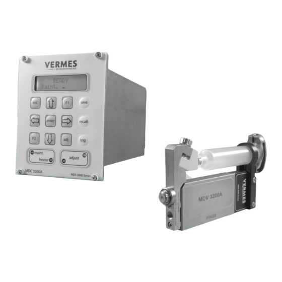
Control Unit MDC 3200A  4.1.1 Technical Data      Dimensions    128 mm H x 102 mm W x 173 mm D (w/o cable)  128 mm H x 102 mm W x 185 mm D (with cable)  3 HE x 20 TE  Weight  ca. 1500 g  Supply Voltage  110/230 V AC/DC  Supply Frequency  50/60 Hz  Current Consumption  900 mA max.   During start‐up, this value may be increased by a  factor of 5 (start‐up peak).  Recommended fuse: 16 A for 240 V resp. 110 V  Operating Temperature  0 °C  to 50 °C  Air Humidity  35 % till 95 % rH    Casing Type  Plug‐in case for 19“ rack  Color of Casing  Black, with lighter front plate  Ventilation  Convection  Internal storage locations:  10 (see page 21)  Display lines  2 lines with 16 characters each  Display illumination  White with background lighting ...
  • Page 15: Front Side

    4.1.2 Front Side                                              LC‐Display (two lines with 16 characters each):   Data, service intervals and menu options are shown in the two lines of the illuminated LC display.  The current menu option appears in the upper line, whereas the lower line contains the current  parameter value for dispensing, according to numerical data to be modified.     Keypad with twelve soft keys:  Menu options to control the system are selected by means of these keys.   Details for changing parameters etc. are explained in chapter 4.2, page 17.    Control lamp for service request:  As soon as this lamp lights up, the valve has to be returned to the manufacturer (or licensed sub‐ contractor) for regular periodic maintenance.     Control lamps for adjust:  The adjust for the valve is internally monitored; the result is visualized by means of these two control  lamps.   Green: The value is OK and can be confirmed by [enter]. ...
  • Page 16: Back Side

    4.1.3 Back Side                                        Thermocouple socket:  This element is intended for connection of thermocouples “Type K“.    Mains switch:  With this illuminated switch the unit is switched ON and OFF.     AUX socket:  This connector can be used for supply of an external device (e.g. an optocoupler).     Socket for heating:  The heater cable has to be connected here.    RS‐232C Interface (9‐pin):   Since the system offers the possibility of external programming of dispensing parameters via PC, a  local RS‐232C is integrated to receive the data. For the communication protocol, refer to page 38.    Sensor socket:  For the connection of the sensor cable.    Actuator socket: ...
  • Page 17: Function Keys

    Function Keys    Function Key  Function    Manual Trigger Key    Pressing the [trig]‐key instantaneously launches a dispensing procedure ac‐ cording to the selected parameter settings.    The [save]‐key opens the menu for storing current parameters. Ten storage  locations are available for distinct configuration sets. Each set contains values  for pulse parameters and the settings for heating and key interlock.    Select the desired storage location by means of arrow keys.       Press  to confirm.      Press  to cancel without saving the selection.    Parameter sets saved in the internal memory can be retrieved any time using  the [recall]‐key.     Select one of the ten internal storage locations by arrow keys.      Press  to confirm the selection.    Press  to abort.     The [adj]‐key is used to start the adjust (see page). It is required during each  initial operation and after an exchange of the nozzle unit.  With this procedure the position of the nozzle insert with respect to  the tappet is preselected.    Pressing the [enter]‐key confirms the menu selection and opens the corre‐...
  • Page 18   The screen moves one menu step back.  ... or ...  The cursor is shifted one position to the left.   ... or ...  A parameter is modified.    The screen moves one menu step ahead.  ... or ...  The cursor is shifted one position to the right.   ... or ...  A parameter is modified.    The [F1]‐key opens the valve, taking into consideration the current values for  “Rising” and “Falling”. The valve remains opened, until the key is released.  Maximum length: 2 min. Then the valve closes automatically in order to pro‐ tect the actuator.    Not used in the present configuration.            VTK‐VS‐BA‐004e‐B  |  User Manual MDS 3200A | Product Description...
  • Page 19: Menu Structure

    Menu Structure  Three menus can be accessed from the main menu:   “Pulse Parameter“, “Heating“ and “Status“.     You can recall and modify dispensing parameters for a particular process in the submenu  “Pulse Parameter“.    “Heating“ – select the settings for the heating.    Relevant data for our Technical Support are contained in submenu “Status“. This function can  also be used by the client to decide on individual cycles for the replacement of tappet and noz‐ zle insert (see page 59). The current state of the system with respect to the maintenance inter‐ val can be verified by function “Maint. Cycle“ (see page 59), messages concerning the correct  behavior of the system by function “Error“. Troubleshooting is detailed in chapter 10.  4.3.1 Main Menu  4.3.2 Submenu “Pulse Parameter“  VTK‐VS‐BA‐004e‐B  |  User Manual MDS 3200A | Product Description...
  • Page 20: Submenu "Heating

    4.3.3   Submenu “Heating“  Two distinct options (MDH 230te and MDH 230tf) are available to heat the nozzles of the  microdispenser MDS 3200A. This way the dynamical viscosity of the fluid to be dispensed can be  controlled, for some liquids dispensing without heating is even impossible.    Heating may also be required to ensure a constant process temperature, or when the dispensing  has to take place above room temperature.     Selection of temperature values as well as switching ON and OFF of the heaters is carried out by  means of the functions illustrated below.                            4.3.4 Submenu “Status“    The first three functions “Firmware version“, “Valve ID“ and “ID Control Unit“ with the particular  serial numbers represent important information when consulting the Technical Support.    “Maint. Cycle” refers to the unit as a whole and cannot be modified by the user. For the nozzle and  the tappet however, it is possible to determine a fix number of cycles before replacing the concern‐ ing items and to reset the counters after exchange. “Error” shows corresponding messages of the  system.                ...
  • Page 21: Memories Of The Mdc 3200A

    Memories of the MDC 3200A  The MDC controller unit contains several memories to save parameter set‐ups. The first one is the  RAM (Random Access Memory). Here the parameters of the current dispense process will be  saved. This memory will be erased when the controller is switched of or disconnected from power.  When starting again, the RAM will load the data from the first of eleven parameter memory sets  saved on the EEPROM (Electrically Erasable Programmable Read Only Memory). This first parame‐ ter set is also called the “EEPROM current working parameter configuration”, or short also “work‐ ing configuration” or “EEPROM working configuration”.  The parameter set in the “EEPROM working configuration” is usually the same as the parameter set  saved in the RAM memory. When using the touch panel to program the controller, the two memo‐ ries will always have the same contents. The only way to create a difference in the parameter set  saved in the RAM and in the EEPROM working configuration is by using some special commands  through the RS‐232C (page 38).  The remaining ten EEPROM memory sets can be used to saved different parameter set‐ups when  programming the controller through the touch panel interface (use the command [save]).  In order to change the values saved in the EEPROM working configuration you may use the MDC  keypad (press “enter”, “pulse parameter”).   Or you may use one of the following commands via RS‐232C:  “TRIGGER:SET:<Rising>,<Open Time>,<Falling>,<Needle Lift>,<Number of Pulses>, <Delay>,1”  “TRIGGER:ASET:<Rising>,<Open Time>,<Falling>,<Needle Lift>,<Number of Pulses>, <Delay>,1”  All values transmitted to the MDC 3200A by one of the following two commands will not be saved  in the EEPROM working configuration:  TRIGGER:SET:<Rising>,<Open Time>,<Falling>,<Needle Lift>,<Number of Pulses>, <Delay>  TRIGGER:ASET:<Rising>,<Open Time>,<Falling>,<Needle Lift>,<Number of Pulses>, <Delay>   Instead it will remain in the RAM memory until overwritten by another RS‐232C command, or  when the MDC 3200A is switched OFF and the EEPROM is read out into the RAM during restart.  The reason for having these two different types of commands (the distinction is the “1” at the end)  is that it takes up to 1 sec to save the parameter set in the EEPROM.   Please be aware that there will be a difference between the parameter settings saved in the RAM  and in the EEPROM working configuration when using the command TRIGGER:SET (without 1)  through the RS‐232C. This may explain some unexpected behavior of the system.  On top of the working configuration and the 10 parameter setups there is another parameter set‐ ting saved in the software on the EEPROM. This is called the “factory setting”. It cannot be changed  by the user. It may be loaded to the “working configuration” and the RAM memory after major dis‐ turbances of the system.         VTK‐VS‐BA‐004e‐B  |  User Manual MDS 3200A | Product Description...
  • Page 22: Microdispensing Valve Mdv 3200A

    Microdispensing Valve MDV 3200A  4.5.1 Composition  The Microdispensing valves of Vermes Microdispensing are built modular. A valve is composed of  four different modules:    Electronics/Sensor Electronics (1)   Actuator System (2)   Fluid Box (3)   Nozzle Unit (4)                                      Module (1) accommodates the electronics, required to receive signals from actuator and sensor.   The connectors for sensor and actuator cable are integrated in the surface of the case; they have to   be linked to the control unit.    The actuator system (2), representing the core of the microdispensing valve, houses the sensor, the  piezoelectric element and the mechanics to drive the tappet. Actuator case and mechanics are  sealed for protection against dust and contamination.    The fluid box (3) is thermally isolated from the actuator system. Its purpose is to transport the liquid ...
  • Page 23: Specification

    4.5.2 Explosion View MDV 3200A with MDX 3080‐CC‐10       4.5.3 Specification  Parameter  Value  Dispensable Quantity  < 2nl up to > 200 µl per cycle (for highly viscous me‐ dium)  Inlet Pressure Range  0,1 to 70 bar (rel.)   0,1 to 8 bar with cartridge    0,1 to 70 bar with pressure tank  Dynamic Viscosity of Fluids  Medium and high viscosity up to 2.000.000 mPas  Response Time (PLC‐interface)  ca. 104 µs  Dispensing Frequency (max.)  2 kHz  Dispensing Frequency (average)  580 Hz (cooled)  Operating Temperature  from 10 °C to 50 °C  Compatibility  All aqueous fluids, organic solvents, weak acids and  bases   Dimensions (basic model)  115 mm x 39,5 mm x 12 mm  Weight  ca. 258 g (depending on configuration)  Position of Tappet in Absence of Voltage  open        VTK‐VS‐BA‐004e‐B  |  User Manual MDS 3200A | Product Description...
  • Page 24: Valve Types

    4.5.4 Valve Types  The MDV 3000 family comprises the following series   MDV 3010A (for low‐viscous fluids)   MDV 3020A (low and medium viscosity)   MDV 3200A (medium and high viscosity)   MDV 3200F (medium and high viscosity)      VTK‐VS‐BA‐004e‐B  |  User Manual MDS 3200A | Product Description...
  • Page 25: Special Features Of The Mdv 3200A

    To replace the nozzle unit (with adjusting nut, insert, tappet guidance and O‐ring) is quick and easy,  as this unit has the quick‐change feature. Afterwards you have to carry out the adjust, in order to  establish a convenient position of the unit with respect to the tappet. This way a reproducible pro‐ cess remains ensured.    Highest Flexibility  Due to the modular design of the series, nozzle units and fluid boxes can easily be exchanged. This  allows at any for a quick adaption of the system configuration to new applications. A comprehen‐ sive choice of accessories is also available for special situations.   These modifications can be performed in no time, avoiding downtimes for the process. Ordering  the equipment already at an early stage however is recommended; do not forget to specify the  relevant data (Valve ID etc.). Consult our Technical Support beforehand, if special parameters have  to be taken into consideration.     Functionality Independent of the Position  The functionality of the valves does not depend on the fitting position, considerably simplifying the  integration into an existing process.    User‐friendly Design  The control unit does not give rise to compatibility problems with respect to the other components  of a complex process structure. Service is possible by keypad or, thanks to the integrated RS‐232C,  by remote PC.    Comprehensive Material Selection  Only the best materials are used for the production of Vermes Microdispensing valves.   All parts in contact with the transported medium consist of high‐alloy special steel, rust‐  and acid‐resisting, or modifications of high‐duty polymers of the PEEK and PTFE family.    Seals are available in NBR, EPDM, Viton, Silicon and Perlast.   For nozzle inserts, special steel, plastics, ceramics and PEEK options are permanently in  store, allowing for perfect tailoring of the configuration to the needs of the particular  application.      VTK‐VS‐BA‐004e‐B  |  User Manual MDS 3200A | Product Description...
  • Page 26: Initial Operation

    INITIAL OPERATION  Delivery   VERMES systems are shipped in carefully packed state. Transport damages however can  never be totally excluded, and deadlines stated in insurance contracts should not be ex‐   ceeded.  5.1.1 Unpacking  For this reason, the merchandise has to be visually inspected immediately after receipt.   Detected damages must be notified to the carrier. As soon as the complaint has been con‐ firmed in writing, contact the responsible forwarder and inform VERMES Microdispensing.   Otherwise unpack the contained subcomponents and check the delivery for completeness.  5.1.2 Content  According to the purchase order, the following components may be included;   some of them are already preassembled:      Basic equipment:    1.   Control unit MDC 3200A         8. MDT 302 Nozzle Adjusting Tool  2.   MicroDispensingValve MDV 3200A    9. CD with user manual and software  3.   Fluid box*        10. MDT 304 Nozzle Insert – Squeezing Out Tool  4.   Nozzle unit*        11. Actuator cable (red)*  5.   Nozzle insert*      12. Sensor cable (yellow)*     ...
  • Page 27: Assembling The Mdv 3200A

    Assembling the MDV 3200A  INFORMATION! (some parts pre‐assembled)  Some elements of the equipment are delivered in preassembled state.   Proceed as follows:              Step 1:  Separate the nozzle unit from the fluid box. (1)              Step 2:  Mount a nozzle insert. (2+3)   Unscrew the tappet guidance from the nozzle adjusting nut. Use the nozzle exchanging  tool MDT 303.   Place the nozzle insert onto the tip of the tappet guidance; the large face of the nozzle  insert has to point down. Firmly reattach the tappet guidance to the nozzle adjusting nut.               Step 3:  Mount the nozzle unit. (4)   Screw the assembled nozzle unit (tappet guidance with seal, nozzle adjusting nut and  nozzle insert) to the fluid box (2‐3 rotations, to be executed manually).              Step 4:  Install the fluid supply. (5+6+7) ...
  • Page 28: Installation Of The Mdc 3200A

      CAUTION! (Read chapter “Safety” first)  The entire procedure of installation is reserved to persons reliably informed about the  safety considerations discussed in chapter 3.    5.3.1 Installation of the MDC 3200A  The control unit is designed as a 19“ plug‐in module, which has to be fixed in the corre‐ sponding rack by means of four pan‐head screws at the front side. Leave sufficient space  around the unit to simplify service. Ventilation should be available. We recommend cases  complying with enclosures according to EN 61010‐E with regard to fire protection.    Important Note! (Possible damage to the MDC)  Don’t turn the four pan‐head screws mentioned above too tight; otherwise the front plate  can be damaged.    To avoid overheating and ensure the required aeration, a minimum distance between the  control unit and any other object should be maintained (at least 1,5 cm). Heat should neither  be accumulated nor externally be introduced. Do not obstruct natural convection. Ventilation  from the bottom side and air exhaust from above is important. Minimum width of ventilation  openings is 8 cm x 8 cm.     For high‐duty applications (from ca. 300 Hz) or in the case of an air‐cooled model (AC vari‐ ants), a rack with separate ventilation is advisable, since in these situations an airflow of  100m /h for each MDC 3200A is compulsory.         VTK‐VS‐BA‐004e‐B  |  User Manual MDS 3200A | Initial Operation...
  • Page 29: Installation Of The Mdv 3200A Valve

    5.3.2 Installation of the MDV 3200A Valve  Preferably mount the valve on an automatic XYZ table or in a similar  device (XYZ positioning system). Stable seat at the fixture of Z axis is  imperative, as the valve should not become loose during the dis‐ pensing process. For this purpose, two M4 hex screws have to be in‐ serted to a depth of 4 mm, through the borings located at the nar‐ row side of the valve. Their distance to the center amounts to 45  mm. To improve accuracy when positioning the valve on a recepta‐ cle, additionally use the alignment boring and the long hole, located  on the narrow side of the valve as well.    IMPORTANT! (Corrosion)  In order to prevent corrosion, all parts used in connection with the valve (screws, fix‐ ing plates etc.) should consist of stainless steel, nonferrous metals or galvanized steel.  5.3.3 Connection of air‐cooling for MDV 3200A‐AC models  As soon as the installation of the valve is complete, connections for air‐ cooling have to be attached (with hose diameters of 3 and/or 6 mm, ac‐ cording to the particular model).    One end of the hose has to be inserted to the air inlet of the valve (1),  (the retaining sleeve automatically latches); the other one is connected  to the air supply.    The second connector (2), illustrated above, represents the outlet, evacuating the heated  compressed air from the valve. When running the hose to the air supply, take care not to  impair functions of the system, or to disturb operators during their work.    IMPORTANT NOTE! (quality of compressed air)  Quality of compressed air should comply with DIN ISO 8573‐1.     The pneumatic supply used for cooling of the MDV 3200A‐AC should be free of fine dust and  condensate, and correspond to classes 1, 3, 2 according to DIN/ISO 8573‐1.    Solid particles: 0,1µm max., admissible concentration 0,1 mg/m³ = Quality class 1   Water content: max. pressure dewpoint ‐20°C, admissible density: 0,88 g/m³ = Quality class 3   Residual oil: 0,1 mg/m³ max. = Quality class 2   5.3.4 Wiring of the MDS 3200A ...
  • Page 30: Actuator Cable

    5.3.4.1 Actuator Cable  Power to the piezo element is supplied by the actuator cable, which is wrapped with a red  antikink sleeve. The voltage range is ‐30 V to 120 V (bipolar operation).   Step 1:   Plug the cable into the correspondingly labeled connector on the rear side of the  control unit and screw it in place.  Step 2:   The other end, equipped with a LEMO connector (corrugated sleeve), has to be   inserted to the four‐pin bushing of the valve.     IMPORTANT NOTE! (Connecting cables)  Verify during the connecting procedure that the red points on plug and socket point  towards each other.  5.3.4.2 Sensor Cable  This yellow cable is provided to transfer data from the sensor integrated in the valve to the  control unit. The connection has to be performed as described above.   Step 1:  First fix it to the corresponding socket of the control unit.   Step 2:   The connector with corrugated sleeve has to be attached to the 5 pin socket  of the valve.    IMPORTANT NOTE! (Connecting cables)  Verify during the connecting procedure that the red points on plug and socket point  towards each other.    5.3.4.3 Mains Cable  The black mains cable supplies the power to the control unit.     IMPORTANT NOTE! (type plate)  Do not connect the system to the mains, before having checked the type plate of the  model to be installed (mains voltage, 110 VAC or 220 VAC).    Step 1:  Plug the cable into the socket at the bottom of the rear side of the control unit.  The rear side is illustrated in chapter 4.   Step 2:   A special shackle is provided, located just above the socket. Use this shackle to se‐ cure the mains cable from slipping off.  ...
  • Page 31: The Adjust

    The Adjust  The following segments explain the adjust. The description assumes you are controlling the  adjustment procedure directly via MDC. It is also possible to do it remotely via the RS‐232C  interface. The relevant information for this method can be found in chapter 7.1.2.  5.4.1 Purpose  The system is unable to perform a regular repeatable process, if the nozzle insert is not  properly positioned in relation to the tappet prior to dispensing. Therefore you have to per‐ form a general adjustment procedure (simply called “adjust”) during initial operation and af‐ ter each exchange of the nozzle unit. This is especially important to avoid any leakage during  dispensing.  5.4.2 Procedure  CAUTION! (cleaning before adjust)  The system has to be cleaned thoroughly before the adjust. The presence of dirt par‐ ticles jammed between the tappet surface and the nozzle insert would compromise  the results.    Step 1:   First unscrew the nozzle unit from the fluid box.  Step 2:  Initiate the procedure by pressing the [adj] key.  Step 3:  Use tool MDT 302 (or alternatively MDT 301, if necessary for spatial reasons) to  rotate the nozzle unit towards the fluid box, until the red control LED is lit. The in‐ dicated value displayed should amount to 1100 or slightly above.     IMPORTANT NOTE! (limit)  Maximum admissible display value is 1250, otherwise the tappet can break afterwards.    IMPORTANT NOTE! (careful installation)  Screw the nozzle unit onto the fluid box carefully. Avoid tilting the nut by tilting the  nozzle unit. This procedure requires sufficient concentration. If the tappet guidance  including the nozzle insert has not been installed correctly, the adjust may fail (see  page 27).    Step 4:  Rotate the nozzle unit counterclockwise, until the green LED is lit.   The displayed value should be in the range between 1030 and 1040.    IMPORTANT NOTE! (unstable values) ...
  • Page 32: Initial Liquid Supply

    Step 1:  If not using a prefilled cartridge, fill an empty one with the desired fluid, till up to  80 % of its capacity.  Step 2:   Insert the cartridge into the corresponding holder and screw it onto the luer‐lock  fluid box connector, rotating clockwise.  Step 3:   Place the compressed‐air adaptor onto the cartridge and rotate clockwise until it  latches in place.   Step 4:  Connect the PVC hose with coupler plug KS4‐CK‐6 to air supply. A coupler socket  type KD4‐1/2‐A is required.    CAUTION! (check for leakage)  All of the parts must be installed correctly, and the entire configuration must be leak‐tight –  otherwise the substance to be dispensed can trickle out in an uncontrolled manner.    Step 5:   After establishing a convenient dispensing pressure, activate the pneumatic supply.     Valves designed by VERMES Microdispensing can be operated at a relatively low supply  pressure, in the range between 0 and 7 bar. This upper limit should not be exceeded in nor‐ mal applications; in most cases even a value of 4 bar is sufficient.    Standard values:   Low‐viscous fluids (e.g. water): 0.5 – 1.5 bar   Medium viscosity (e.g. SMT‐adhesives): 1.5 – 2.0 bar   High viscosity (e.g. pastes): 2.0 – 7.0 bar    Removing Air Inclusions from the System  Air must be removed from the system, for instance after the exchange of a cartridge.   Save the current dispensing parameters beforehand (see page 36).     Confirm the following parameter selection:  Rising 0,5, Open Time 1,5, Falling 0,17, Delay 5–30, Needle Lift 75 and Number of Pulses 500‐2000    Dispense a quantity of ca. 500 to 2000 portions by pressing [trig].  ...
  • Page 33: Operation

    OPERATION  Triggering a Dispense Sequence  There are three different options to trigger a dispense sequence:   by touch panel on the MDC 3200A controller  press the [trig] button, a dispensing sequence with pre‐set parameters will be trig‐ gered   by RS‐232C   use the command “VALVE:OPEN“   by PLC command  real time triggering by direct I/O  Dispensing and Positioning of a Multitude of Dots  To combine a multitude of dots to a predefined structure (e. g. a line or a circle), use one of  the following four modes:   Burst Mode  A single trigger impulse by PLC signal causes a predefined number of dispense cycles.   ‐ Number of Pulses: predefined value (e.g. 1‐32000)     Single‐Shot Mode  Every dispense point is triggered by an individual PLC signal. When dispensing a continuous  feature (such as a straight line or a circle), the frequency of the dispense trigger signal  should be proportional to the trajectory speed of the axis system. This is necessary to  achieve a continuous line width.  ‐ Number of Pulses: “1”     Infinite Mode  Continuous dispensing as long as the PLC trigger input is “logic 1”. Dispensing will  stop when the signal is changed to “logic 0”  ‐ Number of Pulses: “infinite” (when programmed through touch panel)  “0” (when programmed through RS‐232C)     External Mode  The “External Mode” will shift the responsibility of time control of the parameter  “Open Time” to the higher level machine control. (This may require a very precise  time control of the higher level PLC.) As a result, the valve would function like a ...
  • Page 34: Parameters For Dispensing Process

    Parameters for Dispensing Process  The profile of the system behavior is illustrated below (Y axis = amplitude of the tappet).                    This diagram includes the following parameters:  Parameter  Description  Rising (RI)  This interval describes the time required until the valve is completely  opened. It is adjustable in steps of 0,01 ms.   Open Time (OT)  During this phase the valve remains in opened state. It is adjustable in  steps of 0,1 ms.  Max. Open Time for ≤ 80% NL = 3000 ms  Max. Open Time for > 80% NL = 15 ms    CAUTION!  When working in External mode, the cycle is initiated with the following  properties:   For Rising, Falling, Delay and Needle Lift, the values determined before‐ hand are used. Open Time however remains active, until the signal returns  to state “Logic 0“ (for Needle Lift ≤ 80 %).   Maximum Open Time for Needle Lift > 80 % is restricted to 15 ms.  Falling (FA)  The falling ramp of the curve illustrated above represents the time re‐ quired for closing the valve. Residual fluid meanwhile is expulsed from the  nozzle compression chamber (the cavity at the rear side of the nozzle in‐ sert). The interval is adjustable in steps of 0,01 ms.  Delay (DL)  This waiting phase between two cycles is adjustable in steps of 0,1 ms.  CAUTION!   For valves operated with connected heating systems, a minimum delay of  4,6 ms is necessary. Lower values can only be achieved, if the heater is  operated with an external control unit.  ...
  • Page 35: Minimum And Maximum Values Of Parameters

    Minimum and Maximum Values of Parameters  Parameter  Min. Value  Max. Value  Conversion Value  Rising (RI)  NL     1 % = RI 0.01 ms   300 ms  *10       NL   10 % = RI 0.03 ms    e.g.     NL   20 % = RI 0.06 ms  RI = 0,5 ms ≙ 5  NL   30 % = RI 0.09 ms   NL   40 % = RI 0.12 ms   NL   50 % = RI 0.15 ms   NL   60 % = RI 0.18 ms   NL   70 % = RI 0.21 ms   NL   80 % = RI 0.24 ms   NL   90 % = RI 0.27 ms   NL 100 % = RI 0.30 ms  Falling (FA)  NL     1 % = RI 0.01ms   300 ms  *10       NL   10 % = RI 0.01 ms   e.g.     NL   20 % = RI 0.02 ms  FA = 0,8 ms ≙ 8  NL   30 % = RI 0.03 ms   NL   40 % = RI 0.04 ms   NL   50 % = RI 0.05 ms   NL   60 % = RI 0.06 ms   NL   70 % = RI 0.07 ms  ...
  • Page 36: Input Of Values

    Input of Values  Modification of parameter values is simple. The name of the parameter appears in the up‐ per, the assigned numerical value in the lower line of the screen. If the last digit before the  decimal point is flashing, the value can be modified.     Increase by one  by arrow pointing upward.   Correspondingly,  the arrow pointing downward reduces the value by one.     This arrow         shifts the position of the active digit to the right.   To shift the active position to the left, use the left arrow.    Selection of other values (no numerical values) is performed similarly.      Use the right  or the left  arrow to switch between ON and OFF.     An input must be confirmed by  , to save the current selection.   Then the control returns to the next‐higher menu point.      To cancel without saving the current selection, press  . In this case, the screen also  returns to the next‐higher menu level.     IMPORTANT NOTE! (changing numbers)  When modifying a digit from “1“ to “0“, the cursor automatically jumps one position to the  right (if possible). The value in this position is set to 5, but can be modified as required.  Saving Parameter Sets  Ten storage locations are available to save pulse parameters of a menu, together with set‐ tings for heater and key lock.  Step 1:   Open the Store Menu with [save].  Step 2:  ...
  • Page 37: Loading The Factory Settings

    Loading the Factory Settings  By recalling the Factory Settings (implemented by the manufacturer), you return to a prede‐ fined starting position. This is useful to start the input of a new parameter set.  These are the values contained in the Factory Settings:   RI = 0,50 ms, FA = 0.20 ms, OT = 0 ms, NL = 90%, DL 10.0 ms and NP = 1    Step 1:  Press [recall].  Step 2:   [Downward Arrow] immediately opens this parameter set.   Step 3:   [enter] the selection.    IMPORTANT NOTE!  Press [esc] to abort.  Switching OFF the MDS 3200A  Step 1:   The current dispensing cycle must be completed, so that the valve is in home position.  Step 2:   Lower the supply pressure to atmospheric pressure (because in initial position, the  valve is still opened). Disengage the pneumatic supply. If required, close the car‐ tridge by using locking pin MDT 309.  Step 3:   Switch OFF the control unit (ON/OFF button at the rear end).  Step 4:   Disconnect the valve from fluid supply.  Step 5:   Remove all cables from the valve.  Step 6:   Unscrew the screws used for fixing the valve in place.   After working with self‐curing substances, immediate cleaning is advisable  in order to avoid clogging. This concerns the valve itself and all parts in con‐ tact with the fluid. The valve and its subcomponents have to be dismantled  and cleaned, as described in the chapter “Cleaning”.    CAUTION! (prepare cleaning)  It is recommended to prepare the cleaning procedure in advance.  Do not drop the device or its subcomponents.      VTK‐VS‐BA‐004e‐B  |  User Manual MDS 3200A | Operation...
  • Page 38: Communication Interfaces

    COMMUNICATION INTERFACES  Serial Interface RS‐232C: 9‐Pin Sub‐D            This local interface is structured according to SCPI Standard. These “Standard Commands for   Programmable Instruments“ represent a standardized set of instructions used for control and   programming, transmitted in form of ASCII text. They can be generated by any selectable pro‐ gramming language in any environment. The serial interface is operated by means of software  handshake. The hardware handshake communications are not in use.    INFORMATION! (Communication while triggering)   The user should bear in mind not to send instructions through this interface in the course of a run‐ ning dispensing cycle. Communication is only possible between distinct sequences.  After sending data or parameters to the control unit you have to wait for the “OK” signal before  you can start further actions.  7.1.1 Functions Allocated to the different Pins  PIN  Characteristics  Level  Function  ___________  ___________  1  Reserved for future use  2  Input  TX  Serial transmission signal  3  Input  RX  Serial reception signal  4      Connected to PIN 6  5 ...
  • Page 39: Rs-232C Commands

    7.1.2 RS‐232C Commands  The available commands are listed below. They are explained on the following pages, to‐ gether with short examples.   Each single instruction can be tested, e.g. by means of the “MDC Communicator“ software.  This software is contained on the CD which is included in the delivery. Information about  handling and installation of this software package can be found in chapter 7.1.3 (see page  50).    Reaction Time  RS‐232C Commands  *ESR?  450 ms  *IDN?  250 ms  ADJUST:?  250 ms  ADJUST:START  750 ms  HEATER:1:OFF  250 ms  HEATER:1:ON  250 ms  KEY:ENTER?  250 ms  KEY:ESCAPE?  250 ms  LCD?  250 ms  10. SYSTEM:KLOCK:OFF  250 ms  11. SYSTEM:KLOCK:ON  250 ms  12. TEMP:?  250 ms  13. TEMP:<setpoint in °C>  250 ms ...
  • Page 40 0  0  0  0    2.  *IDN?  Description:  Device specific information, formatted as follows: manufacturer, model,    software version. Important for contact with our Technical Support.    Example:      Input:  *IDN?      Result:  VERMES, MDV3200A, 065.411.001      Return:  VERMES, MDV3200A, 065.411.001        3.  ADJUST:?    Description:  This instruction is used to verify the success of the adjust. The result  consists in one of the following options:    Result: 0  Unknown State. The system is not able to interpret the question and  has to be switched OFF and ON again. The adjust must be repeated. This  event however is an exception.   Result: 1 ...
  • Page 41   Return:  2    The nozzle is correctly adjusted. The adjust was successful.    4.  ADJUST:START    Description:  Sending this instruction causes the adjust to be executed at once. This  procedure, required during each initial start‐up and after replacing the  nozzle unit, decides on the position of the nozzle insert with respect to  the tappet. The result has to be verified by the previously described  command no.3.    Example:          Input:  ADJUST:START      Result:  The adjust is initiated.      Return:  OK    5.  HEATER:1:OFF    Description:  The heater connected to the socket is switched OFF.    Example:     ...
  • Page 42 9.  LCD?    Description:  This command is useful to inspect externally the current content of  the screen.    Example:          Input:  LCD?      Result:  When sending this command immediately after switching  ON, the content of the screen will be “READY Maint.“      Return:  (in this case) “Ready Maint.“      10.  SYSTEM:KLOCK:OFF    Description:  Access to keypad is permitted, the locking function disabled.    Example:          Input:  SYSTEM:KLOCK:OFF      Result: ...
  • Page 43   Description:  This command is useful, if the user wishes to estimate the date of the next  exchange or maintenance.    Example:          Input:  MAINT:STATUS      Result:  Current percentage of the preset number of cycles (limit).      Return:  Maintenance: 0 %  Nozzle: 20 %  Tappet: 10 %       15.  TRIGGER:SET:?    Description:  The parameter set present in RAM is displayed, in the following order:  Rising, Open Time, Falling, Needle Lift, Number of Pulses, Delay.    Ramp parameters (i.e. values relating to time) are indicated in 1/10 ms,  except for “Falling“ which is given in 1/100 ms. If the valve currently is  operated in External Mode, the value for “Open Time“ is “EXTERNAL“. In  Infinite Mode, the Number of Pulses is always “0”.    Example:         ...
  • Page 44 Ramp parameters (i.e. values relating to time) have to be specified in 1/10  ms, except for “Falling“ which has to be entered in 1/100 ms. Values lower  than “1” are not admissible. Therefore the minimum Falling value amounts  to 0,01 ms (10 % NL), the minimum Rising value 0,1 ms (1 % NL).     Specified values must be integer and positive. If the External Mode is de‐ sired, instead of a numerical value, enter “EXTERNAL” for “Open Time”.   The start of a dispensing cycle with the selected parameter configuration is  initiated by the command “VALVE:OPEN“ (instruction no. 21, see below).    Example:          Input:  TRIGGER:SET:10,10,15,90,20,8      Result:  This way, the following values are assigned to the parameters:  Rising: 10 ≙ 1,0 ms (ms = Millisecond)  Open Time: 10 ≙ 1,0 ms  Falling: 15 ≙ 0,15 ms  Needle Lift: 90 %  Number of Pulses: 20  Delay: 8 ≙ 0,8 ms      Return:  OK    18.  TRIGGER:SET:<Rising>,<Open Time>,<Falling>,<Needle Lift>,<Number of Pulses>,<Delay>,1    Description:  With this command cycle parameters can be modified and saved in the  EEPROM of the control unit (Reaction time: 1200 ms). The entered set thus  remains available for future use. A trigger command however is not  launched, but can be initiated by means of command no.21 “VALVE:OPEN“,  so that a dispensing cycle with this parameter set immediately starts.  ...
  • Page 45 19.  TRIGGER:ASET:<Rising>,<Open Time>,<Falling>,<Needle Lift>,<Number of Pulses>,<Delay>    Description:  This instruction is used to modify cycle parameters without transmitting the  trigger signal. The values for both of the parameters “Falling” and “Rising”  are specified in steps of 0,01 ms. Minimum value for “Falling“: 0,01 ms  (10 % NL), for “Rising“ 0,01 ms (1 % NL). All other time parameters are en‐ tered in units of 0,1 ms, as usual.     Specified values must be integer and positive. If the External Mode is de‐ sired, instead of a numerical value enter “EXTERNAL” for “Open Time”.     The start of a dispensing cycle with the selected parameter configuration is  initiated by the command “VALVE:AOPEN“ (instruction no. 22, see below).    Example:          Input:  TRIGGER:ASET:55,10,8,80,20,8      Result:  The following values are assigned to the dispensing   parameters:  Rising: 55 ≙ 0,55 ms (ms = Milliseconds)  Open Time: 10 ≙ 1,0 ms  Falling: 8 ≙ 0,08 ms  Needle Lift: 80 %  Number of Pulses: 20  Delay: 8 ≙ 0,08 ms      Return:  OK    20.  TRIGGER:ASET:<Rising>,<Open Time>,<Falling>,<Needle Lift>,<Number of Pulses>,<Delay>,1 ...
  • Page 46 21.  VALVE:OPEN    Description:  This command initiates a dispensing cycle with the parameter combination  currently selected. Ramp parameters are indicated in 1/10 ms, except for  “Falling“ which is given in 1/100 ms.    Example:          Input:  VALVE:OPEN      Result:  Let us assume that the following configuration has   been selected:  Rising: 10 ≙ 1,0 ms (ms = Milliseconds)  Open Time: 10 ≙ 1,0 ms  Falling: 15 ≙ 0,15 ms  Needle Lift: 90 %  Number of Pulses: 20  Delay: 8 ≙ 0,8 ms  The system simply accepts this set and launches a corre‐ sponding dispensing cycle.      Return:  OK    22.  VALVE:AOPEN    Description:  This command initiates a dispensing cycle with the parameter combination  currently selected. The parameters “Rising“ and “Falling“ are displayed in  1/100 ms, in contrast to the other parameters which are given in 1/10 ms.   ...
  • Page 47   Example:          Input:  VALVE:OPEN: 30,10,15,90,20,8      Result:  The initiated cycle comprises the following values:  Rising: 30 ≙ 3,0 ms (ms = Milliseconds)  Open Time: 10 ≙ 1,0 ms  Falling: 15 ≙ 0,15 ms  Needle Lift: 90 %  Number of Pulses: 20  Delay: 8 ≙ 0,8 ms      Return:  OK    24.  VALVE:AOPEN:<Rising>,<Open Time>,<Falling>,<Needle Lift>,<Number of Pulses>,<Delay>    Description:  This command corresponds to instruction no. 23 described above. In this  case however, both of the parameters “Rising“ and “Falling“ are specified  in steps of 1/100 ms, in contrast to the other ramp parameters (1/10 ms).   Specified values must be integer and positive. If the External Mode is de‐ sired, instead of a numerical value enter “EXTERNAL” for “Open Time”.   Also in this case, parameters previously entered by “TRIGGER:SET“ are not  erased, but the combination remains in the system only until the end of  the cycle. Therefore, if the user does not wish to reenter the entire com‐ mand several times, the “TRIGGER:SET“ command is advantageous, since  here the cycle can be reactivated simply by “VALVE:OPEN“, as desired.    Example:     ...
  • Page 48   27.  WRITE:LCD:<text>    Description:  With this command, an ASCII text including up to 32 characters can be  written on the screen. All of the letters appear in form of capital letters.    Example:          Input:  WRITE:LCD:Hello World or WRITE:LCD:HELLO WORLD      Result:  The LC‐Display shows:  HELLO WORLD      Return:  OK    28.  SYSTEM:SHOW:CYCLES    Description:  The current value of the cycle counter is indicated.    Example:          Input:   SYSTEM:SHOW:CYCLES      Result: ...
  • Page 49 33.  TAPPET:SET:<value>    Description:  By this command, the user can decide on the number of cycles to be per‐ formed until the next maintenance of the tappet. After maintenance, reset  counter by command no. 32 described above.  If no selection is made, the value remains “infinite”.    Example:          Input:  TAPPET:SET:500000      Result:  500000 cycles have been selected.      Return:  OK    34.  NOZZLE:SET: :<value>    Description:  This command determines the number of cycles to be performed until the  next maintenance of the nozzle insert. After maintenance, reset counter by  command no. 35 described below.    Example:          Input:  NOZZLE:SET:500000   ...
  • Page 50: Mdc Communicator Software

     Open folder “MDC Communicator“.   Open folder “installer 1.2“.   Execute setup file (size 1,391 KB).  Step 2:   Wait until the installation is prepared.  Step 3:   Choose the directory required for installation of the program.  Step 4:  Accept the license agreement and press “NEXT“.  Step 5:   Press “NEXT“ once more to start the installation which may last some minutes.   Return to the preceding window by pressing “BACK”.  Step 6:  When the installation is complete, press “FINISH“.  Step 7:   Choose between the three options “Restart“, “Shut Down“ and “Restart Later“.    INFORMATION!  VERMES Microdispensing recommends restarting the PC.    Step 8:   The program is available immediately after restart.     7.1.3.2 Start  Step 1:   Connect the PC and the control unit with a straight interface cable.   Step 2:   Start the software via Start Menu.  Step 3:   Specify the port to be used for the connection of the control unit (Com1 is preferred).  Step 4:  The software automatically recognizes the control unit, notifying “HV detected“.  7.1.3.3 Input of Commands and Parameters   Step 1:   The Selection Screen “MENU“ presents an overview of available orders.  ...
  • Page 51: Plc-Interface: 15-Pin, Sub-D

    PLC‐Interface: 15‐pin, Sub‐D            The PLC‐interface (illustrated above) works on digital basis without a particular syntax. It al‐ lows for controlling a machine or device by means of a remote master device. Transmission  of data is possible in either direction. The trigger range of this interface amounts to 500 μs.  Access is possible to:   Status bits   Values of voltage and current   Set‐Trigger‐signals initiating dispensing cycles (pulses) or complete packages of pulses (bursts)   7.2.1 Pin Functions  PIN  Characteristics  Level  Function  ___________  ___________  Reserved for future use  1  2  Input  0 / +24 V  Trigger Voltage Input  =1.3 k  0 ... +5 V “Valve closed“  +12 V ... +30 V “Valve opened“  Positive edge triggering  3  Input  0/ +5 V  Trigger Voltage Input  =400   0 ... +0.8 V “Valve closed“  +3 V ... +5 V “Valve opened“ ...
  • Page 52: Remote Adjust

    7.2.2 Remote Adjust   7.2.2.1 Purpose  During a remote adjust, as opposed to the normal procedure (see page 31), the system is  operated from a master device (e.g. a PC), by means of interfaces (PLC, RS‐232C). The func‐ tion itself is identical.  7.2.2.2 Advantages  The remote adjust allows for total control of an MDC 3200A integrated in a machine, since  dispensing parameters can be monitored by the software of this machine. The control unit  can be built in with permanent key lock. Thus the modification of parameters without au‐ thorization can be prevented in the machine software.   7.2.2.3 Procedure  The remote adjust has to be performed according to the following instructions:     INFORMATION! (Displaying remote adjust)   In the course of the entire procedure, both adjust LEDs are lit simultaneously.   The display meanwhile shows “Remote Adjust is running!”   For transmission of the orders between PC and control unit, both of the interfaces  (RS‐232C as well as PLC‐interface) are used.    Step 1:   Send the command “ADJUST:START“ to the control unit via RS‐232C. The system  returns the message “Unscrew nozzle press enter“.  Step 2:   The nozzle unit must completely be detached, so that the tappet becomes visible.   Step 3:   In order to confirm step 2, a short trigger signal (500μs – 80 ms) must be sent to  the control unit – via PLC‐interface. The system then returns the current “Adjust  Value”, continuously repeating the transmission to the PC in intervals of 500 ms  (via RS‐232C).   Short Trigger signal:   5 V or 24 V (PIN2 + PIN4 or PIN3 + PIN4 Input signal of MDC via 15 pin Sub‐D)   Signal length: 500 μs – 80 ms  An additional command to update the adjust value on the screen is therefore not ...
  • Page 53: Cleaning

    CLEANING    After every dispensing process involving aggressive or self‐curing substances, a cleaning pro‐ cedure is recommended. It should involve the valve and all other surfaces in contact with  the fluid. Different methods of cleaning are described in the following chapter. The proper  choice depends on the degree of contamination and the dispense medium used.  Preliminary Notes  IMPORTANT NOTE! (prepare cleaning in advance)  It is recommended to prepare the cleaning procedure in advance.   Do not drop the device or its subcomponents.    CAUTION! (liquid spurts possible)  Personnel must be aware of the fact that residual liquid may drain OFF or spurt when  handling components. Therefore protective clothes are recommended, like   ‐ Safety goggles  ‐ Gloves and overall (chemical resistant)    Remember that the surface of the valve is sensitive to abrasion, so do not use wire  brushes and other inappropriate tools. A specially developed cleaning tool kit (CTK) is  available upon request (order no. 1010320), which is of particular interest for all sur‐ faces in direct contact with the fluid.     WARNING! (potential chemical reactions)  The dispensed medium and the cleaning agent to be used must be compatible to each  other and should not give rise to chemical reactions, toxic vapor, increase of tempera‐ ture etc.! Information can be found in the corresponding safety data sheet; consult  the manufacturer in case of doubt.    Before introducing aggressive purifying agents or solvents to the system, verify com‐ patibility with the material of all adjacent parts (refer also to the corresponding list,  page 54, and consult our Technical Support in case of need).     CAUTION! (keep actuator clean)  No liquid should penetrate into the actuator (e.g. through the plug); otherwise the  whole element could be damaged.      VTK‐VS‐BA‐004e‐B  |  User Manual MDS 3200A | Cleaning...
  • Page 54: Compatibility Between Sealing Material And Selected Medias

    Compatibility between Sealing Material and Selected Medias      NBR  EPDM  VITON  SILIKON  PE  PTFE  Acetone  ‐‐‐  +++  ‐‐‐  ‐  +  +++  +++  Ammonia  ‐‐‐  ‐‐‐  ‐‐‐  +++  +++  +++  Chloroform  ‐‐‐  ‐‐‐  +++  ‐‐‐  +++  +++  Cyclohexane  +++  ‐‐‐  +++  ‐‐‐  +++  +++  Hexahydrophenol  +++  ‐‐‐  +++ ...
  • Page 55: Cleaning Methods

    Cleaning Methods  The following methods are available:   Pre‐purifying   Rinsing with a purifying agent   Total disassembly of the valve, followed by fine purification  8.3.1 Pre‐purifying  Pre‐purifying consists in purging the system with compressed air.    CAUTION! (potential liquid spurts)  During this procedure, liquid droplets may be expulsed!   Users must protect themselves correspondingly.    Step 1:   The dispensing process must be completed. The valve is in closed position.   Do NOT switch OFF the control unit.   Step 2:  Separate the compressed‐air connection.   The pressure must be reduced to 0 bar.   Disconnect the PP adapter fitting from the cartridge.  Step 3:  Replace the used cartridge by a new one.  Step 4:  Reinstall the compressed‐air as follows:   Place the PP adapter fitting on the cartridge. Rotate clockwise, until it latches in place.   Connect the PVC hose with the KS4‐CK‐6 coupler plug to a compressed‐air supply. For  this purpose you require a KD4‐1/2‐A coupler socket.    Activate the compressed‐air supply.  Step 5:  Place a container underneath the valve, to collect any liquid dripping out.  Step 6:  Initiate the purging procedure by pressing [F1].   Keep the [F1] key pressed until the procedure is complete and no more liquid ...
  • Page 56 8.3.2 Rinsing with Purifying Agent  After pre‐purification by compressed air, residual liquid may still be present inside the fluid  system (particularly when dispensing high‐viscous substances). You can only remove it with a  flushing procedure. For this purpose, the following agents may be suitable:      Distilled water   Ethanol   Isopropanol (IPA)   Acetone    WARNING! (potential chemical reactions)  Before the start of the procedure, carefully read the safety data sheet of the dis‐ pensed substance. Ensure compatibility with the cleaning agent. The cleaning agent  itself should not react with any part in contact with the fluid. Consult the manufactur‐ er in case of need, especially if aggressive material is intended to be used. In case of  need, consult the manufacturer.     Step 1:   The dispensing process must be completed. The valve is in closed position.   Do NOT switch OFF the control unit.  Step 2:  Separate the compressed‐air connection.   The pressure must be reduced to 0 bar.   Disconnect the PP adapter fitting from the cartridge.  Step 3:  Replace the used cartridge by a new one. The purifying agent can be supplied.    CAUTION!  All of the connectors must be installed and leak‐tight.    Step 4:  Reinstall the compressed‐air connection as follows:   Place the PP adapter fitting on the cartridge. Rotate clockwise, until it latches in place.  ...
  • Page 57: Dismantling The Valve And Fine Purification

    8.3.3 Dismantling the Valve and Fine Purification  Step 1:   The dispensing process must be completed. The valve is in closed position. Switch  OFF the control unit and disconnect it from the mains.   Step 2:   Deactivate the compressed‐air connector and disengage it.  Step 3:   Remove actuator and sensor cable from the valve.  Step 4:   Disassemble the valve as follows:   Unscrew and remove the cartridge.   Loosen the two screws for the cartridge holder. Remove the holder.   Detach the Luer Lock connector from the cartridge base. If necessary, use a wrench  no. 8.    Disconnect the sealing nut with tool MDT 302. Remove it together with the cartridge  base.    Disconnect the nozzle unit, rotating counterclockwise.   Disassemble this unit.   Unscrew the tappet guidance, together with the nozzle insert, from the nozzle adjusting  nut. Use the nozzle changing tool MDT 303. Afterwards pull off the O‐ring from the tap‐ pet guidance.   Remove the two connecting screws in order to separate the fluid box from the valve.       CAUTION! (beware of tappet while disconnecting)  Be careful when disconnecting the fluid box. The tappet can break, if the fluid box is  jammed.     Disengage the tappet centering piece and tappet sealing from the fluid box. Use the  thicker side of tool MDT 304 for this purpose.  Step 5:   Prewash all of the components by hand. The proper use of the parts contained in  cleaning tool set CTK is illustrated on the following page (see page 58). Each of ...
  • Page 58: Fine Purification Of Components

    8.3.4 Fine Purification of Components     VTK‐VS‐BA‐004e‐B  |  User Manual MDS 3200A | Cleaning...
  • Page 59: Maintenance

    MAINTENANCE  Maintenance Indicator  The integrated “Cycle Count“ function relates to the valve as a whole and is predetermined  by the manufacturer. As soon as the preset number of cycles is complete (100 %), the red  “maint” LED on the control panel is lit. The manufacturer (or an authorized subcontractor)  has to be informed at once.  In between, you can inspect the current state. Use the function “Maint. Cycle” in the sub‐ menu “Status” (see chapter 4.3.4). The result is visualized by eight bars on the screen, each  of them representing 12.5 % of the final value.  Additional cycle numbers can individually be agreed for tappet and nozzle insert. In factory  settings, the value of “Infinite” is assigned to both of the targets. If the user wishes to enter  a particular value, proceed as follows, starting from the first menu level:    1x [Right Arrow]‐key = Indicates the interval for exchange of the nozzle insert   2x [Right Arrow]‐key = Indicates the interval for exchange of the tappet  To enter a desired final value, you have to use the functions “Set Nozzle” for the nozzle and  “Set Tappet” for the tappet. They are located in the submenu “Status”. Results are also dis‐ played in the form of 8 bars, each of them representing 12.5 % of the total value. Once  100 % are reached, the red “maint” LED is lit. The corresponding item (nozzle or tappet) has  to be exchanged. After the exchange you have to reset the corresponding counter to “0”.  Use the functions “Reset Nozzle” or “Reset Tappet” in submenu “Status“ (see chapter 4.3.4).  Exchange of Tappet Sealing For replacement of seals, a particular counter is not provided, as the necessity depends on  current applications, substances to be dispensed etc.   Some  materials,  caused  by  the  tappet  movement,  tend  to  penetrate  between  tappet  and  sealing. This is giving rise to abrasion, so that the sealing has to be inspected from time to  time.  Continuously  working  with  damaged  sealing  inevitably  entails  unexpected  interrup‐ tions, loss of material and an increased need of cleaning. In some cases, even the actuator ...
  • Page 60: Maintenance Of The Tappet

    Maintenance of the Tappet  As the tappet belongs to the wearing parts of the system, it has to be greased and ex‐ changed in regular intervals or in the case of problems (as soon as it starts to move in a  sluggish way). The exchange procedure depends on the particular tappet model; ceramics  (two versions, CT and CTF) and tungsten carbide (TTF) items are available.     CAUTION! (properly trained personnel)  To avoid major damages, these procedures have to be carried out by personnel with proper  training.    CAUTION! (use tool MDT 310)  For dismantling and installation, the tappet changing tool MDT 310 is required (see page 9).  9.3.1 The CT‐tappet (ceramics tappet)              9.3.1.1 Demounting  Step 1:  Carefully remove the nozzle unit from the fluid box. (1) Step 2:  Both M2.5 hexagon screws of the fluid box must be loosened and un‐ screwed. Slowly slide away the fluid box from the tappet. The fluid box  must not be jammed; otherwise the tappet may break off! (2)  Step 3:  To unscrew the tappet itself, proceed as follows:   Tool MDT 310 features a receptacle boring for the tappet. This boring has to  be pushed carefully over the tappet, until the studs of the tool latch in the cor‐ responding recess of the tappet centering screw (3).   In order to disengage the tappet, rotate the tool counterclockwise, with a  slight constant pressure (4).    Separate the tool from the tappet. The tappet can now be removed through  the case boring of the valve (5).   9.3.1.2 Installation ...
  • Page 61: Greasing And Remounting

    9.3.1.4 Greasing and Remounting  Step 1:  Push the tappet spring onto the rod and grease at point A1 and A2. Make  sure to avoid getting grease on the tip of the tappet.  Step 2:  The actuator tight seat must be reinstalled on the rod. It is important, that  the short face of the seat is located in the spring.  Step 3:  Slide the new O‐rings onto the rod, until they contact the long side of the  actuator tight seat. Grease point A3.  Step 4:  While slowly rotating, push the tappet centering screw onto the actuator  tight seat. The recess of the centering screw (for the tool) must point to‐ wards the tappet tip.  Step 5:  The complete spring (A4) must be coated with a small amount of grease.  The tappet can be inserted, and the dispensing process may be continued after the adjust.  9.3.2 TTF‐ and CTF‐tappet            9.3.2.1 Demounting  Step 1:  Carefully remove the nozzle unit from the fluid box. (1) Step 2:  Both M2.5 hexagon screws of the fluid box must be loosened and un‐ screwed. Slowly slide away the fluid box from the tappet. The fluid box  must not be jammed, otherwise the tappet may break off! (2)  Step 3:  To unscrew the tappet itself, proceed as follows:   Tool MDT 310 features a receptacle boring for the tappet. This boring has to  be pushed carefully over the tappet, until the studs of the tool latch in the cor‐ responding recess of the tappet centering screw (3).   In order to disengage the tappet, rotate the tool counterclockwise, with a  slight constant pressure (4).  ...
  • Page 62: Error Messages

    ERROR MESSAGES    The following pages list all the error messages you could encounter when using a MDS 3200F  system. In case of an error, an error message is shown in the display and the red adjust LED is  switched “ON“. Press [enter] to clear the display. If this does not work, switch “OFF“ the control  unit. Check the system for potential problems (e.g. loose cables) and re‐start the system. After  completion and restart, the message does not appear on the screen again, but remains stored in  the “Error“ Menu (see page 20). If the problem still persists, consult our Technical Support.    1  INVALID VALVE DATA ERROR 101    This  message  sometimes  appears  during  startup  of  the  system:  The  control  unit  does  not  recognize the valve resp. the required valve type.    Error Code Display:  INVALID VALVE DATA ERROR 101  Error Code Status Menu:  VALVE ERROR 101     The sensor connection has not been plugged in correctly.  Corrective Action:    Switch OFF the control unit and inspect the connection.     If the cable turns out to be damaged, it must be exchanged  before restarting. ...
  • Page 63   5  VALVE NOT PRESENT ERROR 302      With system in operation, the communication between valve and control unit is disrupted.      Error Code Display:  VALVE NOT PRESENT ERROR 302  Error Code Status Menu:  VALVE NOT PRESENT ERROR 302       Switch OFF control unit, and verify both of the connections  Corrective Action:    (sensor and actuator cable).       Defective cables must be exchanged.    Otherwise, the valve must be returned to the manufacturer.      6  VALVE DEFECT ERROR 501      The valve during operation fails, e.g. due to a damaged piezoelectric element.    Error Code Display:  VALVE DEFECT ERROR 501    Error Code Status Menu:  VALVE DEFECT ERROR 501      Corrective Action:  ...
  • Page 64     9  INTERNAL ERROR 701    A hardware failure of the valve control is probable (e.g. short circuit in the connection of the    piezoelectric element). This problem is possible during startup of the control unit and also    with system in operation.   Error Code Display:  INTERNAL ERROR 701    Error Code Status Menu:  DAC LOAD ERROR       The control unit must be switched OFF, at once. Inspect the  Corrective Action:    actuator cable connection. Worn, kinked or charred cables      must be exchanged.   The valve must be returned to the manufacturer. The MDC  has to be checked.    10  EEPROM Error Press Enter    A corrupted memory area becomes obvious when reading the EEPROM.        Error Code Display:  EEPROM Error Press Enter  Error Code Status Menu:  EEPROM NOT FORMATED ...
  • Page 65   14  Watchdog Time Out Press Enter    Abnormal end (crash) of the control unit.         Error Code Display:  EEPROM Error Press Enter  Error Code Status Menu:  WATCHDOG TIMEOUT       The message has to be acknowledged by [enter].   Corrective Action:      The control unit restarts.      15  ERROR 999  The problem cannot be assigned to any error other code of the list.        Error Code Display:  ERROR 999    Error Code Status Menu:  ERROR 999    Switch OFF the control unit, and switch it on again after ca.  Corrective Action:      15 sec. The message is reported in the error list, with no   ...
  • Page 66: Transport, Storage And Disposal

    TRANSPORT, STORAGE AND DISPOSAL  11.1 Transport  For shipment, the system is packed in an appropriate case. Preserve it for further transport  procedures in the future. The necessity can never be excluded, e.g. for purposes of mainte‐ nance. The following measures should be followed:   The system should only be shipped in completely decontaminated state. Fill out  the corresponding form (see page 75), and attach it, clearly visible, at the exterior  of the package.   If the original packaging is not available, select a suitable material and protect the  delivery against shock and vibrations. Empty spaces should be filled with appro‐ priate material (e.g. paper, insulating air cushion, Styrofoam).    IMPORTANT NOTE! (decontamination)  The customer is liable for all consequences resulting from insufficient decontamination of  the system (health of transport personnel)!   11.2 Storage  The environmental conditions in the room intended for storage should fulfill the require‐ ments of the system.   The room should be sufficiently ventilated and free of dust    Admissible temperature: Between ‐10°C and +30°C   Rel. humidity < 50%   The system should not be stored together with fuel, solvents, lubricants, acids and  other chemicals able to develop vapors which may aggress to the surface of the  components.   Air‐tight foil sheathing with included desiccants may be useful.   11.3 Recycling and Disposal       The entire packaging consists of 100% recyclable material.      ...
  • Page 67: Spare Parts

    SPARE PARTS    Nozzle Adjustment Nut          NAN‐fix H “NBR“    NAN‐universal   NAN‐MDH 230tf     order.no. 1010549 order.no. 1012967    order.no. 1009012             NAN‐universal +10 mm    NAN‐fix‐33  Tappet Guidance   order.no. 1012268  order.no. 1011126  TG “standard“  order.no. 1007075  Tappet CT15+10 mm  Tappet CT15‐33   TG “H“  order.no. 1012971  order.no. 1012235  order.no. 1011125  Tappet Guidance TG+10  Tappet Guidance TG‐33  order.no. 1012264    order.no. 1011124  ...
  • Page 68 Tappet Sealing          Tappet sealing    Tappet sealing  “FX“  O‐ring N   (O‐ring for Tappet Guidance)  PE  order.no. 1007067  order.no. 1012824  NBR              order.no. 1007063  PTFE  order.no. 1010247    EPDM           order.no. 1007064  consisting of:    Silikon          order.no. 1010037  ‐1x Tappet Sealing Cage FX,  Viton            order.no. 1008762  ‐1x Tappet Sealing Bushing FX,   ‐2x Tappet sealing FX,   ‐1x O‐ring FX       Supply Unit          Cartridge    Fluid box connector Luer‐Lock  Fluid box connector tube    order.no. 1007060   3 ccm         order.no. 1007091  3 mm      order.no. 1007059    5 ccm         order.no. 1007091 ...
  • Page 69 Heater          Heater MDH‐230te    Heater MDH‐230tfl/tfr  MHC 3002     Microdispensing Heater Control order.no. 1012808 MDH‐230tfl      order.no. 1012961    order.no. 1012949  MDH‐230tfr     order.no. 1012962   Cleaning                      CTK ‐ Cleaning Tool Kit  Nozzle Insert Cleaning Wires          order.no. 1010320  size 100  order.no. 1011208  (blue)       ...
  • Page 70 Nozzle Inserts          Nozzle Insert N11    Nozzle Insert N13  Nozzle Insert N14  N11‐ 70       order.no. 1010343  N13‐ 50     order.no. 1012846  N14‐ 300     order.no. 1012097     N11‐100      order.no. 1009837  N13‐ 70     order.no. 1011781 N14‐ 400     order.no. 1012098   N11‐120      order.no. 1010344  N14‐1200   order.no. 1012901  N11‐150      order.no. 1009838    N11‐200      order.no. 1009839           Nozzle Insert N16    Nozzle Insert N17  Nozzle Insert N19  N16‐500  order.no. 1012218  N17‐200   order.no. 1012780  N19‐70   ...
  • Page 71: Attachment

    ATTACHMENT  13.1 EC Declaration of Conformity      VTK‐VS‐BA‐004e‐B  |  User Manual MDS 3200A | Attachment...
  • Page 72: Dimensional Drawing Mdc 3200A

      13.2 Dimensional Drawing MDC 3200A      VTK‐VS‐BA‐004e‐B  |  User Manual MDS 3200A | Attachment...
  • Page 73: Dimensional Drawing Mdv 3200A With Mdx 3080-Cc

    13.3 Dimensional Drawing MDV 3200A with MDX 3080‐CC      VTK‐VS‐BA‐004e‐B  |  User Manual MDS 3200A | Attachment...
  • Page 74: Connection Diagram Plc-Interface

    13.4 Connection Diagram PLC‐Interface          VTK‐VS‐BA‐004e‐B  |  User Manual MDS 3200A | Attachment...
  • Page 75: Declaration Concerning Decontamination Of Shipped Equipment

    13.5 Declaration Concerning Decontamination of Shipped Equipment    Before returning Microdispensing Systems for purposes of inspection, maintenance and re‐ pair, be sure that the equipment is in a completely decontaminated state. The following  form has to be filled out correctly; otherwise the order will not be processed. Upon request,  VERMES Microdispensing performs the required decontamination after receipt of the corre‐ sponding safety data sheet. This work will be calculated separately.     This declaration may only be filled out and signed by authorized and responsible personnel!    1. Designation of the System  Serial No.:           MDV SN#  _____________________                                                                              MDV SN#  _____________________         2. Legally Binding Declaration The signer declares that the microdispensing system is free of any substances harmful to health.  The decontaminated system is shipped according to legal prescriptions.     Company: _____________________________________________________________  Address: ______________________________________________________________      ______________________________________________________________  Name:  _______________________________________________________________         Phone:_________________________ Fax:___________________________________         E‐Mail: ________________________________________________________________  Date: _____________________    Signature:_______________________  Company Stamp:     ...
  • Page 76: Index

    INDEX  [adj]‐key  17  MDT 301  See Universal tool  [enter]‐key  17  MDT 302  See Nozzle adjusting tool  [esc]‐key  17  MDT 303  See Nozzle insert changing tool  [F1]‐key  18  MDT 304  See Tool for squeezing out  [recall]‐key  17  nozzle inserts  [save]‐key  17  MDT 310  See Tappet changing tool  [trig]‐key  17  MDT 312  See Tool for tappet sealing FX  actuator cable  30  MDV 3200A  See valve  Actuator socket  16  Memories of the MDC  21  Actuator System  22  Minimum and Maximum Values  35  adjust  31  MNL adjust  31  Adjustment grip  8  Needle Lift  34  air circulation  12  Normally Open  25  AUX socket  16  Normally‐Open principle  13  Burst Mode  33  Nozzle adjusting tool  8  CD  26  Nozzle Unit  22  ceramics tappet  See CT‐tappet  Open Time  34  cleaning  53  Parameters  34  Compatibility  54  PEEK  25  Control lamps  14, 15  Pins  38 ...
  • Page 77 Technical Data  14  tungsten carbide tappet  See TTF‐tappet  Thermocouple socket  16  Universal tool  8  Tool for squeezing out nozzle inserts  8  valve  22  Tool for tappet sealing FX  8  Valve ID  20  Torques  9  Wiring of the MDS  29  Transport  66  working configuration  21  TTF‐tappet  61    VTK‐VS‐BA‐004e‐B  |  User Manual MDS 3200A | Index...

This manual is also suitable for:

Mds 3200a

Table of Contents