Table of Contents
Advertisement
Quick Links
Advertisement
Table of Contents

Related Manuals for Ryonet Riley Hopkins 300


Summary of Contents for Ryonet Riley Hopkins 300
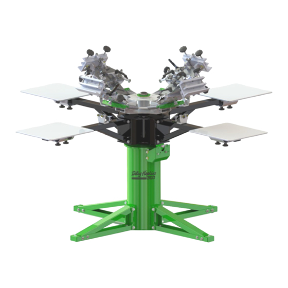
- Page 1 Assembly Instructions...
- Page 3 Tools Required: • Two 9/16” wrenches • Hammer What’ s in the box Item Qty. 1 per unit Main Press core assembly 1 per station 16” x 18” Aluminum platen with rubber top 1 per station Print station assembly 1 per station / Print station &...
- Page 4 PRSA-RHCLRARMKIT Riley Hopkins Print head bumper assembly Name/ID Description Qty. Air Hose for Riley print head bump stops 3-1/2” PRCO-BMPRBLTCVRBLU long PRHD-WA5/16USSGR5ZC 5/16 USS Flat Washer Zinc 3/8-24 x 4-1/2” Hex Cap Screw grade 5 Zinc PRHD-HC3/8NF4-1/2GR5ZC PRHD-LNYN3/8NFGR5ZC 3/8-24 Lowpro Nyloc Nut...
- Page 5 PRSA-RHPSKIT Riley Hopkins WIN series Print station Hardware Name/ID Description Qty. PRHD-HC3/8NC1GR5ZC 3/8-16 X 1 Hex Cap Screw Grade 5 Zinc PRHD-NYN3/8NCGR5ZC 3/8-16 Nyloc Nut Zinc PRHD-WA5/16USSGR5ZC 5/16 USS Flat Washer Zinc PRHD-RP3/16X1ZC 3/16 x 1 Roll Pin Zinc...
- Page 6 STEP 1 Install the lower bumper bolt assemblies. Do not overtighten hardware. Tighten just enough to hold in place. NOTE: Refer to page 2 for hardware detail Before dropping the print heads, ensure that spring hooks are engaged in the slots. The hooks must be facing upward. WARNING: EXTREME FORCE. INSTALL WITH CAUTION!
- Page 7 STEP 2 Install the Upper bumper bolt assemblies. No not overtighten hardware. Tighten just enough to hold in place. NOTE: Refer to page 2 for hardware detail...
- Page 8 STEP 3 Install the print stations with supplied hardware. Ensure the number on the print station matches the number on the center rotary. Failure to due so, will shift the platens out of alignment. Do not fully tighten at this time. They must be snug but loose enough to adjust with bumps of the hand.
- Page 9 STEP 4 Install the 3/16” roll pins to locate the print station. Tap print station to align holes visually as close as you can. This is a factory setting that ensures your platens are aligned to each other. Tap them in approx. ½” with a hammer.
- Page 10 STEP 5 Install the platens onto the print stations. Set the platen (1) in the desired position. To lock in place, first tighten the side knob (2). Then tighten the lower knobs (3).
- Page 11 STEP 6 Install leveling feet and optional adjustments For uneven floors, install leveling feet (1) & adjust to stabilize the unit. To increase or decrease tension on the print station detent bracket, loosen 3/8” bolts (2). Raise detent assembly for higher tension and lower assembly for less tension.
- Page 12 STEP 7 Setting the press in High position. To set up the overall press height plus 2 inches, first remove the hardware in the front of the leg assembly. Swivel leg sections downward to align with the rear set of holes. Repeat this step for the remaining three leg assemblies.
- Page 13 STEP 8 Bearing gate adjustment. To adjust the locking tightness of the bearing gate assembly, first slightly loosen the 5/16” hardware (3) on the set screw side of the gate. To tighten the gate, turn set screw clockwise toward the stud holding bearings.
- Page 14 STEP 9 Level the screen clamping heads to the pallets. This one-time setting will work for the vast majority of printing jobs. Future adjustment may be required to accommodate “custom” platens that are much higher than standard. Image Key: 1. Ensure the print head arm is level with the print station. 2.
- Page 15 STEP 10 (X/Y Micro adjustments) Before adjusting registration in the print head you must first loosen the micro lock-down levers (2). To adjust front-to-back use the turnbuckle knobs on the sides of the print head assembly (1). To adjust registration side-to-side, use the long knob on the side of the assembly (4).
- Page 16 STEP 11 Tilt/Off-Contact Micro adjustments Before adjusting off-contact (4) you must first loosen the off-contact jam knob (5). Once the desired off-contact is set, retighten the jam knob to hold in place. Before adjusting the tilt micro (1) you must loosen the tilt jam knob (2). Slowly loosen the tilt locking lever (3).
- Page 17 PRSA-RH300PNTHD Riley 300 Print head Sub assembly Name / ID Description Qty. Fluted CLAMP KNOBS 3/8-16 x 4” Male Stud PRCO-KNBFLT3/8NC4ML 4-prong thru-hole knob 3/8-24 Female PRCO-KNB4PRG3/8NFFM PRCO-KNBRCHT3/8NCFM 3/8 -16 Inch Course Ratchet Handles PRCO-BRNZB3/8ID1/2LG SINTERED BRZ BUSHING (SBB FL38 08) PRCO-RDED5/16LHML 5/16”-24 LEFT HAND THREAD MALE ROD ENDS PRCO-KNBTNBKL5/16NF...
- Page 18 While we take pride in our quality and do our best to ensure your satisfaction, Riley Hopkins™/Ryonet ® does not assume any liability for damages, whether consequential or incidental, that may result from the misuse of below stated specifications. LIMITED WARRANTY GENERAL PROVISIONS: The warranties described below apply ONLY to the original purchasers of new Riley Hopkins™...
- Page 19 1-800-314-6390 Ryonet Corporation | 12303 NE 56th St | Vancouver, WA 98682 | 1-800-314-6390 Page 2 ® NOTE: Logos, graphic elements and or photo images contained in this document may not be reproduced without the written consent of Ryonet...
Need help?
Do you have a question about the Riley Hopkins 300 and is the answer not in the manual?
Questions and answers