Table of Contents
Advertisement
Quick Links
AMAROK
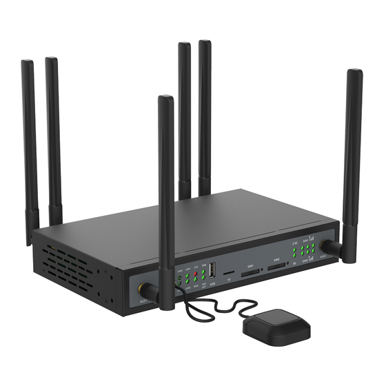
GL-X1200 is a 3G/4G wireless router with high-performance and stability, to meet with the requirements
of wireless network connection for industrial users. Based on OpenWRT OS, it also offered an integrated
platform of functions extension for developers, Makers, IoT integration and development.
GL-X1200 User Manual
1
Advertisement
Table of Contents

Subscribe to Our Youtube Channel
Related Manuals for GL-INET Amarok GL-X1200


Summary of Contents for GL-INET Amarok GL-X1200
- Page 1 AMAROK GL-X1200 is a 3G/4G wireless router with high-performance and stability, to meet with the requirements of wireless network connection for industrial users. Based on OpenWRT OS, it also offered an integrated platform of functions extension for developers, Makers, IoT integration and development. GL-X1200 User Manual...
- Page 2 Copyright © 2019 Shenzhen Guanglianzhitong Tech Co., Ltd. All rights reserved. Document Copyrights No duplication or distribution of this document or any portion thereof shall take place without the express written permission of Shenzhen Guanglianzhitong Tech Co., Ltd. No part of this manual may be reproduced, distributed, or transmitted in any form or by any means, electronic or mechanical, for any purpose without the express written permission of Shenzhen Guanglianzhitong Tech Co., Ltd.
- Page 3 (Including but not limited to software and technical data in products) mentioned in this manual. Contact Shenzhen Guanglianzhitong Tech. Co., Ltd Room 305-306, Skyworth Digital, Songbai road, Shiyan Street, Baoan District, Shenzhen, China Email:sales@gl-inet.com Tel: +86-755-86606126 Website: www.gl-inet.com...
-
Page 4: Table Of Contents
Catalogue Chapter 1 General Product Introduction ...................... 7 1.1 Brief Product Introduction........................7 1.2 Technical Specifications ..........................9 1.3 Appearance and dimension ........................11 1.4 Package list .............................. 12 1.5 Optional Configuration ........................... 15 Chapter 2 Hardware installation ........................16 2.1 LED light indicator ........................... - Page 5 4.1.4 Repeater ............................31 4.1.5 Tethering ............................35 4.1.6 3G/4G Modem ..........................36 4.2 Wireless ..............................42 4.2.1 2.4G & 5G WiFi ..........................43 4.2.2 2.4G & 5G Guest WiFi ........................44 4.3 Client ............................... 46 4.4.1 Online Upgrade ..........................48 4.4.2 Local Upgrade ..........................
- Page 6 5.2 Commands introduction ......................... 85 5.2.2 ping command ..........................86 5.2.3 nslookup commmand ........................87 5.2.4 traceroute command ........................88 5.2.5 iwinfo command ..........................89 5.2.9 iptables command ........................... 95...
-
Page 7: Chapter 1 General Product Introduction
Chapter 1 General Product Introduction 1.1 Brief Product Introduction GL-X1200 is an industrial grade wireless router which offers a solution for 4G network connection with cable or wirelessly. It is equipped with high-performance QCA9563, @775MHz SoC, with dual 4G/3G/2G modules as well as dual SIM card slots. - Page 8 Built-in RTC module Support RS232 or RS485 serial port (RJ45 port type). Powered by 12V or 48V DC power supply, or with POE power input (802.3at). Support 802.3af POE-Out (using 48V DC power in). Automatically shifting between wireless 4G connection and Ethernet cable connection to keep devices always ...
-
Page 9: Technical Specifications
1.2 Technical Specifications Items Description Model No. GL-X1200 Qualcomm QCA9563,@755MHz WiFi Chipset Qualcomm QCA9563 (2.4G) + Qualcomm QCA9886 (5G) Flash 16MB Nor-FLASH 128MB NAND-FLASH 128MB DDR 3G/4G module Support 2x 4G LTE CAT4 or CAT6) 2x micro SIM(3FF) card slot, e-SIM is optional 4G antenna External full-band antenna (700M ~ 2.7GHz) WiFi... - Page 10 MicroSD 1x MicroSD (TF) Slot, support maximum 128GB LED Indicator Power, PoE output, System, WAN, LAN, 2.4G Wi-Fi, 5G Wi-Fi, 4G Modem #1 signal strength、4G Modem #2 signal strength (Each 4G module has 3 LED indicate the signal strength) Reset Button Press the button more than 8 seconds to reset the device to factory settings.
-
Page 11: Appearance And Dimension
1.3 Appearance and dimension Dimension:240*145*40mm(L*W*H,External Antenna not included) Front view: Back view:... -
Page 12: Package List
1.4 Package list Items X1200 Dual-band WIFI antenna 4G antenna 4 or 2 (If selectCAT6module, it needs 4x External 4G antenna; If select CAT4 module, it needs 2x External 4G antennas) GPS antenna Power adapter Ethernet cable 35mm DIN rail Rack ear User guide •... - Page 13 • GPS antenna • Power adapter This picture is for 48V/1A power adapter, 12V/3A power adapter is optional. • Ethernet cable • 35mm DIN rail buckle...
- Page 14 • Rack Ears (Optional component) • Quick-start guide Product quick installation guide, including the download links to other documents or tools. Note:If the items above are missing or damaged, please feel free to contact sales@gl-inet.com...
-
Page 15: Optional Configuration
1.5 Optional Configuration • X1200-D2 4G module: 2 units Note: 2 * 4G modules are equipped before shipment. 2 *SIM card slots match 2 * 4G modules respectively • X1200-D1 4G module: 1 unit Note: 1 * 4G module is equipped before shipment, user could add one more 4G module in necessary. 2 * SIM card slots match 2* 4G modules respectively. -
Page 16: Chapter 2 Hardware Installation
Chapter 2 Hardware installation 2.1 LED light indicator Item Mark Color Description Power Green Off: Powered off On: Powered on PoE output PoE OUT Green Off: No PoE output On: LAN4 port provides PoE output System Off: System is running normally. Blinking: Operation System fault (E.g. -
Page 17: Reset Button
2.2 Reset button • Press and hold the reset button 8 seconds with a needle after powered on. • The device will be restarted, and reset to factory settings. 2.3 USB port • USB2.0 Type-A port. • Output voltage/current: 5V/500mA. 2.4 Micro-SD card slot •... -
Page 18: Sim Card Slot
2.5 SIM card slot Insert or remove SIM card • Press the button which next to the SIM card slot with a needle to pop up the SIM card tray. • Insert or remove the SIM card. • Standard size of SIM card should be 25*15mm. •... -
Page 19: Install Antennas
2.6 Install antennas Install 4G antennas. • SMA type (inner needle), full-band antenna, support 700MHz to 2.7GHz. • Install external 4G antenna on the 4G antenna interface and tighten it. • MAIN1 and AUX1 antennas (marked red in above picture) match 4G module 1. MAIN2 and AUX2 antennas (marked deepred in above picture) match 4G module 2. -
Page 20: Wall Mounting
• Adjust the position of device and ensure that the left and right sides have a more than 20mm space to radiate heat. 2.7.2 Wall Mounting Steps as below: • Install two fixing screws on the load plane (wall or cabinet). •... -
Page 21: Din-Rail Mounting
2.7.3 DIN-Rail Mounting Steps as below: • Fix the 35mm rail buckle on the bottom of device by using 4pcs M3*5mm countersunk screws. • Then install the device on the 35mm DIN rail. Note: • Select standard DIN rail bracket. -
Page 22: Cabinet Installation
2.7.4 Cabinet Installation Steps as below: • Fix the two Rack Ears on the two sides of the device by using 8pcs M3*5mm countersunk screws. • Then install the device on the 19’ standard cabinet. Note: • The Rack Ears and screws are optional accessories, please contact with our sales team. -
Page 23: Ground Wire Installation
2.8 Ground wire installation • Ground wire of the device helps prevent the effects of electromagnetic interference. • Connect the device with ground wire before powering on. • Remark: Ground wire should be installed on the well-grounded surface such as metal plates. 2.9 Console port connection •... -
Page 24: Ethernet Cable Connection
2.10 Ethernet cable connection • There are 1 WAN port and 4 LAN ports of the device. • WAN port is connected to the main router or modem, LAN port is connected to LAN devices. • Plug the Ethernet cable to LAN port and PC by using the Ethernet cable in accessory box. 2.11 Power Supply connection The device could be powered in 2 methods. -
Page 25: Powered By Poe Ethernet Cable
2.11.2 Powered by PoE Ethernet cable • WAN port supports POE power supply • Support 802.3at standard protocol, max receiving power is 25.5W. Note: • Please use standard PoE power-supply equipment to avoid insufficient or instable power supply. 2.11.3 POE output •... -
Page 26: Chapter 3 Login Web Ui
Chapter 3 Login Web UI 3.1 Login Connect PC to device LAN port and it will get IP address automatically assigned by the device. Input IP adress(Factory default IP address is 192.168.8.1) into browser, then it will show as follow. 3.2 Language Setting Select the Web language, you can choose Chinese, English and other languages, click Next to access the administrator password setting interface:... -
Page 27: Set Admin Password
3.3 Set Admin Password Set the admin password, showing as below: 3.4 Admin Panel Enter and submit the admin password, then access to the main page of the device, showing as below:... -
Page 28: Chapter 4 Device Configuration
Chapter 4 Device Configuration 4.1 Network... -
Page 29: Brief Introduction
4.1.1 Brief introduction 1: Menu bar 2: Cable 3: Repeater 4: Tethering 5: 34/4G Modem 6: Status display bar 7: Click GL-iNet to jump to GL-iNet official website 8: Restart/logout/language selection... -
Page 30: Status
4.1.2 Status 1. Networking status Cable, Repeater, Tethering, 3G/4G Modem networking. Gray indicates no connection. Highlighting indicates successful connection. 2. VPN connection status . Wireless SSID status 2.4G/5G SSID/ Guest SSID are displayed, gray indicates disable, and highlighted indicates enable. 4. -
Page 31: Repeater
Click ‘modify’ to change the way of network connection, DHCP/Static/PPPOE as below: 4.1.4 Repeater Before setting, it will show as below: Scan: Scan the surrounding hot spots Existing network: It will save wireless hot spots connected previously Repeater Options: Turn on or off its auto connection function... - Page 32 4.1.4.1 Scan Click‘Scan’and it will show as below: Finish scan it will show as below: Click drop-down arrow to choose SSID, showing as below:...
- Page 33 Choose the SSID, input password, turn on network saving function, then add, showing as below: After successful connection it will pop-up as below: Wait 5s,it will enter into admin panel. Status bar will show the SSID connected, showing as below:...
- Page 34 SSID, IP address, subnet mask, gateway, DNS server will be displayed. 4.1.4.2 Existing Network Click existing network, it will display the list as below: Click SSID, user can click forget or add to re-connect this SSID, showing as below:...
-
Page 35: Tethering
4.1.4.3 Repeater Options Click ‘Repeater options’, it will pop-up below page. User can turn on or off the function of auto scan and connection. Auto scan and connection: It enables auto switching to available SSID. 4.1.5 Tethering Disconnection will display as below: Use original USB cable to connect phone and the device, then turn on USB network sharing of the phone, showing as below:... -
Page 36: 4G Modem
It will display as below after successful connection: 4.1.6 3G/4G Modem Before 4G module setting, it will show as below: Click ‘Auto setting’, after successful connection it will show as below:... - Page 37 4.1.6.1 Manual Setting Click ‘Manual setting’ to choose dialing device and APN, showing as below: Click ‘More’ to get more setting options as follows:...
- Page 38 4.1.6.2 AT command Click ‘AT command’ and enter into interface as follows:...
- Page 39 Click on the drop-down menu to display the packaged instructions as follows: Select Request IMEI and click send, successfully read as follows:...
- Page 40 4.1.6.3 Reset Module Clicking ‘Reset module’ to proceed reset. It will take about 25s, showing as below: 4.1.6.4 Community Information Click ‘Community information’ to view the modem community information. It supports copy and refresh functions, showing as below: 4.1.6.5 Single Module with Dual SIM Card If the product is single 4G module with dual SIM card (limited to product type ‘X1200-S’), this function supports switching SIM cards as follows:...
- Page 41 Click the drop-down arrow to switch SIM card as follows: Note: Modem2 has the same setting way as Modem1. Two modems could be applied at the same time to offer network connection.
-
Page 42: Wireless
4.2 Wireless Click ‘Wireless’ to enter into Wi-Fi management interface as follows:... -
Page 43: G & 5G Wifi
4.2.1 2.4G & 5G WiFi Click ‘Wireless’ and enter into 2.4G/5G Wi-Fi management interface in default as follows:... -
Page 44: G & 5G Guest Wifi
Wireless Network Name (SSID): Wireless SSID Wireless network security: wireless encryption method Wireless network password: wireless password SSID visibility: whether to hide the SSID or not Channel: channel settings Rate: Rate settings Transmit power: transmit power settings 4.2.2 2.4G & 5G Guest WiFi Click ‘2.4G Guest WiFi’... - Page 45 Guest WiFi is turned off in default. Modification of wireless network name, wireless network security, and wireless network password is supportable.
-
Page 46: Client
4.3 Client Click ‘Client’ and it will display the turn-off of traffic statistics as below: Turn on traffic statistics which supports QoS as follows:... - Page 47 Click "Settings" to QOS settings page. Upload and download rate can be limited, showing as below The speed limit value can be checked. Click Reset to cancel speed limit, showing as below: Note: It is not recommended to keep traffic statistics on as it will increase CPU load.
-
Page 48: Online Upgrade
4.4 Upgrade Click ‘Upgrade’,showing as below: 4.4.1 Online Upgrade Click ‘Upgrade’, then enter into online upgrade interface in default, showing as below: Current Version: Current firmware version Compile Time: Firmware compilation time Latest Update: The latest firmware version of the server. Only if the current software version is lower than the server firmware version then it will indicate ‘Upgrade’, showing as below:... -
Page 49: Local Upgrade
Click ‘Download’ to get the firmware, it will show as below when complete: Configuration upgrade is kept in default. Click ‘Install’ to start updating firmware. Please do not cut off power during the process, otherwise the device is unable to start. 4.4.2 Local Upgrade Click ‘Local Upgrade’, enter into local upgrade interface, showing as below:... -
Page 50: Automatic Upgrade
Click to select a file to upload or drag it to this location. After uploading, click "Install" to start updating firmware. Upgrade process is the same as online upgrade. 4.4.3 Automatic Upgrade Click ‘Automatic upgrade’, then access to the interface, showing as below: Upgrade time is optional and upgrade could be executed in definite time. -
Page 51: Firewall
Notes: Automatic upgrade requires a higher version of the server than local device version. 4.5 Firewall Click ‘Firewall’, showing as below: 4.5.1 Port Forwarding then Click ‘Firewall’, access to port forwarding interface in default, showing as below: Name: The rule name Internal IP: IP address assigned by LAN device... -
Page 52: Turn On Ports
External Ports: Support to input a range Internal Ports: The listening port of LAN device Protocols: TCP, UDP, TCP/UDP Status: Rule status, supports enable and disable Operation: Add the rules set currently Following operations are supportable: Add: Add rules set currently Modify: Modify the rules Delete: Delete the current rules Delete All: Delete All Rules... - Page 53 Name: The rule Name Port: Router ports to be turn on Protocols: TCP, UDP, TCP/UDP Status: Rule status, supports enable and disable Operation: Add the rules set currently Following operations are supportable: Add: Add rules set currently Modify: Modify the rules Delete: Delete the current rules...
-
Page 54: Dmz
Delete All: Delete All Rules 4.5.3 DMZ then enter into Click ‘DMZ’, DMZ setup interface, showing as below: Turn on DMZ: The switch is turned off in default DMZ host IP: Support manual input and select existing IP, just click the drop-down arrow Turn on DMZ, showing as below: Turn on the switch, input or select the DMZ host IP, then click on application. -
Page 55: Vpn(No Chinese Version
4.6 VPN(No Chinese Version) 4.6.1 OpenVPN Client Click ‘OpenVPN Client’ under VPN menu, showing as below: For instructions, please refer to the following link to the OpenVPN Client chapter https://docs.gl-inet.com/en/3/app/openvpn/ 4.6.2 OpenVPN Server Click ‘OpenVPN Server’ under VPN menu, showing as below:... -
Page 56: Wireguard Client
For instructions, please refer to the following link to the OpenVPN Server chapter https://docs.gl-inet.com/en/3/app/openvpn/ 4.6.3 Wireguard Client Click ‘Wireguard Client’ under VPN menu, showing as below: For instructions, please refer to the following link to the Wireguard Client chapter https://docs.gl-inet.com/en/3/app/wireguard/... -
Page 57: Wireguard Server
4.6.4 Wireguard Server Click ‘Wireguard Server’ under VPN menu, showing as below: For instructions, please refer to the following link to the Wireguard Servers chapter https://docs.gl-inet.com/en/3/app/wireguard/ 4.6.5 VPN Policies Click ‘Wireguard Policies’ under VPN menu, showing as below:... -
Page 58: Application Program
For instructions, please refer to the following link to the Wireguard Policies chapter https://docs.gl-inet.com/en/3/app/vpn_policies/ 4.7 Application Program 4.7.1 SDK Click ‘application program’, select SDK, showing as below:... - Page 59 Upgrade: Upgrade the package to get a list of software for routing support Filter: Support software package filter and keyword search. Free space: It means the remaining space of Flash. When the space is less than 5%, no more installation of software packages, otherwise the system may get failure.
-
Page 60: File Sharing
Writable: USB flash disk and SD card is not writable in default. This function should be used carefully, it is easy to write the USB flash disk disabled. Please refer to the following link for detailed usage: https://docs.gl-inet.com/en/3/app/file_sharing/ 4.7.3 Remote Access Click ‘More settings’, then select Remote Access to enter managing interface, showing as below:... - Page 61 Detailed usage of cloud management, please refer to below link https://docs.gl-inet.com/en/3/app/cloud/ Dynamic DNS function, please refer to below link https://docs.gl-inet.com/en/3/app/ddns/...
-
Page 62: Captive Portal
4.7.4 Captive Portal Click ‘application program’, then select ‘Captive Portal’ to enter into Management interface, showing as below: Detailed usage, please refer to below link, https://docs.gl-inet.com/en/3/app/captive_portal/ 4.8 More Settings 4.8.1 Admin Password Click ‘More Settings’, then click ‘Admin Password’ and enter into setting interface, showing as below:... -
Page 63: Lan Ip
Old password: Please input old admin password. New password: Please input new admin password Confirm password: Please re-input new admin password. 4.8.2 LAN IP Click ‘More Settings’, then select LAN IP and enter into Setting interface, showing as below:... - Page 64 LAN IP: Set router LAN IP address Guest IP: Set router guest network IP address Static IP address binding: Static binding means IP bind with MAC address.
- Page 65 4.8.2.1 LAN IP Click ‘More Settings’, then select LAN IP and enter into Setting interface, showing as below: LAN IP: IP address of the router gateway Starting IP address: DHCP server assigns starting IP address Ending IP address: DHCP server assigns ending address Note: Starting IP address need to be smaller than ending IP address.
- Page 66 Guest IP: IP address of router’s guest network Starting IP address: DHCP server assigns starting IP address Ending IP address: DHCP server assigns ending IP address Note: Starting IP address need smaller than ending IP address. 4.8.2.3 Static IP address binding Static IP address binding can bind IP with MAC address, showing as below,...
- Page 67 MAC: Client MAC list, support manual input or drop-down list selection IP: IP address assigned to the client can be manually entered or selected from the drop-down list Operation: Add the binding rules set currently Select Mac address and IP address, then click to add, showing as below:...
- Page 68 Note: Static binding requires client to retrieve IP.
-
Page 69: Time Zone
4.8.3 Time Zone Click “more setting”, then click “time zone” to enter into setting page, showing as below: Time Zone: Time zone and time setting, time zone is optional Sync: Synchronize Browser time Time Sync: NTP Client and NTP server settings NTP Client: NTP Client switch, on and off is optional NTP Server: NTP server switch, on and off is optional NTP Server address: 1/2/3/4: can input NTP Server address 1/2/3/4... -
Page 70: Gps
4.8.4 GPS Click “more setting”, then click “GPS” to enter into setting page, showing as below: Device MAC: Device WAN MAC address Status: Whether Current orientation is valid UTC time: UTC time Latitude: Latitude Longitude: Longitude Data reporting: The GPS data reporting switch is off by default. - Page 71 GPS locate to data, showing as below: Enable data reporting function, showing as below:...
- Page 72 Enable to set reporting address and reporting circle...
-
Page 73: Mac Address Clone
4.8.5 MAC address Clone Click “more setting”, then click “MAC address clone” to enter into setting page, showing as below: Current Client: current client MAC address Factory Default: Factory default WAN port MAC address Your device (WAN): Current device WAN MAC Address Click your device to choose clone MAC address, showing as below:... -
Page 74: Self-Defined Dns Server
It is optional to choose clone client MAC or generate MAC randomly 4.8.6 Self-defined DNS server Click ‘more setting’, then click “Self-defined DNS server”, showing as below: DNS re-binding attack protection: on/off is optional, default on DNS settings for All Clients: on/off is optional, default off DNS over TLS of Cloud flare: on/off is optional, default off Manual DNS server setting: on/off is optional, default off... -
Page 75: Network Mode
Note: Cloud flare and manual DNS conflicts, either-or 4.8.7 Network mode Click “more setting”, then click “Network mode” to enter into setting page, showing as below:... -
Page 76: Reset To Factory Setting
Routing mode: The device connect to upper device by WAN Port, repeater, tethering or modem. AP mode: The device connect to upper device by WAN Port. Wireless extender mode: This device will be used as a repeater connects to the main router via wireless, it works on layer 3 in OSI model, and all its LAN devices will acquire IP address from the main router. -
Page 77: Advanced Functions
Note: Reset to factory setting will clear all the settings of the device, be cautious. 4.8.9 Advanced functions Click ‘More settings’, then click ‘advanced function’ to enter into Luci management page, showing as below:... - Page 78 Default username is root, and password is admin password. Input and click ‘Login’ to enter into advanced page, showing as below:...
- Page 79 Chapter 5 Commands Introduction 5.1 Login by SSH 5.1.1 Download and install PuTTY Download link as following: https://www.chiark.greenend.org.uk/~sgtatham/putty/latest.html Install PuTTY...
-
Page 82: Login By Putty
5.1.2 Login by PuTTY Follow below steps to open PuTTY:... - Page 83 Set PuTTY. Default IP address is 192.168.8.1, default port is 22, and choose the connecting type SSH as below: Click Open to pop up the interface as below, choose "Yes" Enter default user name ‘root’, the password is the administrator password you set, as below:...
- Page 84 After log in, the interface displays as below:...
- Page 85 5.2 Commands introduction 5.2.1 ifconfig command ifconfig command can check the basic status of network ports, steps asbelow: Example of ifconfig command:...
- Page 86 5.2.2 ping command ping command can check whether the network is normal Example of ping command:...
- Page 87 5.2.3 nslookup commmand nslookup command can query IP according to domain name, and judge whether the DNS for current device is normal,steps as below: Example of nslookup command:...
- Page 88 5.2.4 traceroute command tracerouter command can trace the path of accessing address, steps as below Example of tracerouter command:...
- Page 89 5.2.5 iwinfo command iwinfo command is wireless related command, steps as below: Example of iwinfo command: Check basic information of network port...
- Page 90 Scan surrounding hot spots...
- Page 91 5.2.6 uci command uci command can check, modify and set configuration, steps as below:...
- Page 92 Example of uci command, checking network configuration:...
- Page 93 5.2.7 route command Route command can manage routing table, steps as below Example of route command:...
- Page 94 5.2.8 mwan3 command mwan3 command is responsible for network priority switching, steps as below: Example of mwan3 command:...
- Page 95 5.2.9 iptables command iptables command is firewall-related, steps as below:...
- Page 96 Example of iptables command:...
Need help?
Do you have a question about the Amarok GL-X1200 and is the answer not in the manual?
Questions and answers