
Related Manuals for Pentair Fleck 3200NT


Summary of Contents for Pentair Fleck 3200NT
- Page 1 3200NT Service Manual IMPORTANT: Fill in Pertinent Information on Page 3 for Future Reference...
-
Page 2: Table Of Contents
Table of Contents Job Specification Sheet............................3 Timer Operation..............................4 Master Programming Mode Flow Chart....................... 10 Master Programming Mode..........................14 Operation Display Definitions & Examples......................20 Diagnostic Programming Mode Flow Chart......................21 Diagnostic Programming Guide........................... 22 Diagnostics Display Definitions &... -
Page 3: Job Specification Sheet
Job Specification Sheet Please Circle and/or Fill in the Appropriate Data for Future Reference: Programming Mode: Feed Water Hardness: _____________ Grains per Gallon or Degrees Regeneration Time: Delayed __________ AM/PM or Immediate Regeneration Day Override: Off or Every _____ Days Master Programming Mode: Valve Type: 2750 / 2850 / 2900s / 3150 / 3900... -
Page 4: Timer Operation
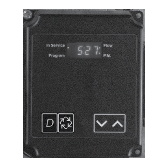
Timer Operation Set Time of Day When the timer is In Service, push either the Set Up or Set Down button once to adjust the Time of Day by one digit. Push and hold to adjust by several digits. Manually Initiating a Regeneration 1. - Page 5 Timer Operation Immediate Regeneration Timer with Regeneration Day Override Set When the valve reaches the set Days Since Regeneration Override value, a Regeneration Cycle initiates immedi- ately. This occurs even if the Volume Remaining display has not reached zero. Delayed Regeneration Timer with Regeneration Day Override Set When the timer reaches the set Days Since Regeneration Override value a Regeneration Cycle initiates at the preset Regeneration Time.
- Page 6 Timer Operation System 4 Time Clock (1 Valve) During normal operation the Time of Day display may be viewed at all times. The control operates normally until the number of days since the last regeneration reaches the Regeneration Day Override setting. Once this occurs, a Regeneration Cycle initiates at the preset Regeneration Time.
- Page 7 Timer Operation System 7 Alternating (2 Valves) During normal operation the Time of Day display alternates with the Volume Remaining display (gallons or m3). The Volume Remaining is for the individual unit. — As treated water is used, the Volume Remaining display counts down from the calculated capacity to zero or (----).
- Page 8 Timer Operation 1. Enter 3200NT Programming Mode Press and hold both the Set Up and Set Down buttons for five (5) seconds to enter Programming Mode. When the program mode is entered, the program light illuminates. 2. Set Feed Water Hardness The feed water hardness setting displays only if the Regenera- tion Type is set to Meter Immediate or Meter Delayed.
- Page 9 Timer Operation 3. Set Regeneration Time A non-flashing colon between two sets of numbers identifies the Regeneration Time display. Set the desired time of day that you want Regeneration to occur. — Press the Set Up and Set Down buttons to adjust this value.
-
Page 10: Master Programming Mode Flow Chart
Master Programming Mode Flow Chart NOTE: 1. Set Time of Day Display to 12:01 P.M. 2. Press and hold both the Set Up and Set Down buttons for 5 seconds. 3. Press the Extra Cycle button once per display until all displays are viewed and Normal Display is resumed. - Page 11 Master Programming Mode Flow Chart CAUTION: Before entering Master Programming, please contact your local professional water dealer. Page 11...
- Page 12 Master Programming Mode Flow Chart CAUTION: Before entering Master Programming, please contact your local professional water dealer. Page 12...
- Page 13 Master Programming Mode Flow Chart CAUTION: Before entering Master Programming, please contact your local professional water dealer. Page 13...
-
Page 14: Master Programming Mode
Master Programming Mode When the Master Programming Mode is entered, all available option setting displays may be viewed and set as needed. Depending on current option settings, some displays cannot be viewed or set. Entering Master Programming Mode Set the Time Of Day display to 12:01 P.M. Press and hold the Set Up and Set Down buttons together until the Program indicator turns on (about 5 seconds). - Page 15 Master Programming Mode 3. System Type Use this program step to set the System Type. Possible settings are: System Type 4 Time Clock Delayed Setting: [ 4tc ] The control regenerates on the days set in Regeneration Day Override, at the Regeneration Time set in Regeneration Time.
- Page 16 Master Programming Mode 5. Remote Signal Start (Display Code rS) The control valve is monitored other than a meter. Regeneration begins immediately after a contact closure is received for the number of minutes programmed. The amount of time is required for a contact closure to be presented before the signal is considered to be valid.
- Page 17 Master Programming Mode 9. Feed Water Hardness (Display Code H) This program step sets the feed water hardness. The letter H in the first digit of the display identifies this program step. The system automatically calculates treated water capacity based on the feed water hardness entered in this program step and the system capacity entered in program step #3.
- Page 18 Master Programming Mode 13. Auxiliary Relay Output (Display Codes AroF, cPoF) The next two displays viewed are part of a series of settings used to program the optional relay output. The first setting turns the output on / off during Regeneration only. The second turns the output on during Service only, when a set volume of water used has accumulated.
- Page 19 Master Programming Mode 15. Generic Flow Meter Size (Display Code F) This program step sets the proper number of pulses generated by the flow meter for each gallon or liter of water flow. Range = 0.1 – 99.9 pulses per gallon 100 –...
-
Page 20: Operation Display Definitions & Examples
Operation Display Definitions & Examples Time of Day Calculating the Volume Remaining Format = US/Gallons Communication Error Format = Metric/Meter Volume Remaining L = Display Code (X 1,000,000) Programming Error Range = 1,000,000 - 2,900,000 t = Display Code (X 1000) Range = 10,000 - 999,999 Timer is Locked Out No Display Code... -
Page 21: Diagnostic Programming Mode Flow Chart
Diagnostic Programming Mode Flow Chart NOTE: 1. Push and release the “D” button. 2. Press the Extra Cycle button once per display until all displays are viewed and Normal Display is resumed. 3. Press and release the “D” button at anytime during diagnostic mode and the timer will exit the mode. -
Page 22: Diagnostic Programming Guide
Diagnostic Programming Guide When the Diagnostics Mode is entered, all available displays are viewed as needed. Depending on current option settings, some displays cannot be viewed. Overview Diagnostic Mode The current diagnostic will be displayed until Extra Cycle key is pressed. There is no time limit on each display. The timer will display local information, not system information. - Page 23 Diagnostic Programming Guide 3. Totalizer (Display Code t = x 1000, L = x 1,000,000) The total volume of treated water that passes through a meter will be counted to a maximum limit of 99,999,999 gallons or m3. Reset to zero by holding up and down keys for 5 seconds during the Totalizer display.
-
Page 24: Diagnostics Display Definitions & Examples
Diagnostics Display Definitions & Examples Flow Rate Hours Between Last Two Regenerations r = Display Code II = Display Code Range = 1 - 99.9 Range = 1 - 199 Hours Since Last Regeneration ≡ = Display Code Range = 1 - 199 Range = 100 - 500 Adjustable Volume Remaining L = Display Code (X 1,000,000) - Page 25 Notes Page 25...
-
Page 26: Power Head Assembly 2750/2850/2900 Upper Drive And 2900 Lower Drive & Parts List
Power Head Assembly 2750/2850/2900 Upper Drive and 2900 Lower Drive Page 26... - Page 27 Power Head Assembly Parts List 2750/2850/2900 Upper Drive and 2900 Lower Drive Item No. Quantity Part No. Description 1....1..... 41062.......3200NT Timer Assy 2....1..... 14202-01....Screw, Hex Wsh Mach, 8-32 x 5/16 3....1..... 40959.......Bracket, Strain Relief, 3200NT 4.
-
Page 28: Power Head Assembly 3150/3900 Upper Drive And 3900 Lower Drive & Parts List
Power Head Assembly 3150/3900 Upper Drive and 3900 Lower Drive Page 28... - Page 29 Power Head Assembly Parts List 3150/3900 Upper Drive and 3900 Lower Drive Item No. Quantity Part No. Description 1....1..... 41062.......3200NT Timer Assy 2....1..... 14202-01....Screw, Hex Wsh Mach, 8-32 x 5/16 3....1..... 40959.......Bracket, Strain Relief, 3200NT 4.
-
Page 30: 1" Brass Paddle Meter
1” Brass Paddle Meter Item No..Quantity ..Part No....Description 1....1..... 14959.......Body, Meter, 2750 2....1..... 13882.......Post, Meter Impeller 3....1..... 13509.......Impeller, Meter 4....1..... 13847.......O-ring, -137, Std/560CD, Meter 5. -
Page 31: 1" & 1 1/2" Plastic Turbine Meter
1” & 1 1/2” Plastic Turbine Meter Item No. Quantity Part No. Description 1....1..... 17542.......Flow Straightener, 1 1/2” 2....1..... 40576.......Clip, H, Plastic, 7000 3....1..... 40577.......Turbine Meter Assy, 7000 4....1..... 41555.......Body, Remote Meter 5. -
Page 32: 1/2" Brass Paddle Meter
1 1/2” Brass Paddle Meter Item No. Quantity Part No. Description 1....1..... 17569.......Body, Meter, 2850/9500 2....1..... 13882.......Post, Meter Impeller 3....1..... 13509.......Impeller, Meter 4....1..... 13847.......O-Ring, -137, Std/560CD, Meter 5....1..... 14716.......Meter Cap Assy, ET/NT 6. -
Page 33: 2" Brass Paddle Meter
2” Brass Paddle Meter Item No. Quantity Part No. Description 1....1..... 14456.......Body, Meter, 2” 2....1..... 14679.......O-ring, -227, Meter 3....1..... 14568.......Fitting, Nipple, 2” 4....1..... 14680.......Flow Straightener 5....1..... 14569.......Nut, 2900 Meter 6. -
Page 34: 2" Plastic Paddle Meter
2” Plastic Paddle Meter Item No. Quantity Part No. Description 1....1..... 17689....Body, Meter, 2” Plastic w/Impeller Shaft Seat 2....1..... 15532....Seat, Impeller Shaft, Hex 3....1..... 15432....Shaft, Impeller, SS 4....1..... 60620....Meter Assembly, 2” Plastic, Std 60621.... -
Page 35: 3" Brass Paddle Meter
3” Brass Paddle Meter Item No. Quantity Part No. Description 1....1..... 16254.......Body, Meter, 3900 2....1..... 16279.......Shaft, Impeller 3....1..... 16575.......Impeller Assy, 3” 4....1..... 14716-01....Meter Cap Assy, 3”, ET 5. -
Page 36: 2750/2850 Timer Wiring Diagram
2750/2850 Timer Wiring Diagram Page 36... -
Page 37: 3150 Timer Wiring Diagram
3150 Timer Wiring Diagram Page 37... -
Page 38: 2900 Timer Wiring Diagram
2900 Timer Wiring Diagram Page 38... -
Page 39: 3900 Timer Wiring Diagram
3900 Timer Wiring Diagram Page 39... -
Page 40: 3200Nt Remote Timer Wiring Diagram
3200NT Remote Timer Wiring Diagram 42073_REVA Page 40... -
Page 41: 2750/2850 - 3200Nt Remote Wiring Diagram
2750/2850 - 3200NT Remote Wiring Diagram 42074_REVA Page 41... -
Page 42: 3150 - 3200Nt Remote Wiring Diagram
3150 - 3200NT Remote Wiring Diagram 42076_REVA Page 42... -
Page 43: 2900 - 3200Nt Remote Wiring Diagram
2900 - 3200NT Remote Wiring Diagram 42075_REVA Page 43... -
Page 44: 3900 - 3200Nt Remote Wiring Diagram
3900 - 3200NT Remote Wiring Diagram 42077_REVA Page 44... -
Page 45: Network Timer System Configuration Wiring Diagrams
Network Timer System Configuration Wiring Diagrams Interlocking 3200NT NOTE: Use only 6-place, 4-conductor, RJ11 phone or extension cables. 1. Connect phone or extension cables first before programming. — System Type 7 and 6: flow meter cable must be connected to the timer programmed as the LEAd Timer. 2. -
Page 46: Transformer, Phone Cable And Meter Cable Installation
Transformer, Phone Cable and Meter Cable Installation Installing Ground Wire on Transformer (2750/2850/2900 Valves) Installing Ground Wire on Transformer (3150/3900 Valves) Installing and Grounding the Transformer 1. Locate the ground label to find ground screw. 2. Remove the screw and attach the transformer ground wire. 3. -
Page 47: Troubleshooting
Troubleshooting Communication Error If a communication error is detected, cErr displays. It may take several minutes for all of the units in a system to display the error message. — All units In Service remain in the In Service position. —... - Page 48 Troubleshooting Programming Error Timers display PErr when a programming error occurs. — If multiple timers are programmed as LEAd, PErr displays on all units. — If multiple timers are programmed with different system types, feed water hardness, regeneration day override and line frequency, a PErr will be displayed. —...
- Page 49 Notes Page 49...
- Page 50 Notes Page 50...
- Page 51 Notes Page 51...
- Page 52 P/N 41093 Rev. E 9/06...
Need help?
Do you have a question about the Fleck 3200NT and is the answer not in the manual?
Questions and answers