Table of Contents
Advertisement
Advertisement
Table of Contents

Related Manuals for Ferris ISX800Z Series


Summary of Contents for Ferris ISX800Z Series
-
Page 2: Table Of Contents
Table of Contents: Products Covered by This Manual........3 Identification Tag Location..........3 CE Identification Tag Markings........... 3 Operator Safety..............4 Operating Safely...............4 Slope Identification Guide..........6 Safety Rules and Information...........6 Safety Decals..............10 Safety Icons..............11 Safety Icons for Optional Jack Kit Accessory....12 Safety Alert Symbol and Signal Words...... -
Page 3: Products Covered By This Manual
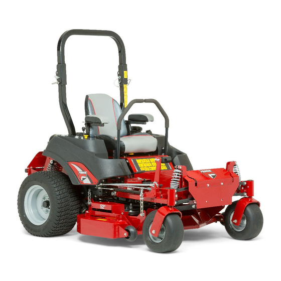
Thank you for purchasing this quality-built Ferris Commercial Unit Model Number: Zero Turn Mower. We’re pleased that you’ve placed Unit Serial Number: your confidence in the Ferris brand. When operated and Mower Deck Model Number: maintained according to the manuals, your Ferris product will (if applicable) ... -
Page 4: Operator Safety
Operator Safety included to help you get the most out of your equipment investment. Be sure to completely read the Safety Rules and Information Operating Safely found on the following pages. Also completely read the Read these safety rules and follow them closely. Failure to Operation section. ... - Page 5 Thrown Objects Keep the roll bar in the raised position and fasten the seat belt. There is no roll over protection when the roll bar is down! Do not jump off if the mower tips (it is safer to be secured by the seat belt with the roll bar raised.) Lower the roll bar only when necessary (such as to temporarily clear a low overhanging obstacle) and NEVER...
-
Page 6: Slope Identification Guide
Gasoline and its vapors are extremely flammable. Do not smoke while operating or refueling. Do not add fuel while WARNING engine is hot or running. Allow engine to cool for at least 3 Do not operate on slopes greater than 15 degrees. minutes prior to adding fuel. ... - Page 7 • Wear appropriate clothing including safety shoes, safety • Stop equipment and inspect blades after striking objects glasses and ear protection. Long hair, loose clothing or or abnormal vibration occurs. Make necessary repairs jewelry may get tangled in moving parts. before resuming operations. ...
- Page 8 may suddenly appear in the mowing area for another ride of the angle at which machine lift-off occurred in static tests. Actual dynamic stability may vary depending on operating conditions. and be run over or backed over by the machine. Do: ...
- Page 9 • Never store the machine or fuel container inside where there is an open flame, such as in a water heater. Allow WARNING unit to cool before storing. Units with hydraulic pumps, hoses, or motors: Hydraulic • Shut off fuel while storing or transporting. Do not store fluid escaping under pressure may have sufficient force to fuel near flames or drain indoors. ...
-
Page 10: Safety Decals
Inspection and Maintenance of the Roll Bar Inspection of the Roll Bar Protective Structure Seat Belt WARNING WARNING Failure to properly inspect and maintain the ROLL BAR Failure to properly inspect and maintain the seat belt can protective structure can cause serious injury or death. cause serious injury or death. ... -
Page 11: Safety Icons
F.) Battery Safety Decal G.) Part Number: 5100536 H.) Part Number: 5100685 I.) Part Number: 5100537 A.) Part Number: 84001877 Safety Icons B.) Part Number: 7106109 Warning: Read and understand the Operator’s Manual before using this machine. Know the location and function of all controls. -
Page 12: Safety Icons For Optional Jack Kit Accessory
Danger - Amputation hazard: Do Warning: Avoid Serious Injury or not mow when children or others are Death from Roll Over - Keep roll bar around. Never carry riders especially, in the raised position and use seat children even with the blades off. Do belt. -
Page 13: Safety Alert Symbol And Signal Words
Features and Controls machine and secure with jack stands before working under the machine. Control Functions and Locations Safety Alert Symbol and Signal Words The information below briefly describes the function of individual controls. Starting, stopping, driving, and mowing The safety alert symbol ( ) is used to identify safety require the combined use of several controls applied in information about hazards that can result in personal injury. - Page 14 Callout Icon Description FORWARD Cutting Height Adjustment Pin NEUTRAL Deck Lift Lock Lever REVERSE NEUTRAL LOCKOUT Parking Brake: Pull the parking brake lever up and POSITION back to engage the parking brake. Move the lever fully The parking brake must be disengaged before attempting to forward and down to disengage the parking brake.
-
Page 15: Instrument Control Panel
remove the retainer hardware and tilt the floor pan up and then remove from the machine. Reverse the process for re- PTO (Power Take Off) Switch: The PTO switch installation. engages and disengages the mower blades. Pull UP on the switch to engage, and push DOWN to disengage. -
Page 16: Operation
To begin recording engine hours, start the unit's engine and release the parking brake. The hour glass icon will flash. WARNING Do NOT load this zero-turn rider on a trailer or truck using To begin recording PTO hours, pull the PTO switch up to two separate ramps. -
Page 17: Stopping The Rider
5. After warming the engine always operate the unit at FULL throttle when mowing. In the event of an emergency the engine can be stopped by simply turning the ignition switch to STOP. Use this method only in emergency situations. For normal engine shut down follow the procedure given in Stopping the Rider. - Page 18 Reverse Travel Practice To turn in place, “Zero Turn,” gradually move one ground speed control lever forward from neutral and one lever back LOOK DOWN & BEHIND, then gradually move both ground from neutral simultaneously. Repeat several times. speed control levers evenly BACK from neutral. Slow down NOTE: Changing the amount each lever is pulled—forward or and repeat.
-
Page 19: Mowing
As you become more familiar and experienced with operating the Zero Turn rider, you will learn more maneuvers that will make your mowing time easier and more enjoyable. Remember, the more you practice, the better your control of the Zero Turn will be! Mowing 1. - Page 20 • Avoid mowing after rain or even heavy dew, and never The remainder of the mowing should be done in the opposite mulch when the grass is wet (moist grass does not mulch direction so that the clippings are dispersed OUT onto the well, and clumps beneath the mower deck).
-
Page 21: Pushing The Rider By Hand
The best mulching action typically results from cutting only the top ½ inch to 3/4 inch of grass blade. This provides Raise and Lower the Roll Bar short clippings which decompose properly (much more quickly than longer clippings). The ideal cutting height will vary with climate, time of year, and quality of your lawn. -
Page 22: Attaching A Trailer
3. Push or pull the top of the roll bar forward against the spring clips and reinstall the retainer pins and hair pin clips to secure the roll bar in the raised position. Attaching a Trailer The maximum weight of a towed trailer should be less than 200 lbs (91kg). -
Page 23: Purging The Air From The Hydraulic System
Oil Type: 20W-50 conventional detergent motor oil slowly move the zero-turn rider’s ground speed control levers in both forward and reverse directions (5 to 6 1. Locate the transmission oil tanks (A, Figure 23) by raising times), as air is purged from the unit, the oil level will the seat plate of the unit. -
Page 24: Ground Speed Control Lever Adjustment
Ground Speed Control Lever Adjustment The control levers can be adjusted in three ways. The alignment of the control levers, the placement of the levers (how close the ends are to one another) and the height of the levers can be adjusted. To Adjust the Handle Alignment Loosen the mount bolts (A, Figure 25) and pivot the lever(s) (C) to align with each other. -
Page 25: Suspension Adjustment
1. Remove the foot pedal (A, Figure 27) from the pedal mount tab (B). 2. Remove the pedal mount hardware (C) and rotate the tab 180 degrees. 3. Reinstall the pedal mount hardware and tighten securely. 4. Reinstall the foot pedal on the pedal mount tab in the proper orientation as shown in Figure 27. -
Page 26: Storage
To Adjust the Spring Pre-Load: Remember, the fuel tank will still contain some gasoline, so never store the unit indoors or in any other area where fuel This procedure details the process for adjusting the spring vapor could travel to any ignition source. Fuel vapor is also pre-load of the rear shocks. -
Page 27: Maintenance Schedule
once a month. If battery is left in unit, disconnect the UNIT MAINTENANCE negative cable. Every 100 Hours 10. Drain fuel system completely or add a gasoline stabilizer Check Mower Blade Stopping Time to the fuel system. If you have chosen to use a fuel Clean Battery &... -
Page 28: Warranty
Period ABOUT YOUR WARRANTY Riding mowers - except 4 years (48 months) or 90 days Warranty service is available only through Ferris Authorized as noted below + 500 hours, whichever Service Dealers. This warranty only covers defects in occurs first. - Page 29 Improper Use and Abuse - The proper, intended use of this product is described in the Operator's Manual. Using the product in a way not described in the Operator's Manual or using the product after it has been damaged will not be covered under this warranty.
- Page 30 Notes...
- Page 31 Notes...
Need help?
Do you have a question about the ISX800Z Series and is the answer not in the manual?
Questions and answers
What is the torque lbs. for a ISX800Z Ferris zero turn cutting blades?