Table of Contents
Advertisement
PLUS
PEGASUS
1200
HANDBOOK
ISSUE 5 - 01/05
PEGASUS
1200
PLUS
This manual is issued under the authority of
Mr. J.P. Tavener, Managing Director
Isothermal Technology Limited
Pine Grov e, Southport
PR9 9AG, England
Tel: +44 (0) 1704 543830
Fax: +44 (0)1704 544799
w w w .isotech.co.uk
info@isotech.co.uk
The company is always willing to give technical a d v i c e and assistance where appropriate.
Equally, because of the programme of continual development and improvement we reserve the
right t o amend or alter characteristics and design without prior notice. This publication is for
information only.
Page 1 of 50
Advertisement
Table of Contents

Related Manuals for Isotech PEGASUS PLUS 1200 Series


Summary of Contents for Isotech PEGASUS PLUS 1200 Series
- Page 1 PR9 9AG, England Tel: +44 (0) 1704 543830 Fax: +44 (0)1704 544799 w w w .isotech.co.uk info@isotech.co.uk The company is always willing to give technical a d v i c e and assistance where appropriate. Equally, because of the programme of continual development and improvement we reserve the right t o amend or alter characteristics and design without prior notice.
- Page 2 PLUS PEGASUS 1200 HANDBOOK ISSUE 5 - 01/05 CONTENTS DESCRIPTION PAGE EMC Information Health & Safety Instructions Guarantee Cautionary Note Introduction Unpacking & Initial Inspection 9,10 11,12 Specification Assembling the Insert 13,14 Operating the Controller Operating the Indicator 16,17,18,19 Connecting a Current Transmitter (up to 20mA) 20,21 Testing Thermostats Using the PC Interface...
- Page 3 PLUS PEGASUS 1200 HANDBOOK ISSUE 5 - 01/05 Page 3 of 50...
-
Page 4: Emc Information
PLUS PEGASUS 1200 HANDBOOK ISSUE 5 - 01/05 EMC INFORMATION This product meets the requirements of the European Directive on Electromagnetic Compatibility (EMC) 89/336/EEC as amended by EC Directive 92/31/EEC and the Europe a n L o w V o ltage Directive 73/25/EEC, amended by 93/68/EEC. - Page 5 The blue conductor should be connected to Neutral and the Brown conductor to Live (Line). Warning: Internal mains voltage hazard. Do not remove the panels. There are no user serviceable parts inside. Contact your nearest Isotech agent for repair. Voltage transients on the supply must not exceed 2.5kV.
-
Page 6: Health And Safety Instructions
Do not use the apparatus outside its recommended temperature range. If cased, do not return the apparatus to its carrying case until the unit has cooled. T h e re are no user serviceable parts inside. Contact your nearest Isotech agent f o r repair. - Page 7 INTERFERENCE WITH, OR FAILURE TO PROPERLY MAINTAIN THIS INSTRUMENT MAY INVALIDATE THIS GUARANTEE RECOMMENDATION The life of your ISOTECH Instrument will be prolonged if regular maintenance and cleaning to remove general dust and debris is carried out. We recommend the Pegasus Site to be re-calibrated annually.
-
Page 8: Cautionary Note
1200 HANDBOOK ISSUE 5 - 01/05 CAUTIONARY NOTE ISOTECH PRODUCTS ARE INTENDED FOR USE BY TECHNICALLY TRAINED AND COMPETENT PERSONNEL FAMILIAR WITH GOOD MEASUREMENT PRACTICES. IT IS EXPECTED THAT PERSONNEL USING THIS EQUIPMENT WILL BE COMPETENT WITH THE MANAGEMENT OF APPARATUS... - Page 9 PLUS PEGASUS 1200 HANDBOOK ISSUE 5 - 01/05 INTRODUCTION Plus Th e P e gasus 1200 series consists of two models, the Basic (B) and Site (S). Both models have been designed to be rugged and easily maintained. By using a proprietary plug-in controller the total electronics package can be replaced in a few minutes.
-
Page 10: Unpacking And Initial Inspection
PLUS PEGASUS 1200 HANDBOOK ISSUE 5 - 01/05 Plus The Pegasus 1200 models are part of a range of portable calibrators designed and made by ourselves. Please contact us if you require more information about our other products. UNPACKING AND INITIAL INSPECTION Our Packing Department uses custom designed packaging to send out your unit, but as accidents can still happen in transit, you are advised, after unpacking the unit, to inspect it for any sign of shipping damage, and confirm that your delivery is in accordance with... - Page 11 PLUS PEGASUS 1200 HANDBOOK ISSUE 5 - 01/05 The cable colour coded follows: O L O U R NCTION ee n / y e l lo Earth (Ground) Brown Live (line) Blue Neutral Please ensure that your unit is correctly connected to the electricity supply. A Residual Current Device sometimes called an RCD, ELCB or ground fault detector is included Plus with 230VAC Pegasus...
- Page 12 PLUS PEGASUS 1200 HANDBOOK ISSUE 5 - 01/05 This RCD provides additional safety protection against fault conditions and must be used with 230VAC models. THE APPARATUS MUST BE CORRECTLY EARTHED (GROUNDED) The units on/off switch is located on the power inlet. Take care NOT to switch the unit off when it is hot - allow to cool first.
-
Page 13: Specification
PLUS PEGASUS 1200 HANDBOOK ISSUE 5 - 01/05 SPECIFICATION 230VAC (or 115VAC) see ratings plate Voltage Power 2.5kW 50/60Hz Supply Frequency 1200° C Maximum Operating Temperature Minimum Operating Temperature : 150° C ±0.05 to ±0.2° C Stability 33.5mm by 130mm Calibration Volume 4 x 8mm Standard Insert Hole Dimensions:... - Page 14 PLUS PEGASUS 1200 HANDBOOK ISSUE 5 - 01/05 Page 14 of 50...
- Page 15 PLUS PEGASUS 1200 HANDBOOK ISSUE 5 - 01/05 A full evaluation of the Pegasus 1200 is available contact the factory for availability Page 15 of 50...
- Page 16 PLUS PEGASUS 1200 HANDBOOK ISSUE 5 - 01/05 ASSEMBLING THE INSERT The insert is connect e d to EARTH (Ground) by a metal spike, see diagram. It is essential this connection is made. TO ASSEMBLE THE INSERT Ensure furnace is cool. Slide the long ceramic insulator down the furnace tube so that the t i p of the spike protrudes.
- Page 17 PLUS PEGASUS 1200 HANDBOOK ISSUE 5 - 01/05 Page 17 of 50...
-
Page 18: Front Panel Layout
PLUS PEGASUS 1200 HANDBOOK ISSUE 5 - 01/05 Plus OPERATING THE MODEL FRONT PANEL LAYOUT The Temperature Controller The controller has a dual display, the upper display indicates the nominal block temperature, and the lower display indicates the desired temperature or setpoint. Altering the Setpoint To change the setpoint of the controller simply use the UP and DOWN keys to raise and lower the setpoint to the required value. - Page 19 PLUS PEGASUS 1200 HANDBOOK ISSUE 5 - 01/05 The setpoint ramp rate will also be seen when the unit is cooling although it does not increase the cooling time. Instrument Address The controller has a configurable "address" wh i c h is used for PC communications. Each instrument has an address, this all o ws se veral instruments to be connected in parallel on the same communications bus.
- Page 20 The use of User calibration can make a significant difference to the accuracy of the instrument, and this REM beacon provides a clear and continuous indication of the calibration st a t u s. Isotech will configure and set user calibration when the Dry Block is ordered with a temperature sensor.
- Page 21 The indicator can be configured with up to five custom calibration points; the points contain "data pairs". First the temperature (point) and secondly the Error (offset) at this temperature point. Isotech Dry Block calibration certificates will show the values to suit a particular sensor. Page 21 of 50...
-
Page 22: Calibration Data Example
PLUS PEGASUS 1200 HANDBOOK ISSUE 5 - 01/05 These values can be inspected, and modified with the following procedure, Press the PAGE key until the display indicates, ACCS LiSt Press the SCROLL key until the display shows, Goto OPEr Press the UP key until the display shows Goto conF Press the Scroll Key twice, when the display will show,... - Page 23 PLUS PEGASUS 1200 HANDBOOK ISSUE 5 - 01/05 Ofs 1 to Of 5 for the offset values. The Pnt values must be entered in ascending order. Set a Pnt to a value lower than the previous point to disable it. The indicator would be programmed with the following data: Ofs 1 0.8 Pnt 1 100...
-
Page 24: Selecting Configuration Level
PLUS PEGASUS 1200 HANDBOOK ISSUE 5 - 01/05 CONNECTING A CURRENT TRANSMITTER (UP TO 20MA) The transmitter should be powered externally, a 2.49 current sense resistor is fitted internally and this allows the indicator to read mA. From the input type menu select “mV”. Access configuration level. - Page 25 PLUS PEGASUS 1200 HANDBOOK ISSUE 5 - 01/05 Testing Thermostats Page 25 of 50...
- Page 26 ISSUE 5 - 01/05 The Site model can be used the Isotech Cal Notepad software for the testing of thermostats and other thermal switch e s wi t h v o l t free contacts. Cal Notepad can capture the temperature at which a switch opens or closes.
- Page 27 10M that is adequate for most applications. Connections For RS232 use simply connect the Isotech cable, a 9 to 25 pin converter is included to suit PCs with a 25 pin serial converter. RS422 Connections...
- Page 28 PLUS PEGASUS 1200 HANDBOOK ISSUE 5 - 01/05 The models are supplied with Cal NotePad as standard. This easy to use package is compatible with MS Windows 9x. A handbook for Cal NotePad can be found on the first installation disk in Adobe PDF format.
-
Page 29: Cal Notepad
PLUS PEGASUS 1200 HANDBOOK ISSUE 5 - 01/05 CAL NOTEPAD Cal Notepad can be used to log and display values from the Dry Blocks and an optional temperature indicator. Minimum System Requirements CNP requires Windows 95 / 98, a minimum of 5Mb of free hard drive space and free serial ports for the instruments to be connected. - Page 30 PLUS PEGASUS 1200 HANDBOOK ISSUE 5 - 01/05 CNP is not designed for situations where the results can threaten or cause injury to humans. Page 30 of 50...
- Page 31 PLUS PEGASUS 1200 HANDBOOK ISSUE 5 - 01/05 Installing Cal NotePad Insert CNP DISK 1 into the disk drive Click on the START button on the task bar, select RUN, type A:\SETUP (Where A: is your drive letter) then click OK Follow the prompts which will install the application and necessary LabVIEW run time support files.
- Page 32 Display What it means What to do about it show s EE.Er Electrically Erasable Memory Error: For Controller: Contact Isotech The value of an operator or configuration For Indicator: Check Config Against parameter has been corrupted Data in Appendix S.br...
- Page 33 Err5 Error 5: Input circuit failure Consult Isotech Pwr.F Power failure. The line voltage is too Check that the supply to the controller is within the rated limits Page 33 of 50...
-
Page 34: Initial Testing
PLUS PEGASUS 1200 HANDBOOK ISSUE 5 - 01/05 Plus PEGASUS 1200B, 1200S INITIAL TESTING This unit was fully tested before despatch to you but please check its operation as outlined below. Plus After connecting the Pegasus 1200 to the electricity supply, the temperature controller display will show the temperature of the block and the last set-point value. - Page 35 PLUS PEGASUS 1200 HANDBOOK ISSUE 5 - 01/05 FAST COOL DOWN PROBE (OPTION) The fast cool down probe can be attached to a suitable air supply and then placed into the Pegasus insert for rapid cooling. Take care when placing the probe into the hot block.
-
Page 36: Maintenance
PLUS PEGASUS 1200 HANDBOOK ISSUE 5 - 01/05 Plus PEGASUS 1200B, 1200S MAINTENANCE Turn the electricity supply off before attempting any cleaning operation. The only moving part is the fan. It has sealed-for-life bearings. Depending on the environment in which it is used, p e ri o d ic cleaning of the fan and the inside of the case is recommended. Cleaning may be accomplished by the use of a small dry paint brush. -
Page 37: Operating Procedures
PLUS PEGASUS 1200 HANDBOOK ISSUE 5 - 01/05 OPERATING PROCEDURES The followin g operating procedures have been written for one of the two models as indicated by the Procedures heading. Please note:- Plus No oils, greases or powders should be introduced into the Pegasus 1200 or its inserts. - Page 38 PLUS PEGASUS 1200 HANDBOOK ISSUE 5 - 01/05 Plus PEGASUS 1200B, 1200S CHECKING USING THE TEMPERATURE INDICATED ON THE CONTROLLER Plus Remove the Pegasus 1200 from its case and visually inspect it for any damage it may have sustained since it was last used. Insert the required metal insert into the furnace block using the tool supplied to avoid damage to the heater assembly.
- Page 39 PLUS PEGASUS 1200 HANDBOOK ISSUE 5 - 01/05 Reset the controller and/or repeat the calibration for another thermometer. When the calibration is complete, reset the controller to 0 C and wait until the unit has Plus cooled to below 600 C befo re m o v i ng the Pegasus 1200 to a new location.
- Page 40 PLUS PEGASUS 1200 HANDBOOK ISSUE 5 - 01/05 of about six minutes. Check that these readings are c o n si stent and use their average values for the final calibration figures. Compare the units under test to the standard thermometer. Reset the controller and/or repeat the calibration for another thermometer.
- Page 41 PLUS PEGASUS 1200 HANDBOOK ISSUE 5 - 01/05 Place the thermometer(s) for calibration into a suitable insert(s) in the metal block and wait for the temperature to stabilise, connect the standard thermometer to the indicator. Ensure the indicator is configured for the correct sensor and where applicable the calibration data has been entered and user calibration enable - see pages 16 to 19.
- Page 42 PLUS PEGASUS 1200 HANDBOOK ISSUE 5 - 01/05 Plus PEGASUS 1200S CALIBRATION USING THE INTERNAL INDICATOR TO READ A STANDARD AND UNKNOWN THERMOMETERS Plus Remove the Pegasus 1200 from its case and visually inspect it for any damage it may have sustained since it was last used.
- Page 43 PLUS PEGASUS 1200 HANDBOOK ISSUE 5 - 01/05 Plus PEGASUS 1200S USING THE INDICATOR TO MEASURE TEMPERATURES REMOTE FROM THE FURNACE Plus Remove the Pegasus 1200 from its case and visually inspect it for any damage it may have sustained since i t was last used. Insert the required metal insert into the furnace block using the tool supplied to avoid damage to the heater assembly.
- Page 44 PLUS PEGASUS 1200 HANDBOOK ISSUE 5 - 01/05 FIGURE Page 44 of 50...
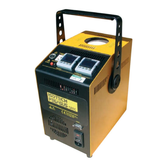
- Page 45 PLUS PEGASUS 1200 HANDBOOK ISSUE 5 - 01/05 FIGURE 2 Platinum Resistance Thermometer Connector Stir Speed Switch Contact (Thermostat) Thermocouple Connector Temperature Indicator Temperature Controller C o m m u n i c a t i o n s Connector On/Off Switch Power Entry and Fuse Page 45 of 50...
- Page 46 PLUS PEGASUS 1200 HANDBOOK ISSUE 5 - 01/05 Note: Only connect a thermocouple or platinum resistance thermometer to the input connectors. Ensure that only one sensor is connected at any time. Page 46 of 50...
-
Page 47: Troubleshooting
This is normal procedure - refer to page 15 Cannot establish PC Communications For RS232 you must use the Isotech adaptor cable. Ensure the addresses of the controller and indicator match those set in Cal Notepad. Ensure each controller and indicator are set to a unique address. -
Page 48: Accessories Parts List
PLUS PEGASUS 1200 HANDBOOK ISSUE 5 - 01/05 APPENDIX 2 ACCESSORIES PARTS LIST Type R Thermocouple 935-14-91 Undrilled Insert 853-06-02B Standard Insert 853-06-02A Special Insert Consult Factory Fuse 230VAC Models 20mm 10amp quick blow RS Components 416-405 PRT Plug 935-16-75 T/C Plug (Type R) 935-35-101 Rapid Air Cooling... - Page 49 PLUS PEGASUS 1200 HANDBOOK ISSUE 5 - 01/05 APPENDIX 3 INDICATOR CONFIGURATION (Reference Only) Config.INST Name Description Value unit Instrument Units ` C (0) dEcP Decimal Places in Display NNN.N (1) CtrL Control Type PID (0) Control Action REV (0) COOL Cooling Type LIN (0)
- Page 50 PLUS PEGASUS 1200 HANDBOOK ISSUE 5 - 01/05 Note: User Cal values are unique to each instrument. If available set values to those from calibration certificate Config.AL Name Description Value AL_1 Alarm 1 Type OFF (0) Ltch1 Alarm 1 Latching NO (0) AL_2 Alarm 2 Type...
Need help?
Do you have a question about the PEGASUS PLUS 1200 Series and is the answer not in the manual?
Questions and answers