
Related Manuals for Inter-m RM-6024


Summary of Contents for Inter-m RM-6024
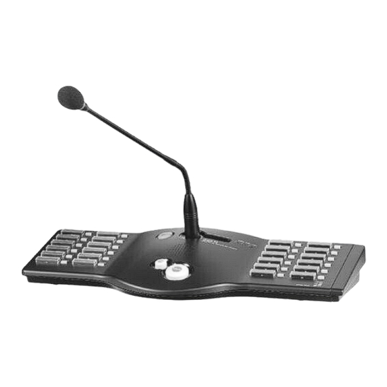
- Page 1 Operation anual System Remote MI Station/ 12Key MI Station Keypad RM-6024/RM-6012 P...
- Page 2 Welcome personal welcome to you from the management and employees of Inter-M ll of the co-workers here at Inter-M are dedicated to providing excellent products with inherently good value, and we are delighted you have purchased one of our products.
-
Page 3: Table Of Contents
....................4 Front Panel ............................7 Rear Panel ............................9 pplications ..........................11 Block Diagram ..........................12 Specifications ..........................13 Service ............................15 Procedures............................15 Schematic .............................15 Parts List ............................15 Warranty ............................15 "We, Inter-M to apply the appropriate set of E4 & Class for Electromagnetic Environment Condition." RM-6024/RM-6012KP... -
Page 4: Unpacking
SYSTEM REMOTE MIC ST TION/12KEY MIC ST TION KEYP D Unpacking Unpacking lthough your RM-6024 is neither complicated nor difficult to operate, we recommend you take a few minutes to read this brief manual and familiarize yourself with the important information regarding product features, setup and operation. -
Page 5: Features
Mixes an external sound source, so with MIC broadcasting, it can offer BGM capabilities. - RS-422 COMMUNIC TION llows remote mic (RM-6024) to be located up to a maximum distance of 1Km (3,280 feet) from RME-6108. Note: It is recommended that remote mic (RM-6024) be located within 500m (1,640 feet) of RME-6108. -
Page 6: Equipment Setting And Checking
2) When connecting an RM-6024 directly to an ECS-6216P: - The equipment number for the RM-6024 which is connected to RM1 terminal is labeled as “1”. - The equipment number for the RM-6024 which is connected to RM2 terminal is labeled as “9”. - Page 7 4) The table below shows the set-up method, and if D T number is added to switch turned ON, it will be the equipment number. Pin No. Data ddress (Ex: When No. 1 and 3 is ON, add 1 and 4 which is actual corresponding number, and then equipment number will be 5.) RM-6024/RM-6012KP...
- Page 8 3. ssemble the expansion keypad (RM-6012KP) - fter dissembling the RM-6024 side pad, connect the RM-6012KP and internal connector. - ssemble the RM-6024 and RM-6012KP using same instructions as above for side pad. - ssemble the dissembled side pad in RM-6012KP.
-
Page 9: Front Panel
4. POWER/F ULT/BUSY LED - POWER LED (GREEN) : displays the power input status. - F ULT LED (RED) : will be ON if communication error occurs. - BUSY LED (RED) : will blink if there is any higher priority broadcast. RM-6024/RM-6012KP... - Page 10 9. SIDE P D - fter disassembling the side pad, the KEYP D can be expanded by using RM-6012KP. - Up to 2 expansion keypads (RM-6012KP) can be connected. ※Caution: When connecting an expansion keypad (RM-6012KP) to RM-6024, power should be off. RM-6024/RM-6012KP...
-
Page 11: Rear Panel
Transmits the communication D T and UDIO signal. PIN NO. Functions RS-422 Data - TX+ RS-422 Data - TX- RS-422 Data - RX- Live Date RS-422 Data - RX+ Balanced udio Output - HOT Balanced udio Output - COLD RM-6024/RM-6012KP... - Page 12 - MIC Volume : adjust the MIC volume. - UX Volume : adjust the UX volume. 5. UX INPUT TERMIN L Used when broadcasting through the RM-6024 with an external sound source. In this case, MIC and sound sources will be mixed and transmitted. RM-6024/RM-6012KP...
-
Page 13: Pplications
9 10 11 12 13 14 15 16 EMG PANEL LOAD OPEN SPEAKER OUTPUT INPUT DC 24V ADDRESS 1 2 3 4 5 6 7 8 9 10 RM-6024 + RM-6012KP(x2) <ADDRESS SETTING: 9> RM-6024 + RM-6012KP(x2) <ADDRESS SETTING: 1> RM-6024/RM-6012KP... -
Page 14: Block Diagram
SYSTEM REMOTE MIC ST TION/12KEY MIC ST TION KEYP D Block Diagram Block Diagram RM-6024/RM-6012KP... -
Page 15: Specifications
SYSTEM REMOTE MIC ST TION/12KEY MIC ST TION KEYP D Specifications Specifications RM-6024 Channel 24CH Communication Protocol RS-422(Maximum 1km/3,280 feet) udio INPUT SENSTIVITY -60dB THD+N Less than 0.5% FREQUENCY RESPONSE 120Hz ~ 20kHz Better than 50dB INPUT SENSTIVITY -10dB THD+N Less than 0.5%... - Page 16 SYSTEM REMOTE MIC ST TION/12KEY MIC ST TION KEYP D ※ DIMENSIONS -RM-6024 -RM-6012KP 137.5 RM-6024/RM-6012KP...
-
Page 17: Service
To obtain specific warranty information and available service locations contact Inter-M directly or the authorized Inter-M Distributor for your specific country or region. - Page 18 NOTE RM-6024/RM-6012KP...
- Page 19 RM-6024/RM-6012KP...
- Page 20 Inter-M, Ltd. (Korea) began operations in 1983. Since then, Inter-M has grown to become one of the largest manufacturers of professional audio and commercial sound electronics equipment in the world. Inter-M has gained worldwide recognition for its own branded products, as well as private label manufacturing of electronics sold under other names (OEM).
Need help?
Do you have a question about the RM-6024 and is the answer not in the manual?
Questions and answers