Sign In
Upload
Manuals
Brands
Inovance Manuals
Power Supply
TD810 Series
Inovance TD810 Series Manuals
Manuals and User Guides for Inovance TD810 Series. We have
1
Inovance TD810 Series manual available for free PDF download: User Manual
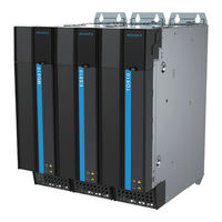
Inovance TD810 Series User Manual (254 pages)
Brand:
Inovance
| Category:
Power Supply
| Size: 24 MB
Table of Contents
Preface
2
Revision History
6
Table of Contents
7
Safety Instructions
12
Safety Precautions
12
Safety Levels and Definitions
12
Safety Instructions
13
Safety Signs
17
1 Product Information
18
Nameplate and Model Number
19
Components
21
2 Mechanical Installation
22
Precautions
22
Transportation Precautions
22
Storage Precautions
23
Installation Environment Precautions
23
System Selection
25
System Selection Flowchart
25
Selection of the Load and Motor
26
Selection of the Drive Unit
26
Selection of the Power Supply Unit
26
System Combination and Arrangement
28
System Selection Precautions
30
Cabinet Design
30
Space Requirements
30
Mounting Backplate Design Requirements
32
Cabinet Cooling Design
34
Combined Installation
39
Installation Method
39
Installation of the Power Supply Unit
41
Cabinet Installation
50
Auxiliary Installation for Cabinet Transportation
53
3 Electrical Installation
54
Main Circuit Wiring
55
Assignment of Terminals in the Power Supply Unit
55
Description of Terminals in the Power Supply Unit
57
Cable Selection
59
System Grounding
60
Control Circuit Wiring
61
Assignment of Terminals in the Power Supply Unit
61
Control Circuit Wiring Requirements
66
Description of Control Circuit Wiring
67
4 Panel Operations
70
LED Operating Panel
70
Function Indicators
70
LED Display Area
71
Key Functions
71
Parameter Viewing and Modification Methods
72
Parameter Viewing
73
External LCD Operating Panel
79
Appearance and Page
79
Wiring
80
Status Viewing
81
Parameter Setting
82
Parameter Copy
83
Fault Query
84
Inodriveshop
84
5 Parameter Description
85
Basic Information
85
Parameter Settings of Basic Functions
85
Information Exchange Setting between the Power Supply and Drive Units
88
Input Terminal Functions
90
Relay Output Terminal Functions
92
Fault Record Group
93
Parameter Management
96
Monitoring Parameters
98
6 Communication
102
Parameter Communication Address
102
Parameter Introduction
102
Description of Parameter Communication Addresses
102
Modbus-Specific Parameter Communication Addresses
104
Modbus Communication
106
Networking
106
Interface Description
106
Communication Performance
106
Related Parameters
107
Modbus Communication Protocol
108
Communication Data Frame Structure
109
Canopen/Canlink Communication
113
Networking
113
Interface Description
113
CAN Bus Topology
114
CAN Transmission Distance
114
Related Parameters
114
Description of Canopen Communication Protocol Application
117
Canopen Communication Protocol
126
PROFIBUS-DP Communication
129
Networking
129
Interface Description
129
Baud Rate and Communication Distance
130
Relevant Parameters
130
PROFIBUS-DP Communication Protocol Description
130
Switching the PROFIBUS-DP to the Canopen Network Bridge
142
Networking
142
Interface Description
142
Communication Performance
142
Related Parameters
143
Fault Description
145
Description of Application
146
Canopen Slave Configuration Description
151
PLC Fault Diagnosis
155
PROFINET-To-Canopen Network Bridge
155
PROFINET Overview
155
Configuration Preparation
156
Process Data Configuration on the AC Drive
156
Configuration on STEP
160
Configuration on TIA Portal
165
Auxiliary Functions
168
Error Reporting and Diagnosis
168
Monitoring
169
Configuration of PROFINET Network Bridge Used with Siemens PLC S1500
169
7 Troubleshooting
190
Safety Information
190
Fault Display and Solutions
191
Fault Codes and Solutions
192
Symptoms and Solutions
195
8 Maintenance
197
Daily Inspection
198
Periodic Inspection
198
Periodic Inspection Items
198
Insulation Test on the Main Circuit
200
Replacing Cooling Fans
200
Number of Cooling Fans on the Power Supply Unit
201
Removing and Installing Fans
202
9 Technical Data and Options
206
Technical Data
206
Installation Dimensions
208
Options
209
Co-Bus External Power Terminal
210
Embedded Mounting Bracket and Backplate Tapping Dimensions
211
Heat Insulation Baffle
211
Shielded Bracket
212
External LCD Operating Panel
213
Selection of Braking Components
213
Selection of Resistance of the Braking Resistor
213
Selection of Power of the Braking Resistor
213
Selection Guidance
214
Overall Dimensions and Installation Dimensions of Braking Unit
215
Overall Dimensions of Energy Feedback Unit
217
Selection of Electrical Peripherals
219
MCCB and Contactor
219
Lugs
220
AC Input Reactor
224
External EMC Filter
227
Appendix A Standards Compliance
235
CE Certification
235
CE Low Voltage Directive Compliance
235
EMC Guidelines Compliance
236
Definition of Terms
237
Cabling Requirements
238
Solutions to Current Leakage
238
Solutions to Common EMC Interference Problems
239
Appendix B Parameter Table
241
Standard Parameters
241
Power Supply Unit Monitoring Parameters
251
Warranty Agreement
253
Advertisement
Advertisement
Related Products
Inovance T7 MD520-4T45(B)(S)
Inovance T8 MD520-4T75(B)(S)
Inovance 810 Series
Inovance ES810 Series
Inovance GL20-PS2
Inovance Categories
Servo Drives
DC Drives
Controller
Control Unit
Inverter
More Inovance Manuals
Login
Sign In
OR
Sign in with Facebook
Sign in with Google
Upload manual
Upload from disk
Upload from URL