Table of Contents
Advertisement
Quick Links
Advertisement
Table of Contents

Related Manuals for Panasonic KW4M


Summary of Contents for Panasonic KW4M
- Page 2 Copyright and trademark ● Panasonic Electric Works Co., Ltd. owns the copyright of this manual. ● We stiffly refuse the reproduction of without permission from this manual. ●Modbus Protocol is a communication protocol that the Modicon Inc.developed for PLC.
- Page 3 Introduction Thank you for indeed for purchasing “KW4M Eco-POWER METER” for this time. In this manual, we explain the usage of “KW4M Eco-POWER METER” in detail. Please use it correctly after understanding the content enough.
-
Page 4: Table Of Contents
Table of Contents Cautions before using ..........................ⅰ Chapter 1 Unit’s Features and Structure....................1 1-1 Features..............................1 1-2 Unit’s Name and Part Numbers....................... 1 1-2-1 Main unit............................1 1-2-2 Dedicated Current Transformer (CT)..................... 1 1-2-3 Options............................1 1-3 Measurement items ..........................2 Chapter 2 Parts Name and Working ....................3 2-1 Parts Names ............................ - Page 5 Chapter 8 Specifications ........................33 8-1 Main unit ..............................33 8-2 Input Specifications ..........................34 8-2-1 Power Input..........................34 8-2-2 Pulse input specifications......................35 8-3 Pulse output (Transistor output) Specifications..................35 8-4 Communication Specifications ......................36 8-5 Dedicated Current Transformer Specifications ..................36 8-6 Self-diagnostic function .........................
-
Page 6: Cautions Before Using
Cautions before using ■ Installation environment ◇Do not use the Unit in the following environments. ・Where the unit will be exposed to direct sunlight and where the ambient temperature is outside the range of -10 to 50 °C. ・Where the ambient humidity is outside the range of 30 to 85 % RH (at 20℃ non-condensing) and where condensation might occur by sudden temperature changes ・Where inflammable or corrosive gas might be produced ・Where the unit will be exposed to excessive airborne dust or metal particles... -
Page 7: Features
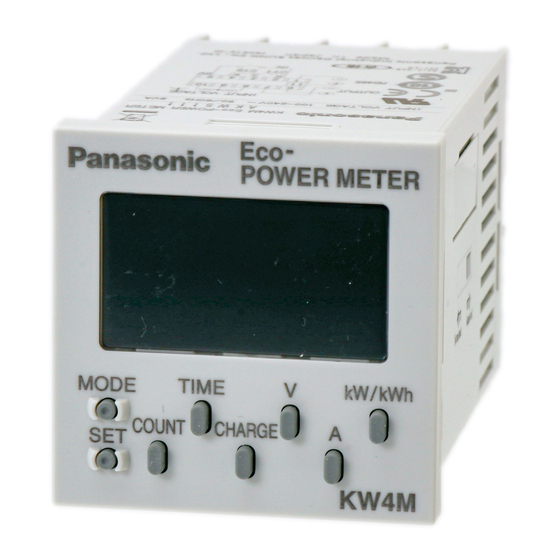
Unit’s Features and Structure 1-1 Features ■KW4M Eco-POWER METER is a wattmeter in DIN48 size. Electrical energy (voltage, current, etc.) is measured using AC voltage and AC current input via one of the following systems: single-phase two-wire system, single-phase three-wire system, or three-phase three-wire system. -
Page 8: Measurement Items
1-3 Measurement items Item Unit Data displayed range Instantaneous electric power 0.00 to 9999.99 0.00 to 9999.99kWh to 10.00MWh to Integrated electrical energy 9999.99MWh 9-digit display: 0.00 to 9999999.99 kWh L1(CT1)-phase current 0.0 to 6000.0 Current L2(CT2)-phase current 0.0 to 6000.0 Voltage between 1-2 0.0 to 9999.9 Voltage... -
Page 9: Chapter 2 Parts Name And Working
Chapter 2 Parts Name and Working 2-1 Parts Names ① Mode name display (16-segment) ② ① ② Lock indicator Light is on when locked. ③ ③ Mode indicator Light is on when the mode is being set. ⑥ ④ ④ Output indicator Light is on when pulse is output. -
Page 10: Chapter 3 Display Of Each Value
Chapter 3 Display of each Value 3-1 Instantaneous electric power / Integrated Electrical energy ・Press <kW/kWh>key to display the instantaneous electric power and integrated electrical energy. ・Press <kW/kWh>key to change the instantaneous electric power to integrated electrical energy. *Displayed data is updated at every 1 second. Instantaneous electric power(kW) →... -
Page 11: Current
3-2 Current ・Press <A>key to display the current value of the load. ・Press <A>key to change L1(CT1)-phase current to L2(CT2)-phase current *Displayed data is updated at every 1 second. → L1(CT1)-phase current (A) L2(CT2)-phase current (A) Sample of L1(CT1)-phase 30.0A Sample of L2(CT2)-phase 30.1A <A>... -
Page 12: Electricity Charge
3-4 Electricity Charge It displays the standard electricity charge or corresponding value for the integrated electrical energy. ・Press <CHARGE>key to display the electricity charge and corresponding value. ・At electricity charge display, press <CHARGE>key to change between JPY, $, EUR, CNY, CHG and CO2. →... -
Page 13: Count Value / Preset Value
*After reaching the full scale (99999.9h), the value reverts to 0.0h but continues to measure. CT Detection Full scale ON-time OFF-time How to Reset ON/OFF-time ・Press <MODE>key while pressing <SET>key makes ON / OFF-time clear. Reset <SET> <MODE> 3-6 Count Value / Preset Value It displays present count value (pulse input value) and preset value. -
Page 14: Chapter 4 Various Functions
Chapter 4 Various Functions 4-1 LOCK mode It is the mode makes <MODE>key and Select keys unable. Use when you want to fix one of the measurement displays (For all displays). When you press <SET>key continuously for about 3sec., the “LOCK” indicator lights and <MODE>key and Select keys become locked (pressing them will have no effect). -
Page 15: Chapter 5 Settings
Chapter 5 Settings 5-1 Operation procedure Each setting is classified as follows. There are the detailed explanations from next pages. ・MODE:<MODE> …Mode for selection of Power measurement (Power meter) or Pulse measurement (Pulse counter). ・MODE1: <MODE>+<kW/kWh> … Mode for setting each parameter for power measurement. ・MODE2: <MODE>+<A>... -
Page 16: Setting Mode Explanation
5-2 Setting Mode Explanation ■The value with under line is initial setting among each setting value. ☆Set before measurement. 5-2-1 MODE (Select input method) <MODE> Input method setting mode Mode defines input method, power measurement or pulse measurement. ・Select from POWER / COUNT ・“POWER”... - Page 17 C U T A Cutoff current setting mode Mode defines load current that does not measured (Cutoff current). Use to avoid miss-measurement by wiring or induction noise at no-load. 0.00kW is displayed for instantaneous electric power, 0.0A is displayed for current. Integrated electrical energy is not measured.
- Page 18 VT ratio setting mode Factory setting / Display ・Enter VT ratio using<kW/kWh>,< A >,< V >,<CHARGE>. ・ If the VT is 440/110, set to “ 4.00 ”. (1.00~99.99) ↓ <SET> Current for time measurement setting mode Factory setting / Display ・...
-
Page 19: Mode2
5-2-3 MODE2 (Mode for setting each parameter for pulse measurement. This mode doesn’t show when power measurement is selected.) <MODE>+< A > Max. counting speed setting mode Mode defines max. counting speed. ・Select from 2kHz/30Hz P S C L Pre-scale setting mode Mode defines pre-scale value used for change count value. -
Page 20: Mode3
5-2-4 MODE3 (Mode for setting of each parameter for serial communication (RS-485)) <MODE>+< V > N O . Station number setting mode Mode defines an individual station no. for each unit when two or more units communicate via serial communication (RS-485). ・It can be set the range of 01 to 99. -
Page 21: Mode4
Response time setting mode Factory setting / Display Enter the response time using <kW/kWh>, < A >. ・ Response time can be entered the range of 05 to 99ms. ↓ <SET> Normal display 5-2-5 MODE4 (Mode for setting of each parameter for optional function) <MODE>+<CHARGE>... -
Page 22: Chapter 6 Installation And Wiring
Chapter 6 Installation and Wiring 6-1 Panel Cut-out dimensions (Unit: mm) +0.6 Dimension A when ‘u’ products are mounted in a row: A=(48*n-2.5) If the products are mounted in a row, they lose their waterproofing properties. 6-2 Panel mounting diagram How to mount From the panel front, pass the main unit through the square holes. -
Page 23: Wiring
6-3 Wiring 6-3-1 Terminal arrangement Terminal No. Functions Pin type Screw terminal type ① ⑧ 1, R, R ② ⑨ 2, N, S ③ ⑩ 3, T, T ⑪ ④ (+) RS-485 ⑤ ① (-) ⑥ ⑥ (+) Pulse output ⑦... - Page 24 ②Single-phase 3 wire system / Three-phase 3 wire system *Two CTs are required to measure Single-phase 3-wire / Three-phase 3 wire system. < Pin type > <Screw terminal type> 2) When measuring load with 200V or more system VT (Voltage transformer) is needed when you measure a load with voltage over 200V system. Use commercial VT, those secondary rating is 110V.
- Page 25 ◇To connect CT with secondary current 5A How to connect the unit to measure by combination with existing commercial CT (1) Select 5A at CT type setting mode (CT-T). (2) Set the primary current of measured commercial CT (secondary current 5A) at primary side current of CT setting mode (CT-1).
-
Page 26: Pulse Measurement
6-3-3 Pulse measurement ◇Main unit wiring diagrams < Pin type > <Screw terminal type> ◇Input connection ・Contact input Use highly reliable metal plated contacts. Since the contact’s bounce time leads directly to error in the count value, use contacts with as short a bounce time as possible. In general, ⑤... -
Page 27: For Output Connection
6-3-4 For Output connection Since the transistor output is insulated from the internal circuit by a photo-coupler, it can be used both as a NPN output and PNP (equal value) output. Eco-POWER METER Eco-POWER METER NPN output Pulse(+) Pulse(-) PNP output Pulse(+)... -
Page 28: Low Voltage Directive
Recommended Cable Use the transmission cables shown below for Eco-POWER METER RS485 communication system. Conductor Insulator Cable Cable Resistance Applicable cable diameter Size Material Thickness (at 20℃) HITACHI 1.25 mm KPEV-S Max. Approx. (AWG16) Max.16.8Ω/km Polyetheline ×1P 0.5 mm 8.5 mm 1.25 mm or more Twisted-... -
Page 29: Chapter 7 Communications
Chapter 7 Communications 7-1 Communication Procedures Communication starts with command transmission from the host computer (hereafter Master) and ends with the response of Eco-POWER METER (hereafter Slave). Master Slave • Response with data Command When master sends reading command, slave responds with the Data corresponding set value or current status. -
Page 30: Mewtocol Communication
7-3 MEWTOCOL communication 7-3-1 Overview of MEWTOCOL-COM (RS-485) ◆Command and response functions The computer sends commands (instructions) to Eco-POWER METER, and receives responses in return. This enables the computer and Eco-POWER METER to converse with each other, so that various kinds of information can be obtained and provided. ①Commands Computer Eco-POWER METER... -
Page 31: Data Register List
7-3-2 Data Register List Data register Name Unit Kind of data Range Rate ¥(JPY) DT00050 0.1¥ 0 to 99.9 Sign-less 16bit Rate $ 0.001$ DT00051 0.000 to 9.999 Sign-less 16bit DT00052 Rate €(EUR) 0.001€ 0.000 to 9.999 Sign-less 16bit DT00053 Rate yuan (CNY) 0.01 yuan 0.00 to 99.99... -
Page 32: Error Codes
4) If each setting value is wrote by communication, it memories to internal EEP-ROM at the same time. Therefore, change setting frequently makes EEP-ROM’s life short. Avoid to usage like this. 5) Write a data within the range when you write it. 7-3-3 Error Codes ◇Basic procedure errors Error code... - Page 33 ◆[RD]: Read data area (Reads the contents of data area.) ◇Command Ending word No. Starting word No. Destination % # 5 characters 5 characters ×10 ×10 ×10 ×10 ×10 ×10 ×10 ×10 ×10 ×10 ×10 ×10 ×16 ×16 ◇Normal response (Read successful) First register contents Last register contents Source...
-
Page 34: Modbus (Rtu) Communication
7-5 MODBUS (RTU) Communication 7-5-1 Overview of MODBUS (RTU) ◆8-bit binary data in command is transmitted as it is. Data format Start bit : 1 bit : 8 bits ※7bits is not available. Data bit Parity : No parity, Even parity, Odd parity Selectable Stop bit : 1 bit (Fixed) Error detection... - Page 35 ◇Data: Data depends on the function code. A request message from the master side is composed of data item, number of data and setting data. A response message from the slave side is composed of number of bytes, data and exception code in negative acknowledgement.
- Page 36 ③ Reset integrated electric power (0064H, 0065H:2-word) of address 1 (When setting to 0 [0000, 0000H]) ・Command Number of Slave Function Data item Number of 3.5 idle data item to ⇒ address code data characters write (01H) (10H) (0064H) (04H) (0002H) ←character number...
-
Page 37: Data Register List
7-4-2 Data Register List MODBUS Range: Hexadecimal Data item Function Name Unit Kind of date (Range: Decimal) (MEWTOCOL) code 0H~270FH 0032H Sign-less Rate ¥(JPY) 03H/06H/10H 0.01 (DT00050) 16bit (0~9999) Sign-less 0033H 0H~270FH 03H/06H/10H Rate $ 0.001$ (DT00051) 16bit (0~9999) 0034H Sign-less 0H~270FH 03H/06H/10H... - Page 38 009AH (DT00154) Sign-less 0H~F423FH - 03H/06H/10H Pulse count value 32bit (0~999999) 009BH (DT00155) 009EH 0H~F423FH (DT00158) Sign-less - 03H/06H/10H Preset value 32bit (0~999999) 009FH (DT00159) 00A0H 1H~186A0H (DT00160) Sign-less 0.001 03H/06H/10H Pre-scale value (1~100000) 32bit 00A1H *Decimal point is fixed. (DT00161) 00A2H Sign-less...
-
Page 39: Chapter 8 Specifications
Chapter 8 Specifications 8-1 Main unit Rated operating voltage 100-120/200-240V AC Rated frequency 50/60Hz common Rated power consumption Allowable operating 85-132/170-264V AC(85%~110% of rated operating voltage) voltage range Allowable momentary 10ms power-off time Ambient temperature -10~+50℃(-25℃ to +70℃ at storage) Ambient humidity 30~85%RH(at 20℃... -
Page 40: Input Specifications
8-2 Input Specifications 8-2-1 Power Input Instantaneous electric power (kW) Power Integrated electrical energy (kWh, MWh) Voltage Each phase Voltage (Between 1 and 2, 2 and 3) (V) Measuring Each phase Current item Current (L1(CT1)-phase current, L2(CT2)-phase current) (A) Electricity charge Integrated electricity charge (JPY,$,EUR,CNY) Power-on time Hour Meter (Load ON-time, Load OFF-time) (hour) -
Page 41: Pulse Input Specifications
Instantaneous electric power, Integrated electrical energy Voltage, Current, Electricity charge, Corresponding value ±2.5% F.S. ±1digit (at 20℃, rated input, rated frequency, power-factor 1) Basic ※Accuracy coverage:10~100% of rated current of CT accuracy Accuracy Hour Meter (without error ±0.01%±1digit (at 20℃) in CT and VT) (In case power on start or current energizing,±0.01%+1s±1 digit) ±1.5% F.S. -
Page 42: Communication Specifications
8-4 Communication Specifications Interface Conforming to RS-485 Protocol MEWTOCOL/MODBUS (RTU) (different model) Isolation status Isolated with the internal circuit ※ ※ Number of connected units 99 (max.) Transmission distance 1200m Transmission speed 38400/19200/9600/4800/2400bps (selectable with setting mode) 8bit/7bit (selectable with setting mode) (MEWTOCOL type) Data length 7bit (fixed) -
Page 43: Self-Diagnostic Function
8-6 Self-diagnostic function If an error occurs, the following indication will be given. Indicator Meaning Output status To recover Err-00 CPU error Turn the power off and then on again. Err-01 Memory error* EEP-ROM life ended. Replace the unit. *Includes the possibility that the EEP-ROM’s life has expired. Chapter 9 Dimensions 9-1 Main unit (Unit: mm) -
Page 44: Dedicated Ct
9-2 Dedicated CT (Unit: mm) (Clearance: ±1.0) ◆For 5A/50A(AKW4801) ◆For 100A(AKW4802) ◆Attached trunk cable: L=(1000) - Page 45 ◆For 250A(AKW4803) ◆For 400A(AKW4804)...
- Page 46 Revision History Issue Date Manual no. Content of revision June, 2005 ARCT1F413E First edition October, 2007 ARCT1F413E-1 Second edition 6-3 Wiring: Add the explanation in detail. March, 2008 ARCT1F413E-2 Third edition MODBUS type series addition ・Model No. ・MODBUS communication ・MODBUS specifications October, 2008 ARCT1F413E-3 Fourth edition...
Need help?
Do you have a question about the KW4M and is the answer not in the manual?
Questions and answers