Ubiquiti airFiber AF 60 Quick Start Manual
Hide thumbs
Also See for airFiber AF 60:
- Quick start manual (42 pages) ,
- Quck start gude (23 pages) ,
- Quick start manual (34 pages)

Related Manuals for Ubiquiti airFiber AF 60


Summary of Contents for Ubiquiti airFiber AF 60
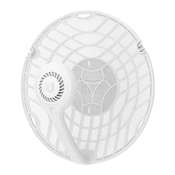
- Page 1 AF60 Quick Start Guide Package Contents Dish Main Arm Stabilizer Arms (Qty. 2) Mounting Bracket Screw U-Clamp Flat Washers (Qty. 2) Lock Washers (Qty. 2) Flange Nuts (Qty. 2) Gigabit PoE (24V, 0.5A) with Mounting Bracket Power Cord...
-
Page 2: Installation Requirements
Installation Requirements Clear line of sight between airFiber AP and station Clear view of the sky for proper GPS operation Vertical mounting orientation Mounting point: At least 1 m below the highest point on the structure For tower installations, at least 3 m below the top of the tower Outdoor, shielded Category 6 (or above) cabling and shielded RJ45 connectors are required for all wired Ethernet connections. -
Page 3: Hardware Overview
Hardware Overview GPS LED The LED will light blue when the GPS signal strength is sufficient. This requires Blue a minimum of three GPS satellite connections. 60G LED Blue The LED will light blue when the 60 GHz link is ready. 5G LED... -
Page 4: Installation Overview
The LED will light steady blue when an active Ethernet connection is made to Blue the Ethernet port and flash when there is activity. Power LED Flashing White Bootup in progress. Ready for use, not connected to Ubiquiti® Network Management System White (UNMS™). See “UNMS Management”. Blue Ready for use, connected to UNMS. -
Page 5: Configuring The Settings
Configuring the Settings The device is set to DHCP by default, so it will try to automatically obtain an IP address. If that fails, it will use the default fallback IP address, 192.168.1.20. Proceed to the appropriate section, “DHCP” “Fallback IP Address”: DHCP Use one of the following methods:... - Page 6 Set up the DHCP server to provide a specific IP address to the device based on its MAC address (on the label). Let the device obtain an IP address and then check the DHCP server to see which IP address was assigned. 1.
- Page 7 Note: The key is an alphanumeric password between 8 and 63 characters long. 6. Click Save Changes. 7. Configure each airFiber radio with a unique IP address: a. Click the icon. b. Review the Network settings to ensure that each airFiber radio has a unique IP address. Each can get its IP address via DHCP, or use a static IP address.
-
Page 8: Installation
6. Click the icon. 7. Configure the following settings: a. For one airFiber radio, enable Access Point mode. For the other airFiber radio (the Station), keep Access Point disabled. b. Enter a name in the SSID field. This must be the same on both the AP and the Station. c. - Page 9 Optional Attach the stabilizer arms for added support.
- Page 10 (This is recommended for long-range installations.)
- Page 11 Note: The AF60 can mount on either side of the pole. This section shows the AF60 mounted on the left; the procedure for mounting on the right is similar. Left Right...
- Page 12 Note: Rotate the Mounting Bracket clockwise until it locks into position.
- Page 14 (Pole not shown)
-
Page 16: Connecting Power
Connecting Power WARNING: The switch port must comply with the power specifications listed in “Specifications”. -
Page 17: Establishing A Link
Optional Alignment Tips To accurately align the airFiber radios for best performance, you MUST align only one end of the link at a time. You may need to use additional hardware to compensate for issues such as the improper orientation of a mounting pole or significant elevation differences between airFiber radios. - Page 18 Adjust the elevation: Note: Do NOT make simultaneous adjustments on the AP and Station. Station Visually aim the Station at the AP. To adjust the Station’s position, adjust the azimuth and elevation as described in...
-
Page 19: Installer Compliance Responsibility
step 1. 3. Open the Configuration Interface, select Tools, and then select Align Antenna. 4. Repeat steps 1-2 until you have achieved an optimal link and both the 60G and 5G LEDs are solidly lit blue. This ensures the best possible data rate between the airFiber radios. Note: Maximum signal strength can best be achieved by iteratively sweeping through both azimuth and elevation. -
Page 20: Specifications
Antenna The 5GHz Output Power field is provided to the professional installer to assist in meeting regulatory requirements. Specifications AF60 Dimensions 413 x 413 x 320 mm (16.26 x 16.26 x 12.60") Weight Without Mount 1.4 kg (3.09 lb) With Mount 1.8 kg (3.97 lb) Enclosure Aluminum, UV-stabilized Polycarbonate... -
Page 21: Safety Notices
(94.4 lbf @ 125 mph) Wind Survivability 200 km/h (125 mph) ESD/EMP Protection ± 24kV Contact/Air Operating Temperature -40 to 60° C (-40 to 140° F) Operating Humidity 5 to 95% Noncondensing Certifications FCC, IC, CE System Maximum Throughput 1.8 Gbps Maximum Range 2+ km Encryption... -
Page 22: Electrical Safety Information
3. Only use attachments/accessories specified by the manufacturer. WARNING: Do not use this product in location that can be submerged by water. WARNING: Avoid using this product during an electrical storm. There may be a remote risk of electric shock from lightning. Safety Notices 1. -
Page 23: Limited Warranty
outlet as this will defeat the continuity of the grounding wire. b. The equipment requires the use of the ground wire as a part of the safety certification, modification or misuse can provide a shock hazard that can result in serious injury or death. c. - Page 24 IMPORTANT NOTE: Radiation Exposure Statement: This equipment complies with radiation exposure limits set forth for an uncontrolled environment. This equipment should be installed and operated with minimum distance 71 cm between the radiator and your body. This transmitter must not be co-located or operating in conjunction with any other antenna or transmitter. AVIS IMPORTANT : Déclaration sur l’exposition aux rayonnements : Cet équipement est conforme aux limites prévues pour l’exposition aux rayonnements dans un environnement non contrôlé.
-
Page 25: Weee Compliance Statement
Note: Fixed service or any restrictions for authorization of use shall follow local country regulations. The following apply to products that operate in the 5 GHz frequency range: Note: This device is restricted to indoor use only when operating in the 5150 - 5350 MHz frequency range within all member states. Note: All countries listed may operate at 30 dBm. - Page 26 IMPORTANT NOTE: Radiation Exposure Statement: This equipment complies with radiation exposure limits set forth for an uncontrolled environment. This equipment should be installed and operated with minimum distance 71 cm between the radiator and your body. This transmitter must not be co-located or operating in conjunction with any other antenna or transmitter. AVIS IMPORTANT : Déclaration sur l’exposition aux rayonnements : Cet équipement est conforme aux limites prévues pour l’exposition aux rayonnements dans un environnement non contrôlé.
-
Page 27: Declaration Of Conformity
Note: Fixed service or any restrictions for authorization of use shall follow local country regulations. The following apply to products that operate in the 5 GHz frequency range: Note: This device is restricted to indoor use only when operating in the 5150 - 5350 MHz frequency range within all member states. Note: All countries listed may operate at 30 dBm. - Page 28 © 522812020 Ubiquiti Inc. All rights reserved.
Need help?
Do you have a question about the airFiber AF 60 and is the answer not in the manual?
Questions and answers