Table of Contents
Advertisement
Advertisement
Table of Contents

Related Manuals for Smith & Nephew LENS Integrated System


Summary of Contents for Smith & Nephew LENS Integrated System
- Page 1 Operations/Service Manual LENS Integrated System...
-
Page 3: Glossary Of Symbols
Authorized representative Do not plug in wet Equipotentiality in the European community Alternate current Keep dry This way up Warning Humidity limitation Temperature limitation Electrical Equipment MR Unsafe Safety System (EESS) LENS Integrated System Operations/Service Manual 10601034 Rev. B... -
Page 4: Table Of Contents
Preface This manual provides the information needed to operate and maintain the Smith & Nephew LENS Integrated System. Prior to using this equipment, read this manual thoroughly, paying particular attention to the operating instructions, warnings, and precautions. Smith & Nephew surgical equipment is designed for use only by medical professionals who are completely familiar with the appropriate surgical techniques and video procedures. -
Page 5: Device Description
Device Description Device Description Warnings The Smith & Nephew LENS Integrated System (the System) is a • It is the surgeon’s responsibility to be familiar with the state-of-the-art video system designed for use in endoscopic appropriate surgical techniques prior to use of this device . -
Page 6: If Using The Wi-Fi Enabled Control Unit
Connection to this CCU likely will equipment should be in the 75U (ohm) or the ON position if the increase the leakage current at the CCU’s chassis. equipment provides that option. LENS Integrated System Operations/Service Manual 10601034 Rev. B... -
Page 7: System Components
Accessories See the “Ordering Information” section of this manual for more information about couplers. LENS Integrated System Operations/Service Manual 10601034 Rev. B... -
Page 8: System Controls
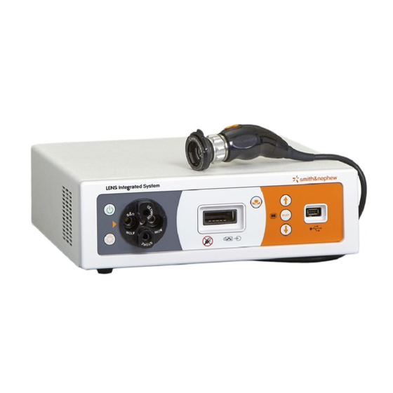
System Controls System Controls Front Panel Overview LENS Integrated System Figure 1 . LENS Integrated System Camera Control Unit Front Panel Front Panel Control/Connector Function 1. Standby System Power button Turns the control unit on and off. The rear power switch must be switched to the (I) position in order to provide mains power to the system. -
Page 9: Rear Panel Overview
System Controls Rear Panel Overview Figure 2 . LENS Integrated System Camera Control Unit Rear Panel (REF 72204354 - Wi-Fi enabled, REF 72204685 - no Wi-Fi) Rear Panel Connections Function 1. HD-DVI Output A high-definition digital visual interface (1080p) output for DVI-compatible HD digital displays. The DVI-I connector supports DVI-D (DVI-Digital) single-link interfaces. -
Page 10: Camera Head Controls
Short press Middle Long press button Left Short press Short press Right button Long press Long press button Figure 3 . Smith & Nephew LENS Autoclavable Camera Head LENS Integrated System Operations/Service Manual 10601034 Rev. B... -
Page 11: Button Function
Triggers the accessory connected to the top port Peripheral Port 2 (Bottom port) Triggers the accessory connected to the bottom port * Note: Button-mappable functions may change without notice as a result of updates to the software of the LENS Integrated System. LENS Integrated System Operations/Service Manual... -
Page 12: General Screen Navigation
3. Screen name 4. Active menu area 5. Name of highlighted function 6. Button navigation map (top = short press (<1 seconds), bottom = long press (>1 seconds)) Figure 4 . Sample on-screen display LENS Integrated System Operations/Service Manual 10601034 Rev. B... -
Page 13: Installation
Unpacking and General Inspection • If this unit is configured as part of a system, the entire system Prior to using the LENS Integrated System, it is essential that all system should be tested for compliance with IEC 60601-1 . -
Page 14: Cable Connectors
To connect, push in and turn. Note: BNC/SDI and BNC/HDSI connectors appear identical. For the highest quality image, be sure to use the cable provided with the System. Mini Phono Plug To connect, push in firmly. LENS Integrated System Operations/Service Manual 10601034 Rev. B... -
Page 15: Recommended System Configuration For The Wi-Fi-Enabled System
Once the Wi-Fi-enabled System has been turned on, the iPad can be connected using the App. If using the non-Wi-Fi version of the System, the iPad and App cannot be used. LENS Integrated System Operations/Service Manual 10601034 Rev. B... - Page 16 Installation Figure 5 . Recommended setup configuration, Wi-Fi enabled System LENS Integrated System Operations/Service Manual 10601034 Rev. B...
-
Page 17: Recommended System Configuration, No Wi-Fi
660HD HD-SDI output to the flat panel display. The 660HD image management system is compatible only with 1080i output. Refer to the “Advanced Settings” section of this manual for information about how to configure input and output settings. LENS Integrated System Operations/Service Manual 10601034 Rev. B... - Page 18 Installation Fluoroscopy, in-room camera, etc. LENS Integrated System 100-240V~, LENS Integrated System MEDICAL EQUIPMENT WITH RESPECT TO ELECTRICAL 50/60Hz, 250 VA SHOCK, FIRE, AND MECHANICAL HAZARDS ONLY IN Integriertes System • Sistema integrado • Système intégré • Sistema integrato • Integrerat system •...
-
Page 19: Apply Power To The Camera Control Unit
The right side of the icon is white, which indicates that the secondary video input (image management system, fluroscopic device, etc.) is not operational or not connected and should be checked. LENS Integrated System Operations/Service Manual 10601034 Rev. B... -
Page 20: Preoperative
Damage to the unit may occur if the light guide is Note: The camera head is not specific to any single LENS camera not inserted into the port associated with the correct light guide control unit. It can be used with multiple LENS Integrated System control manufacturer. units. -
Page 21: Connect The Ipad
Inspect the System Components Prior to using the LENS Integrated System, it is essential that all system components be inspected for damage which can negatively impact the system’s performance. Inspection should include all equipment to be used in surgery, including cables and peripheral devices. -
Page 22: Safety And Service Life Checklist
. Ensure there are no deposits, scratches, or fogging/ humidity on the front window of the camera head . Ensure that the system is ready and safe to use. LENS Integrated System Operations/Service Manual 10601034 Rev. B... -
Page 23: Operation
Note: Settings changed directly from the MAIN MENU are temporary settings and will not be saved after the system is powered down or another procedure is selected. To save settings permanently, refer to the “Customize Procedure Settings” section of this manual. LENS Integrated System Operations/Service Manual 10601034 Rev. B... -
Page 24: Procedures
To customize a procedure, highlight the CUSTOMIZE PROCEDURE SETTINGS icon on the CUSTOMIZE PROCEDURES menu (Figure 17) and To exit the SYSTEM CONFIGFURATION MENU screen, navigate to the press Select. Exit icon and press Select. Figure 17 . LENS Integrated System Operations/Service Manual 10601034 Rev. B... -
Page 25: Capture Images
If using the 660HD, images will be stored directly to that device. Buttons must be mapped to the appropriate peripheral port. The patient information box will not appear on the OSD. LENS Integrated System Operations/Service Manual 10601034 Rev. B... -
Page 26: Security Settings
Note: The system clears access either on power down or by accessing the power standby button on the front panel. LENS Integrated System Operations/Service Manual 10601034 Rev. B... -
Page 27: Menu Maps
PORTS CAMERA BUTTON MAPPINGS SYSTEM PASSWORD CONFIGURATION RESET FACTORY LANGUAGE NETWORK DEFAULTS BUTTONS POP UP MENUS ADVANCED VERSIONS SETTINGS ZOOM BRIGHTNESS ENHANCEMENT WHITE BALANCE EXIT TO MAIN MENU EXIT TO MAIN MENU LENS Integrated System Operations/Service Manual 10601034 Rev. B... -
Page 28: Postoperative
• If a USB is used for data storage, all images are saved as MP4 files to a media directory. To print from the media directory, the user must have the directory structure and know how to navigate the directory (Figure 19). Figure 19 . LENS Integrated System Operations/Service Manual 10601034 Rev. B... -
Page 29: Customize The System
SAVE AND EXIT to return to the SYSTEM CONFIGURATION MENU screen. To exit the screen without saving any changes, navigate to CANCEL and press Select to return to the SYSTEM Figure 22 . CONFIGURATION MENU screen. LENS Integrated System Operations/Service Manual 10601034 Rev. B... -
Page 30: Set/Change Admin Password
Select. To exit the keyboard, original settings and select Save and Exit . navigate to the Return key and press Select. LENS Integrated System Operations/Service Manual 10601034 Rev. B... -
Page 31: Language
SAVE AND EXIT to return to the SYSTEM CONFIGURATION MENU screen. To exit the screen without saving any changes, navigate to CANCEL and press Select to return to the SYSTEM CONFIGURATION MENU screen. Figure 31 . LENS Integrated System Operations/Service Manual 10601034 Rev. B... -
Page 32: Advanced Settings
Select to select it. The current channel will blink. 2. Use the Up and Down arrows on the control unit or the left and right camera head buttons to navigate to the desired channel and press Select. LENS Integrated System Operations/Service Manual 10601034 Rev. B... -
Page 33: To Configure Hdsdi Outputs
2. Use the Up and Down arrows on the control unit or the left and right camera head buttons to scroll through the available options (Figure 35). Press Select to activate the desired option. POWER LOSS ALWAYS NEVER Figure 35 . LENS Integrated System Operations/Service Manual 10601034 Rev. B... -
Page 34: Customize Procedure Settings
2. Use the Up and Down arrows on the control unit or the left and right camera head buttons to switch between OFF and ON. Press Select to select the desired setting. LENS Integrated System Operations/Service Manual 10601034 Rev. B... -
Page 35: Portraits Enabled
1. Navigate to BRIGHTNESS. When BRIGHTNESS blinks, press Select to select it. The current setting will blink. 3. To save the changes and exit the CUSTOMIZE PROCEDURE SETTINGS screen, select SAVE AND EXIT . LENS Integrated System Operations/Service Manual 10601034 Rev. B... -
Page 36: Zoom
ELC response is sufficient. When sensitivity is set to 1, the response time of the ELC is slow, but more stable. At 16, the response time is Figure 42 . quick, but less stable. LENS Integrated System Operations/Service Manual 10601034 Rev. B... -
Page 37: Cleaning
The most effective method is to use a vacuum with a soft brush attached. A soft, damp cloth may also be used to remove any accumulations in these areas. LENS Integrated System Operations/Service Manual 10601034 Rev. B... -
Page 38: Troubleshooting
Troubleshooting The Smith & Nephew LENS Integrated System is designed to provide the highest quality video image available. However, should problems occur, use the following guide to make troubleshooting easier. If the problem persists, contact an authorized Smith & Nephew representative. - Page 39 Ensure that the light guide to light post connection is secure. Faulty connection Turn down the brighness of the control unit and contact Smith & Not known Nephew Customer Service. LENS Integrated System Operations/Service Manual 10601034 Rev. B...
-
Page 40: Service
3. Replace fuses. Refer to the “Technical Specifications” section for replacement fuse types. 4. Reinsert the fuse carriers using the arrows on the inside of the fuse compartment door as a guide. 5. Snap the fuse compartment door closed. LENS Integrated System Operations/Service Manual 10601034 Rev. B... -
Page 41: Lens Integrated System Specifications
LENS Integrated System Specifications* LENS Integrated System Specifications* Power Requirements 100–240VAC, 50/60 Hz; dual fuse Classification CISPR 11 Class A Equipment Classification Protection against electrical shock Class 1, type CF equipment. The Endoscope is the intentionally Applied Part, while the Camera Head, attached cable and Light Pipe were considered as Applied Parts (except for markings and temperature limits) due to the probability of incidental patient contact. -
Page 42: Ordering Information
LENS Integrated System Each Smith & Nephew LENS Integrated System includes a Control Unit, 10-foot HD-SDI cable, two mini-phono plug accessory cables, an Operations/ Service Manual, and a power cord. The International System (REF 72204856) includes a European Continental power cord. -
Page 43: Electromagnetic Tables
Guidance and Manufacturer’s Declaration – Electromagnetic Emissions The Smith & Nephew LENS Integrated System is intended for use in the electromagnetic environment specified below. The customer or user of the LENS Integrated System should assure that it is used in such an environment. -
Page 44: Guidance And Manufacturer's Declaration - Electromagnetic Immunity
70% Unom, 25 cycles input lines operation during power mains interruptions, it is 0% Unom, 250 cycles 0% Unom, 250 cycles recommended that the LENS Integrated System be IEC 61000-4-11 powered from an uninterruptible power supply or a battery. Power frequency (50/60 Hz) -
Page 48: Warranty
Warranty Smith & Nephew products are warrantied to be free from defects in material and workmanship for Smith & Nephew the warranty period for a particular product, beginning from date of invoice. Refer to the current York Science Park Smith & Nephew Product Catalog or contact Smith & Nephew Customer Service for specific warranty Heslington, York YO10 5DF information.
Need help?
Do you have a question about the LENS Integrated System and is the answer not in the manual?
Questions and answers