
Related Manuals for PolyScience 4100 Series


Summary of Contents for PolyScience 4100 Series
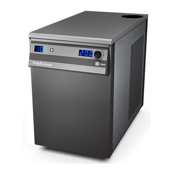
- Page 1 Operator’s Manual Model 4100 and 4200 Series Liquid-to-Liquid Coolers 110-497 09 March 2020...
-
Page 2: Table Of Contents
Table of Contents Introduction ................................3 General Safety Information .............................3 Safety Recommendations ............................4 Unpacking Your Liquid-to-Liquid Cooler .........................4 Regulatory and Compliance Testing ........................4 Contents ..................................4 Controls and Components ............................5 Front Control Panel ..............................5 Rear Panel ................................5 Installation and Startup ............................6 Site Requirements ..............................6 Ambient Temperature and Relative Humidity .....................6 Location ................................6 Clearance ................................6... - Page 3 Reservoir Fluids ..............................23 Replacement Parts ..............................24 PolyScience Fluids ..............................24 Optional Serial Output (RS-232) ........................... 25 Equipment Disposal (WEEE Directive) ........................ 26 Service and Technical Support ..........................26 Warranty ................................. 27 110-497...
-
Page 4: Introduction
Introduction Your Liquid-to-Liquid Cooler is a quiet and efficient heat removal system. Process cooling is provided by pumping facility water (or other liquid cooling medium) through a liquid-to-liquid brazed plate heat exchanger to cool the process fluid loop. Heat is rejected to the facility fluid and temperature controlled by a proportional valve that bypasses a portion of the process fluid around the heat exchanger. -
Page 5: Safety Recommendations
Safety Recommendations To prevent injury to personnel and/or damage to property, always follow your workplace’s safety procedures when operating this equipment. You should also comply with the following safety recommendations: WARNING: • Always connect the power cord on this unit to a grounded (3-prong) power outlet. Make certain that the outlet is the same voltage and frequency as your unit. -
Page 6: Controls And Components
Controls and Components Front Control Panel Pressure / Flow Rate Display Temperature Display Pressure / Flow Rate Units Select/Set Knob Power Button Units / Menu Select Button Temperature Units Rear Panel Reservoir Cap and Fluid Filter Port (top rear) Communication Port (optional Remote ON/OFF) Process Water Out... -
Page 7: Installation And Startup
Installation and Startup WARNING: Be sure all power is off before proceeding. Site Requirements Ambient Temperature and Relative Humidity The Liquid-to-Liquid Cooler is designed for indoor installation in ambient temperatures between 5° and 35°C (41° and 95°F); relative humidity should not exceed 80% (non-condensing). Location The Liquid-to-Liquid Cooler should be installed on a strong, level surface. -
Page 8: Process Fluid Connections
Process Fluid Connections Connect the process fluid inlet on the equipment to be cooled to the process fluid outlet on the Liquid-to-Liquid Cooler. Connect the process fluid outlet on the equipment to be cooled to the process fluid inlet on the Liquid Temperature. -
Page 9: Electrical Power
Electrical Power WARNING: Be sure that the electrical power supply is the same voltage and frequency as specified on the identification label. WARNING: DO NOT plug the Liquid-to-Liquid Cooler into the electrical outlet until the unit is ready for startup (see Startup). -
Page 10: Startup
Startup 1. Process Fluid • Connect the Liquid-to-Liquid Cooler to the process to be cooled with hoses or pipes. • Check hoses and fittings for tightness and make sure there are no crimps or bends in the hoses. 2. Facility Water Fluid •... -
Page 11: Normal Operation
Normal Operation Electrical Power Place the Circuit Breaker/Power Switch on the rear of the instrument enclosure in the “ON” position. Three decimal points will appear on the Temperature display; two decimal points will appear on the Pressure/Flow Rate display..Press the Power Button on the Controller’s front panel. -
Page 12: Setting Operational Parameters
Setting Operational Parameters The Liquid-to-Liquid Cooler’s operational parameters can be accessed by pressing and holding the Units/Menu Button until HL appears on the pressure/flow rate display. Pressing and releasing the Units/Menu Button once HL appears allows you to scroll through the various parameters. The displayed parameter is changed by rotating the Select/Set Knob until the desired value is displayed. -
Page 13: High Ambient Temperature Limit (Ha)
High Ambient Temperature Limit (HA) NOTE: This value is always set in °C. This menu item protects the unit from overheating due to a high ambient temperature. Should the ambient temperature rise above the limit value, the audio and visual alarms will activate and the pump will turn OFF. To change the high ambient temperature value, rotate the Select/Set Knob until the desired value is displayed on the temperature readout. -
Page 14: Calibration Offset (°C)
Calibration Offset ( °C ) CAUTION: To prevent the operator from accidentally changing the calibration offset, a special keystroke sequence is required to access this function. This menu item allows you to adjust the Liquid-to-Liquid Cooler’s temperature reading to match that of a traceable standard. -
Page 15: Baud Rate (Pc)
Baud Rate (PC) This menu item allows you to establish the baud rate for serial communication. Allowable settings are 0 (no serial communication), 24 (2400 baud), 48 (4800 baud), 96 (9600 baud), 192 (19200 baud). To change the displayed setting, rotate the Select/Set Knob until the desired baud rate is displayed. Press the Select/Set Knob or allow the display to time out to accept the displayed value. -
Page 16: Display, Alarm And Error Messages
Display, Alarm and Error Messages When certain conditions are detected, a message code flashes on the display and the local audio alarm sounds. Depending on the nature of the condition, power to various system components, such as the heater and pump, is removed. - Page 17 Fault Code Description Action Required Alarm — Process fluid temperature has dropped to low temperature Low temperature alarm limit value. Pump is turned OFF. (signaled if <16°C / 60.8°F for 5 seconds) Increase heat load or decrease low temperature limit value. Alarm —...
-
Page 18: Enabling / Disabling The Local Lockout
Enabling / Disabling the Local Lockout This feature is used to prevent unauthorized or accidental changes to set point and other operational values. When enabled, these values can be viewed but not changed. To enable the local lockout, press and hold the Select/Set Knob until LLO is displayed (approximately 5 seconds). Once enabled, LLO will appear momentarily when the Select/Set Knob is pressed to display the set point. -
Page 19: Routine Maintenance And Troubleshooting
Routine Maintenance and Troubleshooting WARNING: Hazardous voltages are present. Turn all power to the unit OFF and unplug the power cord from the electrical outlet when servicing unit. If electrical power is required (such as when measuring voltages across a live circuit), use extreme care when servicing the unit. WARNING: Refer servicing to qualified service personnel. -
Page 20: Draining The Unit
Draining the Unit CAUTION: To ensure that internal damage does not occur during shipping or storage, water must be drained from all parts of the system and an antifreeze solution of technical grade ethylene glycol or propylene glycol added. WARNING: Be sure to follow all appropriate safety and environmental guidelines when collecting and disposing of spent coolant. -
Page 21: Technical Information
Technical Information Performance Specifications 4100 Series Models 4200 Series Models Operating Temperature: 5° to 50°C / 41° to 122°F Temperature Stability: ±0.4°C / ±0.7°F Temperature Units: °C or °F Cooling Capacity @ 30°C: 10,000 watts 20,000 watts 34,100 BTU/hr 68,200 BTU/hr Reservoir Size: 1.1 gal / 4.16 liters... -
Page 22: Cooling Capacity Vs. Facility Water Flow Rate
Cooling Capacity vs. Facility Water Flow Rate The following graph is applicable to both 4100 and 4200 Series Liquid-to-Liquid Coolers. NOTE: Graph shows performance with full flow to process (no bypass). Facility water pressure drop through unit is 5 psi / 34.5 kPa at 16 GPM / 60.8 LPM. Facility water supply temperature is shown at 5°C, 10°C and 15°C below process temperature. -
Page 23: Wiring And Flow Diagram
Wiring and Flow Diagram 110-497... -
Page 24: Reservoir Fluids
Reservoir Fluids Specific Heat Normal Extreme Fluid Description Temperature Temperature @ Fluid BTU/lb°F KJ/Kg°C Range Range Temperature Distilled water 50°C 1.00 4.18 10° to 90°C 2° to 100°C Ethylene glycol -20°C 0.78 3.26 -25° to 100°C -30° to 115°C (50/50 mix with distilled H Ethylene glycol 0°C 0.89... -
Page 25: Replacement Parts
Reservoir Low Liquid Level Switch 525-550 Bypass Valve 750-175 3-way Proportional Valve 775-513 Heat Exchanger 750-193 PolyScience Fluids Circulating Bath Fluids Quantity Part Number polyclean CLARIFIER 8 oz / 236 ml 004-300040 polyclean CLARIFIER Twelve 8 oz / 236 ml bottles... -
Page 26: Optional Serial Output (Rs-232)
Optional Serial Output (RS-232) Serial Connector — A 9-pin D-connector (optional) is provided on the back panel of the Liquid-to-Liquid Cooler for RS-232 data communication. A serial cable that uses only the following pins should be used to connect the unit to the computer: Pin #2 —... -
Page 27: Equipment Disposal (Weee Directive)
Equipment Disposal (WEEE Directive) This equipment is marked with the crossed out wheeled bin symbol to indicate it is covered by the Waste Electrical and Electronic Equipment (WEEE) Directive and is not to be disposed of as unsorted municipal waste. Any products marked with this symbol must be collected separately, according to the regulatory guidelines in your area. -
Page 28: Warranty
This warranty gives you specific legal rights and you may have other rights that vary from state to state. Manufactured by: PolyScience 6600 W. Touhy Avenue Niles, IL 60714 U.S.A. 1-800-229-7569 ● 1-847-647-0611 www.polyscience.com...
Need help?
Do you have a question about the 4100 Series and is the answer not in the manual?
Questions and answers