Nord Drivesystems B1000 Series Operating And Maintenance Instructions Manual
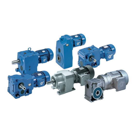
Gear units and geared motors
Hide thumbs
Also See for B1000 Series:
- Operating and assembly instructions manual (80 pages) ,
- Manual with installation instructions (80 pages)

Related Manuals for Nord Drivesystems B1000 Series

Summary of Contents for Nord Drivesystems B1000 Series
- Page 1 Intelligent Drivesystems, Worldwide Services B1000 Operating and Maintenance Instructions for DRIVESYSTEMS Gear Units and Geared Motors...
-
Page 3: Table Of Contents
Contents 1. Notes ............................. 4 1.1 General information ......................4 1.2 Safety and information symbols..................4 1.3 Correct use......................... 4 1.4 Safety information ......................5 1.5 Other documents ....................... 6 1.6 Disposal ..........................6 2. Description of gear units..................... 7 2.1 Type designations and gear unit types ................ -
Page 4: Notes
1. Notes 1. Notes 1.1 General information Read the Operating Manual carefully prior to performing any work on or putting the gear unit into operation. Strict compliance with the instructions in this Operating Manual is essential. Getriebebau NORD accepts no liability for damage to persons, materials or assets as a result of the non-observance of this Operating Manual, operating errors or incorrect use. -
Page 5: Safety Information
1. Notes 1.4 Safety information All work including transportation, storage, installation, electrical connection, commissioning, servicing, maintenance and repair must be performed only by qualified specialist personnel. It is recommended that repairs to NORD Products are carried out by the NORD Service department. -
Page 6: Other Documents
1. Notes 1.5 Other documents Further information may be obtained from the following documents: - Gear unit catalogues (G1000, G2000, G1011, G1012, G1034, G1035) - Operating and maintenance instructions for the electric motor - Operating instructions for attached options, if applicable 1.6 Disposal Observe the current local regulations. -
Page 7: Description Of Gear Units
2. Description of Gear Units 2. Description of gear units 2.1 Type designations and gear unit types Versions / Options Helical gear units SK 11E, SK 21E, SK 31E,SK 41E, SK 51E (single-stage) Foot mounting with solid shaft SK 02, SK 12, SK 22, SK 32, SK 42, SK 52, SK 62N Hollow shaft version (2-stage) Solid shaft version... -
Page 8: Type Plate
2. Description of Gear Units 2.2 Type plate Explanation of the Rating Plate NORD gear unit type Serial number Overall gear unit ratio Rated speed of gear unit drive shaft B1000 www.nord.com... -
Page 9: Storage, Preparation, Installation
3. Storage, Preparation, Installation 3. Storage, preparation, installation Storing the gear unit For short-term storage before commissioning, please observe the following: Store in the fitting position (see Section 6.1) and secure gear units against falling Lightly grease bare metal housing surfaces and shafts ... -
Page 10: Preparing For Installation
3. Storage, Preparation, Installation 3.3 Preparing for installation The drive unit must be inspected and may only be installed if no transportation damage or leaks are visible. In particular the radial seals and the sealing caps must be inspected for damage. In applications where an incorrect rotational direction may result in damage or potential risk, the correct rotational direction of the drive shaft is to be established by test running the drive when uncoupled and guaranteeing such for subsequent operation. -
Page 11: Installing The Gear Unit
3. Storage, Preparation, Installation 3.4 Installing the gear unit The eyebolts screwed into the gear units must be used during installation. The safety notes in Section 1.4 must be observed. The base and/or flange to which the gear unit is fitted should be vibration-free, torsionally strong and flat. -
Page 12: Fitting Hubs On The Gear Shafts
3. Storage, Preparation, Installation 3.5 Fitting hubs on the gear shafts Attention! Do not subject the gear unit to harmful axial forces when fitting the hubs. Drive and driven elements, e.g. coupling and chain-wheel hubs must be mounted onto the drive and driven shaft of the gear unit using suitable pullers that will not apply damaging axial forces onto the gear unit. - Page 13 3. Storage, Preparation, Installation Figure 3-4: Applying lubricant to the shaft and the hub Note! The gear unit can be fitted to shafts with and without a shoulder using the fastening element (Option B). Tighten the bolt of the fastening element to the correct torque. (See Chapter 6.2 for torque values) Figure 3-5: Gear unit mounted to shaft with a shoulder using the fastening element Figure 3-6: Gear unit mounted to shaft without a shoulder using the fastening element...
- Page 14 3. Storage, Preparation, Installation Figure 3-8: Mounting the rubber buffer (Option G and/or VG) on parallel shaft gear units Always support torque support on both sides! Figure 3-9: Attaching the torque support on bevel gear and worm gear units Tighten the bolts on the rubber buffer and the torque support to the correct torque (see Section 6.2 for torque values) and secure to prevent loosening (e.g.
-
Page 15: Fitting Shrink Discs
3. Storage, Preparation, Installation 3.7 Fitting shrink discs Shrink disc type, Mat. No. Solid shaft of machine Tensioning flanges and torque details for tensioning screws Shaft and and hollow shaft bore GREASE FREE! Tensioning screws DIN 931 (933) -10.9 The shrink discs are suplied by the Hollow shaft of gear unit manufacturer ready for fitting. -
Page 16: Fitting The Covers
3. Storage, Preparation, Installation 10. When the tensioning bolts have been tightened, there must be an even gap between the clamping flanges. If this is not the case, the gear unit must be dismantled and the shrink disc connection checked for correct fit. Danger! Risk of injury from incorrect mounting and dismantling of the shrink disc. - Page 17 3. Storage, Preparation, Installation Assembly procedure to attach a standard motor to the IEC adapter (Option IEC)/NEMA adapter 1. Clean motor shaft and flange surfaces of motor and adapter and check for damage. Mounting dimensions and tolerances of the motor must conform to DIN EN 50347/NEMA MG1 Part 4.
-
Page 18: Retrospective Paintwork
3. Storage, Preparation, Installation Gear coupling (BoWex ), one-part Gear coupling (BoWex ), two-part Gear coupling (BoWex ), two-part with spacer bush Claw coupling (ROTEX ), two-part Claw coupling (ROTEX ), two-part, observe dimension B: Standard helical gear unit: SK0, SK01, SK20, SK25, SK30, SK33 (2-stage) SK010, SK200, SK250, SK300, SK330 (3-stage) -
Page 19: Commissioning
4. Commissioning 4. Commissioning 4.1 Checking the oil level The oil level must be checked prior to commissioning. See Section 5.2. 4.2 Activating the automatic lubricant dispenser Some gear unit types with standard motor (Option IEC/NEMA) have an automatic lubricant dispenser for the rolling bearings. -
Page 20: Operation With Lubricant Cooling
4. Commissioning 4.3 Operation with lubricant cooling Water cooling Caution! The drive may only be commissioned after the cooling spiral has been connected to the cooling circuit, and the cooling circuit has been put into operation. The coolant must have a similar thermal capacity as water (specific thermal capacity at 20°C c=4.18 kJ/kgK). -
Page 21: Service And Maintenance
5. Service and Maintenance 5. Service and maintenance 5.1 Service and maintenance intervals Information – Service and Maintenance Intervals Service and Maintenance Work see Section At least every six months -Visual inspection - Check for running noises – Check oil level –... - Page 22 5. Service and Maintenance Checking the oil level: 1. The oil level may only be checked when the gear unit is at a standstill and has cooled down. The gear unit must be secured to prevent accidental switch-on. 2. The oil level screw corresponding to the version must be screwed out. (See Section 6.1) Note! At the first oil level check a small amount of oil may escape, as the oil level may be below the lower edge of the oil level hole.
- Page 23 5. Service and Maintenance Danger! Warning: Hot oil! Drain all the oil from the gear unit. If the screw lock coating of the oil drain screw or oil level screw is damaged in the thread, a new oil level screw must be used or the thread cleaned and coated with securing lubricant, e.g.
-
Page 24: Appendix
6. Appendix Versions and maintenance Explanation of symbols for the following version illustrations: Vent Oil level Oil drain Note! SK 320, SK 172, SK 272, SK 372K, SK 273 and SK373 as well as SK 01282 NB, SK 0282 NB, SK 1382 NB and UNIVERSAL / Minibloc gear units are lubricated for life. These gear units do not have an oil filler screw. - Page 25 B3+B5 B3+B5 V6+V3 V6+V3 B7+B5III B7+B5III SK 02 SK 11E SK 12 SK 21E SK 22 SK 31E SK 32 SK 41E SK 42 SK 51E SK 52 SK 62N B6+B5II B6+B5II V5+V1 V5+V1 B8+B5I B8+B5I B3+B5 B3+B5 B7+B5III V6+V3 B7+B5III V6+V3 SK 62...
- Page 26 B3+B5 V3+V6 B7+B5III SK 372.1 SK 472 SK 572.1 SK 572 SK 672.1 SK 672 SK 373.1 SK 772 SK 573.1 SK 872 SK 673.1 SK 972 SK 473 SK 573 SK 673 SK 773 SK 873* SK 973* B6+B5II V1+V5 B8+B5I SK 372.1F...
- Page 27 SK 772.1F SK 872.1F SK 972.1F SK 773.1F* SK 873.1F* SK 973.1F* SK 072.1 F SK 072.1 SK 172.1 F SK 172.1 40 www.nord.com B1000 -27-...
- Page 28 B3+B5 V6+V3 SK 0 SK 01 SK 20 SK 25 SK 30 SK 33 B7+B5III V1+V5 B6+B5II B8+B5I B3+B5 V6+V3 SK 010 SK 200 SK 250 SK 300 SK 330 B7+B5III B6+B5II V1+V5 B8+B5I 41 -28- B1000 www.nord.com...
- Page 29 SK 1282 SK 2382 SK 3382 SK 2282 SK 4382 SK 3282 SK 4282 SK 5382 SK 5282 SK 0182NB∗ SK 0282NB∗ SK 1382NB* * 24 SK 6282* SK 7282* SK 8282* SK 9282* SK 10282* SK 11282* SK 6382 SK 7382 SK 8382...
- Page 30 SK 92172 SK 92372 SK 92072 SK 92672 SK 92772 SK 9012.1 SK 9013.1 SK 9016.1 SK 9017.1 SK 9022.1 SK 9023.1 SK 9032.1 SK 9033.1 SK 9042.1 SK 9043.1 SK 9052.1 SK 9053.1 SK 9062.1 SK 9072.1 SK 9082.1 SK 9086.1 SK 9092.1 SK 9096.1...
- Page 31 H1+B5I H1+B5I H6+V3 H4+B5 H4+B5 H6+V3 SK 92172 SK 92372 SK 92072 SK 92672 SK 92772 H5+V1 H5+V1 H3+B5II H3+B5II H2+B5III H2+B5III H1+B5I H1+B5I H6+V3 H4+B5 H4+B5 H6+V3 SK 9012.1 SK 9013.1 SK 9016.1 SK 9017.1 SK 9022.1 SK 9023.1 SK 9032.1 SK 9033.1 SK 9042.1...
- Page 32 SK 02050 SK 13050 SK 12063 SK 13063 SK 12080 SK 13080 SK 32100 SK 33100 SK 42125 SK 43125 H1+B5I H1+B5I H4+B5 H6+V3 H4+B5 H6+V3 SK 02050 SK 13050 SK 12063 SK 13063 SK 12080 SK 13080 SK 32100 SK 33100 SK 42125 SK 43125...
- Page 33 SK 02040 H1+B5I H6+V3 SK 02040 H4+B5 H3+B5II H5+V1 H2+B5III www.nord.com B1000 -33-...
- Page 34 SK 1SI31 – SK 1SI75 SK 1SIS31 – SK 1SIS75 SK 1SIS-D31 – SK 1SIS-D63 SK 2SIS-D40 – SK 2SIS-D63 SK 1S32 - SK 1S63 SK 2S32NB – SK 2S63NB SK 1SU32 – SK 1SU63 SK 2SU32NB- SK 2SU63NB SK 1SM31 – SK 1SM63 SK 2SM40 –...
-
Page 35: Torque Values
6.2 Torque values Bolt Torques [Nm] Size Screw connections in the strength classes Sealing Threaded pin 10.9 12.9 screws on coupling 1150 1300 1600 2250 2650 2780 3910 4710 4470 6290 7540 G1¼ 6.3 Troubleshooting Gear unit malfunctions Fault Possible cause Remedy Oil too low or Unusual running noises,... -
Page 36: Lubricants
6.4 Lubricants With the exception of type SK 11282, SK 11382 and SK 12382 gear units, all gear units are filled with lubricant ready for operation in the required installation position when delivered. This initial filling corresponds to a lubricant from the column for the ambient temperatures (normal version) in the lubricant table. - Page 37 Lubricant table This table shows comparable lubricants from various manufacturers. The manufacturer can be changed within a particular viscosity or lubricant type. Getriebebau NORD must be contacted in case of change of viscosity or lubricant type, as otherwise no warranty for the functionality of our gearboxes can be accepted.
-
Page 38: Lubricant Quantities
6.5 Lubricant quantities Note! After changing the lubricant, and in particular after the initial filling, the oil level may change during the first few hours of operation, as the oil galleries and hollow spaces only fill gradually during operation. The oil level is still within the permissible tolerance. If at the express request of the customer, an oil inspection glass is installed at an additional charge, we recommend that the customer corrects the oil level after an operating period of approx. - Page 39 6.1 B5II B5III 6.1 SK11E 0,25 0,50 0,55 0,40 0,35 0,35 0,30 0,35 0,50 0,30 0,40 0,40 0,60 1,20 1,20 1,00 1,00 1,00 0,50 1,40 1,10 0,70 0,90 0,90 SK21E SK31E 1,10 2,70 2,20 2,30 1,70 1,70 0,80 1,30 1,65 1,10...
- Page 40 6.1 6.1 0,16 0,32 0,21 0,23 0,18 0,20 0,16 0,32 0,21 0,23 0,18 0,20 SK072.1 SK072.1 F SK172.1 0,27 0,59 0,42 0,45 0,32 0,39 SK172.1 F 0,27 0,59 0,42 0,45 0,32 0,39 0,45 1,05 0,75 1,00 0,60 0,65 0,45 1,05 0,75...
- Page 41 M1 M2 M3 M4 M5 M1 M2 M3 M4 M5 6.1 6.1 B3 V6 B8 V5 B5 V3 B5I V1 B5II B5III 0,13 0,22 0,13 0,22 0,13 0,13 SK0 F 0,13 0,22 0,13 0,22 0,13 0,13 0,22 0,38 0,22 0,38 0,22 0,22 0,22 0,38 0,22 0,38 0,22 0,22...
- Page 42 6.1 B5III B5II 6.1 SK92072 0,40 0,60 0,50 0,50 0,40 0,40 0,40 0,60 0,50 0,50 0,40 0,40 0,55 0,90 0,95 1,10 0,75 0,62 0,50 0,92 0,87 1,05 0,75 0,65 SK92172 0,90 1,30 1,45 1,60 1,20 1,20 1,15 1,50 1,20 1,70 1,15...
-
Page 43: List Of Addresses
M5 M6 M5 M6 6.1 V5 V6 B5 B5III B5II V1 V3 6.1 H5 H6 6.1 SK02040 0,45 0,60 0,60 0,60 0,50 0,50 SK02040 A 0,40 0,80 0,65 0,60 0,50 0,50 0,40 1,20 0,70 1,15 0,70 0,70 SK02050 A 0,45 1,10 0,90 1,10 0,80 0,80... - Page 44 Getriebebau NORD national: Niederlassung Nord Getriebebau NORD GmbH & Co. KG Tel.: +49(0) 4532 / 401-0 Hamburg / Schleswig-Holstein / Postfach 12 62 · 22943 Bargteheide Fax: +49(0) 4532 / 401-253 Niedersachsen Rudolf-Diesel-Straße 1 · 22941 Bargteheide E-mail: info@nord-de.com Vertriebsbüro Bremen Getriebebau NORD GmbH &...
- Page 45 MX – 66266 Mexico, C.P. Tel.: +43-732-31 89 20 Fax: +43-732-31 89 20-85 Tel.: +52-81-82 20 91 65 Fax: +52-81-82 20 90 44 info@nord-at.com HGonzales@nord-mx.com AUS NORD Drivesystems 18 Stoney Way NORD Aandrijvingen Nederland B.V. 3030 Derrimut Vic, Australia Voltstraat 12, NL-2181 HA Hillegom Tel: +61 (0) 488 588 200 Tel.: +31-252-52 95 44 Fax: +31-252-52 22 22...
- Page 48 Intelligent Drivesystems, Worldwide Services Getriebebau NORD GmbH & Co. KG Rudolf-Diesel-Str. 1 D - 22941 Bargteheide Fon +49 (0) 4532 / 401 - 0 Fax +49 (0) 4532 / 401 - 253 info@nord.com DRIVESYSTEMS www.nord.com...
Need help?
Do you have a question about the B1000 Series and is the answer not in the manual?
Questions and answers