Table of Contents
Advertisement
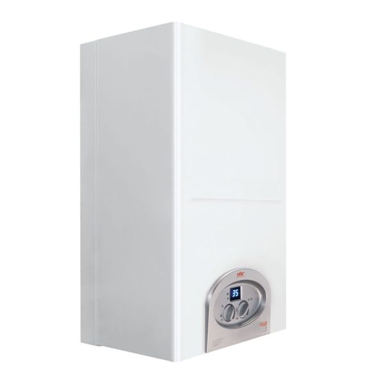
The Astro Range of Boilers
the ultimate solution for central heating & hot water
INSTALLATION
&
TECHNICAL MANUAL
If you require any further assistance:
Telephone: 01698 820533
Fax:
01698 825697
E-mail: info@electric-heatingcompany.co.uk
or visit our website www.electric-heatingcompany.co.uk
rev.no:04
27.09.2019
Advertisement
Table of Contents

Related Manuals for EHC Fusion Astro Series


Summary of Contents for EHC Fusion Astro Series
- Page 1 The Astro Range of Boilers the ultimate solution for central heating & hot water INSTALLATION & TECHNICAL MANUAL If you require any further assistance: Telephone: 01698 820533 Fax: 01698 825697 E-mail: info@electric-heatingcompany.co.uk or visit our website www.electric-heatingcompany.co.uk rev.no:04 27.09.2019...
-
Page 3: Table Of Contents
CONTENT 1. SAFETY Page 1 Page 1 1.1 SYMBOL KEY 1.2 SAFETY PRECAUTIONS Page 1 1.3 GENERAL EXPLANATIONS Page 2 1.4 INSTRUCTIONS AND BUILDING REGULATIONS Page 2 1.5 C.O.S.H.H Page 3 1.6 PREPARATION Page 3 1.6.1 Load Check Page 3 1.6.2 Boiler Location Page 3 1.6.3 Central Heating Installation... - Page 4 Page 20 4. COMMISSIONING 4.1 FILLING WATER TO THE SYSTEM Page 20 4.2 STARTING UP Page 21 Page 22 5. USER INSTRUCTIONS Page 22 5.1 CONTROL PANEL Page 23 5.2 ERROR CODES Page 24 TROUBLE SHOOTING Page 25 PRODUCT SAFETY Page 25 6.1 BUILT-IN RCD DEVICE (SHORT CIRCUIT RELAY) Page 25...
-
Page 5: Safety
This appliance is not intended for use by persons (including children) with reduced physical, sensory or mental capabilities or lack of experience and knowledge unless they have been given supervision or instruction concerning the use of the appliance by a person responsible for their safety. Children should be supervised to ensure that they do not play with the appliance. -
Page 6: General Explanations
Regulations, Building Regulations, Water Fitting Regulations (England & Wales) or Water By-laws (Scotland) and all relevant British Standards. EHC will not be not responsible for damages caused from improper installation and incorrect use of the appliance. Make sure the boiler is operated as intended. Any use which does not comply with the boiler's intended purpose may cause serious injury, death or harm to the environment and the appliance. -
Page 7: Preparation
1.5 C.O.S.H.H Materials used in the manufacture of this appliance are non-hazardous and no special precautions are required when fitting or servicing this appliance. 1.6 PREPARATION 1.6.1 Load Check A load check should be taken into consideration when installing high output boilers. 1.6.2 Boiler Location The boiler must be installed onto a wall that will provide an adequate fixing and within an area that is not subject to frost or damp conditions. -
Page 8: Components Of The Boiler
2.2 BOILER COMPONENTS a. Main heat exchanger n. PCB Control board o. Cooling fan b. Heating elements c. Actuator Valve p. Electric terminal d. Flow manifold q. CH - NTC sensor r. Short-circuit thermostat e. DHW temperature NTC sensor f. Pressure switch s. -
Page 9: Main Features Of The Boiler
2.3 MAIN FEATURES OF THE BOILER EHC Fusion Astro electric combination boilers provide central heating by connecting to panel radiators or underfloor heating systems. The primary circuit is heated via the main heat exchanger within the boiler and circulated throughout the system by the smart modulating pump. -
Page 10: Mounting And Installation
3.MOUNTING AND INSTALLATION 3.1 OPENING THE BOX Open the box as above . Cut the cord or remove the staples, fold the box shown lids backward and turn the box upside down onto a protected surface. Pull the box upwards and remove. Note: Care must be taken when opening and 3.1.1 Delivery Content removing the boiler from its packaging to... -
Page 11: Minimum Spaces For Installation
3.3 MINIMUM CLEARANCES 400mm 60mm 60mm 450mm 200mm 3.4 WALL MOUNTING Hold the mounting plate against the wall at your chosen height parallel to the floor taking into consideration the minimum required clearances and level with a spirit level. Mark the holes. Drill and insert the provided wall plugs. -
Page 12: Heating And Dhw System Installation Connections
HEATING AND HOT WATER CONNECTIONS • Cold & Hot Water Connections. The cold water inlet and hot water outlet connections are G 1/2" male thread connections. Use 2 x 1/2" female to 15mm pipe adapters with an isolation valve fitted to the cold supply connection. - Page 13 • Connections • Flushing. • The primary circuit must be flushed in accordance to BS 7593. The system must be flushed to within 10% off mains water PPM to ensure that no debris is trapped in the system. • Failure to do so may lead to boiler failure which will not be covered by manufacturer's warranty.
-
Page 14: Boiler Installation Schematics
• or and as per the instruction • We recommend F1 Protector and F3 Cleaner for our systems. If you 03301007750 or Technical 0870 870 0362 or further assistance. 3.5.1 BOILER INSTALLATION SCHEMATICS... -
Page 15: Circulation Pump Imformation
3.5.2 CIRCULATION PUMP IMFORMATION Indicator Lights (Leds) • Signal display • LED is lit up in green in normal operation • LED lights up/flashes in case of fault • Display of selected control mode Δp-v, Δp-c and constant speed • Display of selected pump curve (I, II, III) within the control mode •... - Page 16 Control modes and functions Variable differential pressure Δp-v (I, II, III) Recommended for two-pipe heating systems with radi- ators to reduce the flow noise at thermostatic valves. The pump reduces the delivery head to half in the case of decreasing volume flow in the pipe network. Electrical energy saving by adjusting the delivery head to the volume flow requirement and lower flow rates.
- Page 17 Control modes and functions...
-
Page 18: Electrical Connections
3.6 ELECTRICAL CONNECTIONS All electricity connections to the boiler must be made by a fully quailified electrician. Improper electric connections made by unqualified people may cause failure of critical components of the boiler and will invalidate the warranty. DANGER ! Electric Shock Risk ... - Page 19 3.6.3 Electrical Supply Connections The main electricity supply connection must be made according to the minimum cable sizes indicated on the boiler technical label. The connections are made to the RCD device according to the diagram below. Single Phase N L1 L2 L3 3-Phase The cable connections are clearly marked on the cables connected to the RCD device.
-
Page 20: Electrical Connection Diagram 230V (Single Phase)
3.6.4 Electrical Connection Diagram 230V (Single Phase) MAIN BOARD L N N L RELAY BOARD... -
Page 21: Electrical Connection Diagram 400V (3-Phase)
3.6.5 Electrical Connection Diagram 400V (3-phase) MAIN BOARD L N N L RELAY BOARD... -
Page 22: Main Pcb Dip Switches
3.7 MAIN PCB DIP SWITCH SETTINGS The universal main board of the boiler is designed to be suitable for all types of Fusion Astro boilers. Make sure to adjust the switch positions on the main board according to the boiler type while replacing the mainboard in case of a failure. The switch positions are explained below. -
Page 23: Room Thermostat Connection
This is where your Volt Free external control cable should be connected. Remember to remove the link before connecting your external Volt Free control cables. We recommend using an EHC single channel heat pack that includes a wired programmer and room thermostat, alternatively a wireless thermostat can be used. -
Page 24: Commissioning
4. COMMISSIONING 4.1 FILLING THE SYSTEM a) Connect the primary filling loop and tighten. b) Make sure that all primary connections are tight before filling. c) Loosen the automatic air vent on the pump body. d) Open all thermostatic valves on the radiators. e) Fill the system to 1,5 bar and vent. -
Page 25: Starting Up
d) Drain and flush the system thoroughly to remove the cleaning agent and any debris or contaminants. This is a critical part of the cleaning process and must be carried out correctly. Use a rinse test meter (TDS) , such as the Fernox CTM. The reading must be within 10% of the mains ppm value. -
Page 26: User Instructions
5. USER INSTRUCTIONS 5.1 CONTROL PANEL All boiler functions are adjusted from the front control panel. A. P1 KEY Select this icon when there is a requirement for instant hot water. Turning the A-P1 dial clockwise will adjust the HW temperature. Once you have selected your required temperature, the LCD screen (C) will automatically revert back to the actual water temperature being provided at that time. -
Page 27: Error Codes
C. DIGITAL SCREEN Operating parameters and errors codes. a) Heating Capacity Indicators: Shows which heating elements are in operation, indicating the modulation level of the boiler. b) Heating Mode Indicator: The dash position on the display shows whether the boiler is operating in CH or DHW mode. -
Page 28: Troubleshooting
5.3 TROUBLESHOOTING... -
Page 29: Product Safety
6. SAFETY SYSTEM EHC Fusion Astro Electric Combi Boilers have the following safety features to ensure the highest level of safety is achieved. 6.1 INTERNAL RCD DEVICE (SHORT CIRCUIT RELAY) In case of short circuit, the relay shuts off the electrical power supply to the boiler preventing any possibility of electrocution. -
Page 30: Frost Protection
6.6 FROST PROTECTION If the temperature within the heating system drops below 5°C, there is security system will automatically activate the boiler. When the water temperature within the heat exchanger reaches 40°C the activation is stopped. In order for this system work the heating and hot water selector switches must be set to the minimum setting. -
Page 31: Technical Table
7. TECHNICAL TABLE Capacity Heating Power Output 40945 51182 61418 81891 Maximum Working Pressure (Heating) Internal Expansion Vessel Maximum Working Pressure (DHW) Heating Circuit Temperature Range °C 30-80 30-80 30-80 30-80 Hot Water Temperature Range °C 30-55 30-55 30-55 30-55 Hot Water Output (ΔT= 30°C) L/min Dimentions... -
Page 32: Maintenance
9. GUARANTEE CONDITIONS The boiler comes with a standard 24 months warranty. Warranty registrations must be completed and returned to EHC. If boilers are not registered the warranty on the boiler will start from the date of purchase. Boilers must be installed by a fully qualified engineer and commissioned as per the instructions within this manual. -
Page 33: Exploded View
10. EXPLODED VIEW... -
Page 34: Main Heat Exchanger Group Detail
10.1 MAIN HEAT EXCHANGER GROUP DETAIL... -
Page 35: Hydrolic Group Detail
10.2 HYDROLIC GROUP DETAIL... -
Page 36: Relay Board Group Detail
10.3 RELAY BOARD GROUP DETAIL � - ıf ,. I""\ - �... -
Page 37: Exploded View Parts List
10.4 EXPLODED VIEW PARTS LIST 1. Plastic frame 39. Limit thermostat 40. Short-circuit thermostat 2. Control buttons 3. Control panel 41. CH temperature NTC sensor 4. Mainboard 42. Copper return pipe 5. Control panel rear cover 43. R 3/4” flow outlet 44. - Page 38 (Waste Electrical & Electronic Equipment) (applicable in the European union and other European countries with separate collection systems). This marking shown on the product or its literature, indicates that it should not be disposed of with other household wastes at the end of its working life. To prevent possible harm to the environment or human health from uncontrolled waste dis-posal, please separate this from other types of wastes and recycle it responsibly to promote the sustainable reuse of material resources.
Need help?
Do you have a question about the Fusion Astro Series and is the answer not in the manual?
Questions and answers
Hello I need help please
Ive turned my water pressrure up to high