Table of Contents
Advertisement
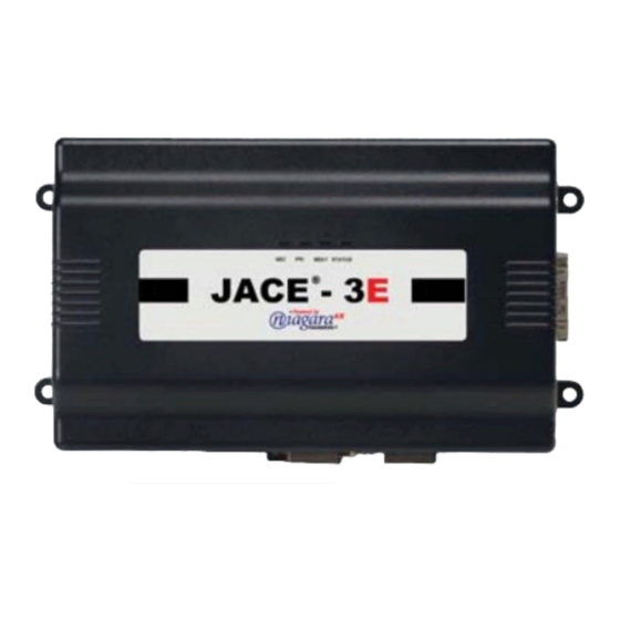
NETWORK CONTROLLER 3E & 6E
14
MOUNTING AND WIRING GUIDE
T he J A C E- 3E a n d J A CE - 6 E co n trol l er s
a re c om p a c t, e m b ed d ed
c o ntro ll er /ser ve r p l at fo r ms t hat al lo w
i nt eg r a t e d c o n t ro l a n d m a n a g e m e n t o f
e xt er na l d ev ic es ov er t h e I nt er net .
Th e J A CE - 3 E u se s a P ow e r P C 40 5
4 0 0 M h z p ro c e s s o r ; t h e J AC E -6 E u se s a
P o we rP C 4 40 524 Mhz proce ssor.
E a ch c on trol l er s up p o rt s t wo o p ti o na l
c o m mu ni c a ti o ns c a rds a s w el l a s
op t io n al I/O ex p a ns io n mo d u le s.
O n b o a rd s ta t ic R A M ( S R A M ) p ro v id e s
N i a ga ra A X s ta t io n b a ck u p c a p a b il i t y
w i t ho u t a n y b a t te ry in s ta l l ed . A n
o p t io na l b a c k up b a tt er y i s a l s o
Part Number 12762 Rev 1.1
a v a il a b l e .
April 30, 2014
|
INSTALL GUIDE
Advertisement
Table of Contents

Subscribe to Our Youtube Channel
Related Manuals for Niagara JACE-3E


Summary of Contents for Niagara JACE-3E
- Page 1 INSTALL GUIDE NETWORK CONTROLLER 3E & 6E MOUNTING AND WIRING GUIDE T he J A C E- 3E a n d J A CE - 6 E co n trol l er s a re c om p a c t, e m b ed d ed c o ntro ll er /ser ve r p l at fo r ms t hat al lo w i nt eg r a t e d c o n t ro l a n d m a n a g e m e n t o f e xt er na l d ev ic es ov er t h e I nt er net .
-
Page 2: Table Of Contents
Tridium, Inc. Complete confidentiality, trademark, copyright and patent notifications can be found at: http://www.tridium.com/galleries/SignUp/Confidentiality.pd JACE, Niagara Framework, Niagara AX Framework and the Sedona Framework are trademarks of Tridium, Inc. NETWORK CONTROLLER 3E & 6E MOUNTING AND WIRING GUIDE... - Page 3 Part Number 12762 Rev 1.1 April 30, 2014 Status LEDs ..........25 Ethernet Ports .......................25 Heartbeat ......................25 Status ........................25 Serial Ports ......................25 Maintaining the Controller ......26 Cleaning ........................26 NiMH Battery Installation and Maintenance ............26 Replacement Parts ........28 Non-replaceable Parts ..................29 Standard Replacement Parts ................29 New Replacement Unit ..................29 Replacing the Controller Base Assembly ............29...
-
Page 4: About This Guide
Related Documentation About This Guide This document covers the mounting and wiring of the Tridium® JACE-3E (T-300E) and JACE-6E (T-600E) controllers. It assumes that you are an engineer, technician, or service person who is performing control system installation. Instructions in this... -
Page 5: Preparation
Material and Tools Required Included in this Package Included in this package you should find the following items: • A JACE-3E or JACE-6E controller. • This Network Controller 3E & 6E Mounting and Wiring Guide, Part Number 12762 Rev 1.1. -
Page 6: Precautions
Part Number 12762 Rev 1.1 April 30, 2014 PRECAUTIONS Safety Precautions Precautions This document uses the following warning and caution conventions: Caution Cautions remind the reader to be careful. They alert readers to situations where there is a chance that the reader might perform an action that cannot be undone, might receive unexpected results, or might lose data. -
Page 7: Battery Precautions
PRECAUTIONS Part Number 12762 Rev 1.1 April 30, 2014 Battery Precautions Battery Precautions Caution • The optional NiMH battery used in this device may present a risk of fire or chemical burn if mistreated. Do not disassemble, heat above 122ºF (50ºC), or incinerate. -
Page 8: Mounting
Part Number 12762 Rev 1.1 April 30, 2014 MOUNTING Environmental Requirements Mounting Before mounting the controller, install any option card(s). See “About Option Cards, ” page 11. Also see “RS-485 Biasing, ” page 20. Then mount the controller in a location that allows clearance for wiring, servicing, and module removal. - Page 9 MOUNTING Part Number 12762 Rev 1.1 April 30, 2014 Physical Mounting • Mounting on a 35mm wide DIN rail is recommended. The controller’s unit base has a molded DIN rail slot and locking clip, as do the power supply modules and both types of I/O expansion modules.
-
Page 10: Removing And Replacing The Cover
Part Number 12762 Rev 1.1 April 30, 2014 MOUNTING Removing and Replacing the Cover Step 2 Position the controller on the rail, tilting to hook DIN rail tabs over one edge of the DIN rail (Figure Step 3 Use a screwdriver to pry down the plastic locking clip, and push down and in on the unit, forcing the locking clip to snap over the other DIN rail edge. -
Page 11: About Expansion Options
ABOUT EXPANSION OPTIONS Part Number 12762 Rev 1.1 April 30, 2014 About Option Cards Figure 3 T-300E or T-600E controller main board layout details. Status LEDs (visible with cover on): Serial port LEDs on bottom Option Slot 2 board, remove cover to see: LAN1 BEAT LAN2... - Page 12 Part Number 12762 Rev 1.1 April 30, 2014 ABOUT EXPANSION OPTIONS About Option Cards Table 1 JACE-3E and JACE-6E Controller Option Cards. Option Description Notes NPB-2X-485 Dual, optically-isolated, RS-485 If installed in Option slot 1, ports operate adapter with two 3-position remov- as COM3 and COM4.
-
Page 13: About Accessory Modules
ABOUT EXPANSION OPTIONS Part Number 12762 Rev 1.1 April 30, 2014 About Accessory Modules Note If you are also installing the optional NiMH battery/bracket assembly now, remove and retain the other two screws, that is for the other option slot. Step 6 Carefully insert the pins of the option card into the socket headers of the option card slot. -
Page 14: Wiring Details
Part Number 12762 Rev 1.1 April 30, 2014 WIRING DETAILS About Accessory Modules Table 2 Accessory modules compatible with the T-300E and T-600E controller. Model Description Notes NPB-PWR DIN-mountable, 24V isolated Only one NPB-PWR per controller. power module, used to power •... -
Page 15: Grounding
WIRING DETAILS Part Number 12762 Rev 1.1 April 30, 2014 Grounding Grounding An earth ground spade lug (0.187") is provided on the controller base for connection to earth ground. For maximum protection from electrostatic discharge or other forms of EMI, connect the supplied earth grounding wire to this lug and a nearby earth ground. - Page 16 Part Number 12762 Rev 1.1 April 30, 2014 WIRING DETAILS Power Wiring Note If powering from a 24V transformer, do not power any other equipment with it. Otherwise, conducted noise problems may result. Also, do not ground either side of the transformer’s 24V secondary. Figure 4 NPB-PWR module wiring connections.
- Page 17 WIRING DETAILS Part Number 12762 Rev 1.1 April 30, 2014 Power Wiring Figure 5 NPB-PWR-UN module wiring connections. Remove cover 6-pin NOTE: The 6-pin connector on the connector NPB-PWR-UN is not used with a T-300E not used or T-600E series controller. The 6-pin connector is designed for use with other controllers or modules, and must be left unused.
-
Page 18: Communications Wiring
Part Number 12762 Rev 1.1 April 30, 2014 WIRING DETAILS Communications Wiring Caution Do not plug the barrel connect plug from the WPM-XXX into the controller until all other mounting and wiring is completed. See “Power Up and Initial Checkout, ” page 23. - Page 19 WIRING DETAILS Part Number 12762 Rev 1.1 April 30, 2014 Communications Wiring Serial There are two “RS” serial ports on the controller’s base board. Each has a UART capable of operation up to 115,200 baud. At the bottom of the board (see Figure 6) is RS-232...
-
Page 20: Rs-485 Biasing
Part Number 12762 Rev 1.1 April 30, 2014 WIRING DETAILS RS-485 Biasing RS-485 Biasing The RS-485 port on the controller’s base board has a pair of two-pin jumpers that can be shorted with jumper blocks to provide “biasing”. As shipped from the factory, these pins are not shorted, thus the RS-485 port is unbiased. - Page 21 WIRING DETAILS Part Number 12762 Rev 1.1 April 30, 2014 RS-485 Biasing Figure 7 Basic stages of controller disassembly. Cover removed, reveals metal shield Phillips head screws Metal shield lifted away NPM3E or NPM6E Processor module (board) Metal standoffs Processor module lifted away Jumper block for RS-485 biasing...
- Page 22 Part Number 12762 Rev 1.1 April 30, 2014 WIRING DETAILS RS-485 Biasing Figure 8 Install shorting blocks across both sides of jumper block to add RS-485 bias. Shorting blocks lifted away Shorting blocks Position of installed across pre-installed jumper pins shorting blocks (biasing added) (no biasing)
-
Page 23: Power Up And Initial Checkout
25, especially “Heartbeat”. About Backup Configurations A JACE-3E (T-300E) or JACE-6E series (T-600E) controller allows two separate and configurable methods to preserve unsaved station data when "power quality events" occur, including loss of primary power or low-voltage dips (brownout): •... -
Page 24: Sram
Part Number 12762 Rev 1.1 April 30, 2014 ABOUT BACKUP CONFIGURATIONS SRAM longer duration outages, the battery allows the controller to perform a “controlled shutdown”, safely backing up the station before shutting down. Starting in the AX-3.6.nn maintenance build, the JACE can use both the NiMH backup battery and available SRAM for backup protection (prior to this, SRAM support required removing backup batteries). -
Page 25: Status Leds
STATUS LEDS Part Number 12762 Rev 1.1 April 30, 2014 Ethernet Ports new NiMH battery may be partially discharged. Therefore, allow at least 18 hours for a new battery to charge if it has not been in a powered unit. The NiMH battery assembly should be replaced approximately every three years, or more often if the unit is in a high temperature environment. -
Page 26: Maintaining The Controller
Part Number 12762 Rev 1.1 April 30, 2014 MAINTAINING THE CONTROLLER Status Status The green “STATUS” LED is next to the heartbeat LED, and is visible on the cover. This LED provide a CPU machine status check, and should remain lit whenever the controller is powered. - Page 27 MAINTAINING THE CONTROLLER Part Number 12762 Rev 1.1 April 30, 2014 NiMH Battery Installation and Maintenance replace) the battery, you must remove power to the controller and remove its cover. Then you mount the battery assembly on top of the option card area (Figure Figure 9 Optional NiMH battery pack in T-300E or T-600E controller.
-
Page 28: Replacement Parts
Part Number 12762 Rev 1.1 April 30, 2014 REPLACEMENT PARTS NiMH Battery Installation and Maintenance Step 8 Set the new NiMH battery assembly on top of the option card slots, over the option card end plates. Ensure the bracket mounting holes are aligned with the standoffs. -
Page 29: Non-Replaceable Parts
REPLACEMENT PARTS Part Number 12762 Rev 1.1 April 30, 2014 Non-replaceable Parts Non-replaceable Parts Other than the parts listed in the replacement parts sections, there are no serviceable components on the base assembly. Memory Any addition, modification, or replacement of memory components requires software configuration and is not a field upgrade. - Page 30 Part Number 12762 Rev 1.1 April 30, 2014 REPLACEMENT PARTS Replacing the Controller Base Assembly To replace a controller with a new replacement unit, proceed as follows: Procedure 9 Replacing a T-300E or T-600E controller. Step 1 If possible, use the appropriate NiagaraAX software tool to back up the con- troller’s configuration to your PC.
-
Page 31: Returning A Defective Unit
• Nature of the defect • PO number to secure the RMA Certifications The JACE-3E (T-300E) and JACE-6E (T-600E) controller each has the following agency listings, compliances, and certifications: • UL 916 - Underwriters Laboratories, Energy Management Device, CAN/CSA C22.2 Canadian Safety Standards •... -
Page 32: Tab Mounting Dimensions
Measurements are in inches and (mm). Note that DIN mounting is recommended over tab mounting. See Figure 1 on page 9. 0.170" 6.72" (170.7) Dia. (4.32) JACE-3E or JACE-6E 3.75" (95.3) NOTE: Electronic and printed versions of this 2.5" 4.0" document may not show dimensions to scale. (63.5) (101.6) Verify all measurements before drilling.
Need help?
Do you have a question about the JACE-3E and is the answer not in the manual?
Questions and answers