Table of Contents
Advertisement
Advertisement
Table of Contents

Subscribe to Our Youtube Channel
Related Manuals for Kuppersbusch KE 650-2-2T


Summary of Contents for Kuppersbusch KE 650-2-2T
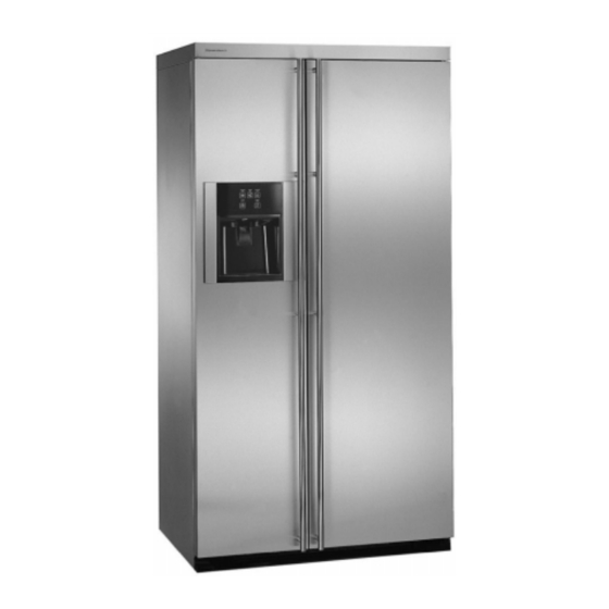
- Page 1 Fridge-Freezer Combination Side-by-Side KE 650-2-2T...
- Page 2 Service Manual: H7-420-64-01-A Responsible: D. Rutz KÜPPERSBUSCH HAUSGERÄTE AG Tel.: (0209) 401-733 Kundendienst Fax: (0209) 401-743 Postfach 100 132 Date: 21.08.2000 45801 Gelsenkirchen...
-
Page 3: Table Of Contents
Service Manual KE 650-2-2T Contents Introduction ........................4 Components ........................6 Auto Damper Control Models ................6 Defrost Timer ......................9 No-Frost-System ....................12 Defrost Heater Replacement ................13 Defrost Thermostat Replacement ..............13 Condenser Fan Motor ..................14 Freezer Fan Motor ....................15 Cabinet and Related Components ................ -
Page 4: Introduction
Note: The KE 650-2-2T covered in this Service Manual uses R134a refrigerant. Each part of this manual is divided into sections relating to a general group of components and each section is subdivided into various parts describing a particular component or service procedure. - Page 5 Service Manual KE 650-2-2T General The American style Fridge-Freezer Combination “Side-by-Side“ is the centrepiece of any kitchen. The high quality of workmanship and finish, including stainless steel front, side and top panels, guarantee many years of proud ownership. The appliance is fitted with state of the art technology, such as:...
-
Page 6: Components
Service Manual KE 650-2-2T Components Auto Damper Control Models The Auto Damper model refrigerator has two controls and both have capillary sensing. The Auto Damper controls the fresh food temperature and the Freezer Temperature Control guides the freezer temperature. The fresh food compartment temperature is maintained by a damper assembly located at the back of the temperature control housing. - Page 7 Service Manual KE 650-2-2T 2.1.2 Exchanging the temperature regulator Disconnect the appliance from the mains supply. Open the fresh food door and remove any items on the top shelf. Remove the light cover. To do this, pull the rear corners down and slide the cover forwards.
- Page 8 Service Manual KE 650-2-2T 2.1.3 Auto Damper Control Replacement Complete steps 1 through 10, checking auto damper. Reinstall new auto damper. Reinstall control housing in reverse order of removal. 2.1.4 Auto Damper Control - Exploded View For internal use only...
-
Page 9: Defrost Timer
Service Manual KE 650-2-2T Defrost Timer The freezer evaporator defrosting system is actuated by an electric timer. The timer is mounted in the control housing located in the fresh food compartment. The timer control shaft is designed for screwdriver advancement. When manually setting the timer to initiate defrosting, turn the control shaft clockwise until you establish the approximate location of the defrost cycle. - Page 10 Service Manual KE 650-2-2T 1st Click – The timer turns off the compressor and freezer fan circuit for approximately 23 minutes, and it energises the defrost heater. Once the temperature of the defrost termination thermostat reaches the cut-out point, the termination thermostat will open the circuit to the radiant heater. However, the compressor circuit remains open for the duration of the defrost interval.
- Page 11 Service Manual KE 650-2-2T 2.2.1 Checking the Defrost Timer Disconnect all wires from the timer and attach ohmmeter probes to the terminals specified in the accompanying chart. If no continuity is indicated, the timer is defective. Turn Timer Knob Check between...
-
Page 12: Frost-System
Service Manual KE 650-2-2T No-Frost-System These models use a metal sheath heater to remove accumulated frost from the freezer evaporator and drain through during a defrost cycle. The defrost timer (models) energises the defrost heater every 8 hours of accumulated compressor run time. When the temperature in the thermostat area reaches approximately +6.1°C, the thermostat contacts open the circuit to the defrost heater. -
Page 13: Defrost Heater Replacement
Service Manual KE 650-2-2T Follow step 2 and 3 of testing the heater and thermostat when the evaporator temperature is -9.4°C, or higher. If the meter reads approximately 240K ohms, the defrost thermostat is defective. To use an ohmmeter, set the meter to R x 1K scale. If the reading is approximately 20 to 40 ohms, the defrost heater and thermostat are operative. -
Page 14: Condenser Fan Motor
Service Manual KE 650-2-2T Condenser Fan Motor The condenser fan motor is connected in parallel with the compressor. If the compressor runs but the motor doesn’t, the motor is either defective or disconnected. If neither operates, check the cold control, defrost timer, and the cabinet wiring. -
Page 15: Freezer Fan Motor
Service Manual KE 650-2-2T Freezer Fan Motor The freezer fan circulates the cooled air throughout the fresh food and freezer compartment. The fan blade is made of polyethylene and is pushed onto the shaft. It is important, when replacing the fan blade, that the hub of the fan blade faces out towards the back of the evaporator fan cover. - Page 16 Service Manual KE 650-2-2T 2.7.2 Freezer Fan Motor Replacement Follow steps 1 through 5 “Freezer Fan Motor Diagnosis”. Remove the screws that secure the motor bracket assembly to the fan shroud. Remove the fan blade by pulling it off the shaft.
-
Page 17: Cabinet And Related Components
Service Manual KE 650-2-2T Cabinet and Related Components Adjustable Cantilever Shelves Type 1 – Two support hook frame design Glass or wire cantilever shelves may be available with your refrigerator. To remove a shelf, tilt front up and lift the rear up a fraction of an inch and pull straight out. To lock the shelf into another position, tilt the shelf with the front up. -
Page 18: Cabinet Doors And Associated Parts
Service Manual KE 650-2-2T Cabinet Doors and Associated Parts 3.3.1 Inner Door Liner Replacement The polystyrene inner door liner and the door seal are mounted to the outer panel by screws placed around the door flange. The inner door liner can be replaced without removing the door from the cabinet. -
Page 19: Cabinet Levelling
Service Manual KE 650-2-2T Cabinet Levelling To enhance its appearance and maintain efficient performance, the refrigerator should be level. The front wheels were adjusted at the factory so the doors were properly aligned and the cabinet level. However, jarring in transit, or standing the refrigerator on uneven floors may cause the doors to shift out of alignment. -
Page 20: Hinge Adjustments
Service Manual KE 650-2-2T Hinge Adjustments Hinge adjustments are necessary when: The seal is not sealed sufficiently along the hinge side of the door. The seal is compressed more than 1.6 mm on the hinge side (causing a poor seal elsewhere around the top.) -
Page 21: Water/Ice Dispenser Freezer Door Removal
Service Manual KE 650-2-2T 3.11 Water/Ice Dispenser Freezer Door Removal Before attempting to remove the door hinge, look at your refrigerator and note the exact number and position of all protective shims on the door hinge. Later, when you replace the hinge, these must be positioned correctly. - Page 22 Service Manual KE 650-2-2T Lift the door enough to allow an assistant to withdraw the tubing through the hinge bolts. Then place the door on a smooth, non-abrasive surface. Hinge bolts Mark the location of the bottom hinge with a pencil. Use an 8mm ratchet spanner to remove the 3 screws from the bottom hinge.
-
Page 23: Fountain Assemblies - Manual Slide Control
Service Manual KE 650-2-2T 3.12 Fountain Assemblies – Manual Slide Control Escutcheon mounting screws Grill 3.12.1 Ice and Water Fountain Bracket Assembly Removal Disconnect the unit from the mains. Pull straight out to remove the grill from the fountain sump. - Page 24 Service Manual KE 650-2-2T Carefully pull the assembly out of the fountain housing. You now have full access to the solenoid, dispenser mechanism, PC delay board, lock switch, light socket, and the light switch. To repair the assembly, disconnect electrical quick disconnect.
- Page 25 Service Manual KE 650-2-2T 3.12.3 Checking and Replacing the Actuator Switch Disconnect the unit from the mains. Perform steps 1 to 6 of To Remove Ice & Water Fountain Bracket Assembly. Check the continuity of the switch. If defective, go to step 4.
-
Page 26: Ice Crusher Bin Shelf Assembly
Service Manual KE 650-2-2T Will not dispense ice or water Press lock button 3 times. If another LED lights, replace LED/Switch PC board. When actuator pad is pressed, does fountain light come on? NOTE: Make sure fountain light bulb is good! (a) Check actuator switch and mechanical connections. - Page 27 Service Manual KE 650-2-2T Crusher housing mounting screws Care should be taken when removing the control rod spring to ensure it does not snap back on your finger. When removing the control bracket, hold the clip; this will prevent it from being thrown off.
-
Page 28: Ice/Crusher Bin Shelf Enclosure Assembly
Service Manual KE 650-2-2T Dispenser Impeller mandiplate Auger Auger nut Snow shield Ice diverter Mandible pin Crusher control Actuated blades Replace the parts as required. The number on the blades should face the back of the auger nut. Blade number 4 should be nearest to the auger nut. - Page 29 Service Manual KE 650-2-2T The auger motor make one revolution approximately every three seconds. To determine the free movement of the auger motor, place the selector switch in either cube or crushed position (slide selector models). On electronic models, push the cube or crushed selector pad. Open the freezer door, push and hold the cabinet interlock switch in the closed position while pushing the dispenser actuator pad.
-
Page 30: Icemaker
Service Manual KE 650-2-2T Icemaker Servicing The design of this icemaker allows all of the components to be tested without removing the icemaker or moving the refrigerator away from the wall to access the water valve. Remove the cover and you will see the test points identified on this module. -
Page 31: Test Procedures
Service Manual KE 650-2-2T Test Procedures Ice-maker plugged into power/Shut-off arm down/Freezer cold: Test points L & N will verify 230 volts to icemaker module. (Make sure your test probes go into the test points 12.5 mm.) Test points T & H will verify if the bimetal thermostat is open or closed. -
Page 32: Accessing The Control Box
Service Manual KE 650-2-2T Module, Motor and Support Assembly: Insert Phillips screwdriver in access ports of module. Loosen both screws. Disconnect shut-off arm. Pull mould from support assembly. To remove module only, remove 3 Phillips screws and pull module out of housing. -
Page 33: Module Components
Service Manual KE 650-2-2T Module Components Shut-off arm linkage Motor Staked leads Earth (slightly longer) than other 3 terminals so that earth makes first breaks last when disconnected or plugged in Cam follower Warning Never rotate the blade or the drive gear! It will ruin the main assembly. -
Page 34: Water Fill Adjustments
Service Manual KE 650-2-2T Water Fill Adjustments Turning the water level adjustment screw will move the contact in its relationship with the contact ring segment. This causes the contact to vary the time that the water valve is energised since the contact ring is tapered at the end of the fill time. -
Page 35: Water Problems
Service Manual KE 650-2-2T Water Problems Water quality can cause icemakers to fail or produce unacceptable cubes. If mineral content or sand is a problem, the screen in the fill valve can restrict. A particle of sand can keep the valve from seating properly. - Page 36 Service Manual KE 650-2-2T Thermostat Clips Using needle nose pliers, grasp one of the thermostat clips and pull out. Press in new thermostat, making sure that pins are properly indexed. Using this procedure, it is not necessary to remove the electrical assembly. If you are replacing the module, transfer the clips to the new mould support.
-
Page 37: Installation
Service Manual KE 650-2-2T Installation Installation procedure Start with arm in ”down” position. Follow steps 1, 2, and 3. Into bushing Step 1 Push arm into centre slot white bushing – bottom out. Notch Flange Fill cup Step 2 Step 3... -
Page 38: Leveling Icemaker
Service Manual KE 650-2-2T Leveling Icemaker This device ensures uniform ice crescents. Mounting Screw Hex ¼” screw 1. Loosen 2. Level I/M by sliding left or right in slot of bracket. 3. Tighten. Make sure the refrigerator is level front to back (adjust legs or rollers). -
Page 39: Other Information
Service Manual KE 650-2-2T Other Information Motor connectors can be damaged if leads are removed. The motor is available only as part of the complete module assembly. One revolution of the blade takes three minutes (plus stall time on ice). -
Page 40: Troubleshooting
Service Manual KE 650-2-2T Troubleshooting Warning DISCONNECT THE UNIT FROM THE MAINS Condition Possible Cause Correction Unit does not run No power to fuse box of house Check and advise customer to No light in refrigerator call an electrician Mains socket... - Page 41 Service Manual KE 650-2-2T Condition Possible Cause Correction Unit does not run. Compressor motor See below: Light in refrigerator works - AC circuit open to Refer to wiring diagrams and compressor check circuit - Defective compressor Replace (overload may or may not...
- Page 42 Service Manual KE 650-2-2T Condition Possible Cause Correction Unit runs continuously. The Air duct from freezer to Remove what is blocking the refrigerator compartment not refrigerator is blocked (normal air duct. See ”Air Flow could enough, but freezer wattage reading) Diagram”...
- Page 43 Service Manual KE 650-2-2T Condition Possible Cause Correction Unit runs excessively or Too much warm food placed in Advise customer continuously. The refrigerator refrigerator at one time and freezer compartments are Air (no leak) in sealed system Replace drier and evacuate...
- Page 44 Service Manual KE 650-2-2T Condition Possible Cause Correction Short running cycle. Air circulation See below Refrigerator and freezer compartment are cooling, but - Ventilation around Check and advise customer are not cold enough condenser is blocked - Condenser fan is defective...
- Page 45 Service Manual KE 650-2-2T Condition Possible Cause Correction Run time normal. Refrigerator Air flow problem Check and remove what is compartment is not cold causing the restriction enough, but freezer See “Air Flow Diagram” compartment is normal or Interior sweating See below: possibly colder than normal.
-
Page 46: Specifications
Service Manual KE 650-2-2T Specifications 21’ Dispenser/Non Dispenser Power Requirement 220 - 240V 50Hz Temp. Control Normal setting Cut / Out (±0.9°C) -23.3°C Operating Amps 2.0A Cut / In (±0.9°C) -6.11°C (max.) Condenser -4.44°C Compressor Tecumseh TP1413YXC Capillary Tube Refrigerant Charge... -
Page 47: Wiring Diagrams
Service Manual KE 650-2-2T Wiring diagrams Schematic Wiring Diagram To remove the lead connector from the condenser fan motor, grasp the connector with your thumb inserted between the connector and the locking lever as shown and pull the connector. For internal use only... - Page 48 Service Manual KE 650-2-2T Wiring diagram For internal use only...
- Page 49 Service Manual KE 650-2-2T Refrigerant Flow For internal use only...
Need help?
Do you have a question about the KE 650-2-2T and is the answer not in the manual?
Questions and answers