
Related Manuals for Alcad 201 Series


Summary of Contents for Alcad 201 Series
- Page 1 T E C H N I C A L M A N U A L Tel. 943.63.96.60 Fax 943.63.92.66 Int. Tel. +34 943.63.96.60 info@alcad.net Polígono Arreche-Ugalde, Nº 1 Apdo. 455 E-20305 IRUN - Spain www.alcad.net...
-
Page 2: Table Of Contents
CONTENTS Page 1. DOOR ENTRY SYSTEM • Description • Components 2. TECHNICAL DATA • Standards • Telephones • Audio units • Power supplies • Entrance panels - Entrance panel modules with audio unit - Entrance panel module with card holder - Blank entrance panel module - Entrance panel modules with single row push buttons - Entrance panel modules with double row push buttons... - Page 3 Page 5. CONNECTION AND SET-UP INSTRUCTIONS • Audio unit - Electronic audio unit GRF-001 - Terminal connections - Audio unit set-up - Mixed audio unit GRF-005 - Terminal connections - Audio unit set-up - Audio unit multi entrance without privacy of conversation GRF-003. Audio unit with privacy of conversation GRF-004 - Terminal connections - Audio unit set-up •...
-
Page 4: Door Entry System
DOOR ENTRY SYSTEM DESCRIPTION The door entry system is a security measure in common to all the telephones in the building, widespread use in dwellings today where it cons- whereas the fifth wire is used to call each indivi- titutes a straightforward means controlling physi- dual dwelling. -
Page 5: Components
COMPONENTS TELEPHONES PUSH BUTTONS Fitted in each dwelling, they ena- The elements in the entrance panel ble the user to answer the call from allowing each of the dwellings to be the entrance panel, talk to the caller contacted. The number of push but- and open the door. -
Page 6: Technical Data
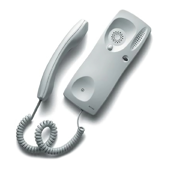
EN50081-1 - Electromagnetic compatibility - Generic emissions standard, EN50082-1 - Electromagnetic compatibility - Immunity. The ALCAD door entry system products are, therefore, marked with the CE Marking. TELEPHONES Ref. 9600001 TEL-001... - Page 7 Ref. 9600002 TUN-001 Description of terminals and UNIVERSAL TELEPHONE voltages: Telephone intended for wall mounting in conven- tional 4+N system. Compatible with door entry systems produced by a broad range of manufactu- TERMINALS REST WORKING rers. Can be used in systems with either an electro- nic call or buzzer.
-
Page 8: Audio Units
AUDIO UNITS Audio units are included in the upper module of the entrance panel (MAN models) and it is not ne- cessary to order a unit separately with these models. Ref. 9610001 GRF-001 Description of terminals and ELECTRONIC AUDIO UNIT 12 V 9 10 11 12 1 2 3 4... - Page 9 Description of Ref. 9610004 GRF-003 terminals and AUDIO UNIT MULTI ENTRANCE WITHOUT voltages: 12 V PRIVACY OF CONVERSATION 9 10 11 12 13 14 15 1 2 3 4 7 16 17 18 Conventional 4+N system. Audio unit for insta- llations in buildings with multiple entrances or resi- dential complexes with one or more general entran- TERMINALS...
-
Page 10: Power Supplies
POWER SUPPLIES Ref. 9620002 ALA-020 Description of terminals and POWER SUPPLY KIT technical characteristics: Power supply for small installations serving up TERMINALS CHARACTERISTICS 230 V 230 V to 12 dwellings. This model of power supply is Mains voltage provided with the kits. 6 component DIN rail format. -
Page 11: Entrance Panels
ENTRANCE PANELS The entrance panel system consists of two modules, each of which is available in va- rious models. These modules make us the upper and lower part of the entrance panel to be installed. Any entrance panel configuration may be obtained by assembling these two modules. -
Page 12: Entrance Panel Modules With Single Row Push Buttons
ENTRANCE PANEL MODULES WITH SINGLE ROW PUSH BUTTONS Lower part of the entrance panel. Module housing the push buttons used to call the various dwellings. Available for 3 to 16 storeys configurations with 1 dwelling per storey. Ref. 9660000 MPS-003 Ref. -
Page 13: Kits
KITS The most convenient solution for installations serving anything from an individual house to a block of up to 12 dwellings. Each kit is supplied with the following elements: • Electronic telephones TEL-001 (Ref. 9600001) - same number of telephones as the number of push buttons on the entrance panel. •... -
Page 14: Accessories
ACCESSORIES ELECTRIC LOCKS 31 mm Ref. 9730000 ABR-001 Opens the entrance door when it receives a 12 V AC STANDARD ELECTRIC LOCK voltage from the audio unit. Remains released while the lock release button on the telephone at the dwelling end remains depressed. -
Page 15: Door Contact
DOOR CONTACT Ref. 9730004 CNP-001 DOOR CONTACT Accessory which, when used in conjunction with an electric lock, allows double doors to be opened. Door contact - Male Door contact - Female PANEL ACCESSORIES It´s necessary to use a flush-mounted box to install the entrace panel in the required place. READY-ASSEMBLED FLUSH-MOUNTED BOXES Available for installations in buildings with 1 to 16 storeys. -
Page 16: Range Of Entrance Panels
RANGE OF ENTRANCE PANELS ENTRANCE PANELS By means of an appropriate combination of entrance panels it is possible to obtain any type of installation configuration: one or more entrance panels, for one or more entrances. The height of the final panel will depend on both the push button panel selected and the upper module selec- ted. - Page 17 The table shows different possible combinations with simple uppermodules, indicating the models used for each panel. Note: To see configurations with double upper modules or several entrance panels refer to the section “Dimensions of entrance panel” on page 22. card holder Blank panels Flush-mounted boxes MTN-000...
- Page 18 Panels with audio unit Panels with c MAN-0 MAN-0 MAN-0 MAN-0 MTN-000 MTN-000 128 mm MPS-011 MPS-012 MPD-011 MPD-012 MPS-011 MPS-012 MAN-0 MAN-0 MAN-0 MAN-0 MTN-000 MTN-000 128 mm MPS-013 MPS-014 MPD-013 MPD-014 MPS-013 MPS-014 MAN-0 MAN-0 MAN-0 MAN-0 MTN-000 MTN-000 128 mm MPS-015...
- Page 19 card holder Blank panels Flush-mounted boxes MTN-000 MTN-000 MLN-000 MLN-000 MLN-000 MLN-000 CMO-012 114 mm MPD-011 MPD-012 MPS-011 MPS-012 MPD-011 MPD-012 MTN-000 MTN-000 MLN-000 MLN-000 MLN-000 MLN-000 CMO-014 114 mm MPD-013 MPD-014 MPS-013 MPS-014 MPD-013 MPD-014 MTN-000 MTN-000 MLN-000 MLN-000 MLN-000 MLN-000 CMO-016...
-
Page 20: Kit Entrance Panels
KIT ENTRANCE PANELS Kits are supplied with all the items needed to install a door entry system. These items include the entran- ce panel. Depending on the kit selected, one of the 9 types of entrance panel listed below will be included. All of these systems include an electronic audio unit for basic installations, GRF-001 (Ref. - Page 21 Ref. 9700002 KAS-01005 5 dwellings kit 8´94” 9´57” 227 mm. 243 mm. 5´04” 4´49” 128 mm. 114 mm. Ref. 9700005 KAD-01003 6 dwellings kit 7´68” 7´05” 195 mm. 179 mm. 5´04” 4´49” 114 mm. 128 mm. Ref. 9700006 KAD-01004 8 dwellings kit 7´68”...
-
Page 22: Dimensions Of Entrance Panels
DIMENSIONS OF ENTRANCE PANELS Configurations with one panel Configurations with two panels Flush mounted boxes 114 mm 243 mm 128 mm 256 mm 114 mm 243 mm 128 mm 256 mm 114 mm 243 mm 128 mm 256 mm 114 mm 243 mm 128 mm 256 mm... - Page 23 Configurations with three panels ush mounted boxes Flush mounted boxes 372 mm 384 mm 372 mm 384 mm 372 mm 384 mm 372 mm 384 mm 372 mm 384 mm 372 mm 384 mm 372 mm 384 mm...
-
Page 24: Assembly
ASSEMBLY FLUSH-MOUNTED BOX REMOVING THE PUNCHED KNOCKOUTS The flush-mounted box has a number of cable entry knockouts. Remove the blanking pieces from those you need. ASSEMBLING SEVERAL BOXES When assembling several boxes together it is necessary to use CEM-001 separators (Ref. -
Page 25: Entrance Panel
ENTRANCE PANEL COMPLETE DISASSEMBLY OF ENTRANCE PANELS The top and bottom stops also have milled shafts. The figure shows the complete disassem- bling of an entrance panel. ASSEMBLING ENTRANCE PANELS Ensure that the separator is correctly fitted to the lower push button panel. Assemble the top and bottom parts of the entrance panel by inserting the milled spindles of the lower panel into the slots in the upper panel. - Page 26 Place the panel rings onto the fixing spindles that have been pulled out. Separate the upper and lower embellishment pieces by loosening the fixing screws. Once connected and before closing the panel, ensure that the unused fixing spindles are inserted fully in their slots.
-
Page 27: Audio Unit
AUDIO UNIT FITTING THE AUDIO UNIT Position the audio unit lighting push-button and push to attach the audio unit to the entrance panel. REMOVING THE AUDIO UNIT Using a screwdriver, lever the audio unit out from its fixings. PUSH BUTTONS FITTING PUSH BUTTONS Push to fix the push buttons on to the entrance panel. -
Page 28: Placing Identifying Labels
PLACING IDENTIFYING LABELS Lever the card holder’s lid up and insert the label identifying each push button. TELEPHONE REMOVING THE BASE COVER Move the cover of the telephone base to the right. Separate the bottom of the cover from the base of the telephone. -
Page 29: Fixing The Base To The Wall
FIXING THE BASE TO THE WALL The base has several fixing points. Using the four most suitable fixing points, fix the telephone base to the wall with the wall plugs and lag screws provided. We recommend that you fix the unit at the four corners. -
Page 30: Power Supply
POWER SUPPLY Remember to protect the power supplies (brea- kers, etc) in order to comply with national safety standards. WALL MOUNTING Fix the power supply to the wall using the screws supplied. FITTING TO A DIN RAIL Fit the power supply to the DIN rail as shown in the diagram. -
Page 31: Connection And Set-Up Instructions
CONNECTION AND SET-UP INSTRUCTIONS AUDIO UNIT ELECTRONIC AUDIO UNIT GRF-001 Ground Power supply voltage Terminal connections Door lock release GRF-001 cod. 96101 Made in Spain Make the connections to the terminals as indi- Telephone common terminal Telephone microphone cated in the didgram. Telephone loudspeaker Common push button terminal (electronic call) 12 V... -
Page 32: Mixed Audio Unit Grf-005
AUDIO UNIT MIXED AUDIO UNIT GRF-005 Ground Power supply voltage Terminal connections Door lock release GRF-005 cod. 96102 Made in Spain Telephone common terminal Make the connections to the terminals as indi- Telephone microphone cated in the diagram. Telephone loudspeaker Common push button terminal (electronic call) 12 V 9 10 11 12... -
Page 33: Terminal Connections
AUDIO UNIT MULTI ENTRANCE WITHOUT Ground Power supply voltage PRIVACY OF CONVERSATION GRF-003 Door lock release GRF-003 Telephone common terminal AUDIO UNIT WITH PRIVACY OF cod. 96104 Telephone microphone GRF-004 Made in Spain cod. 96105 Telephone loudspeaker CONVERSATION GRF-004 Common push button terminal (electronic call) Panel lighting Panel lighting Terminal connections... -
Page 34: Telephone
TELEPHONE ELECTRONIC TELEPHONE TEL-001 Door lock release ELECTRONIC TELEPHONE WITH PRIVACY Common Telephone microphone OF CONVERSATION TES-001 Telephone microphone Terminal connections Electronic call Make the connections to the terminals as indi- cated in the diagram. Call Push button Audio unit UNIVERSAL TELEPHONE TUN-001 Terminal connections Door lock release... -
Page 35: Power Supply
POWER SUPPLY Terminal connections The power supply must be connected on one side to the electrical mains and on the other to the entrance panel audio unit. Make the connections as shown in the diagram. 230 V Mains voltage Ground (to the audio unit) Output voltage (to the audio unit) -
Page 37: Circuit Diagrams
CIRCUIT DIAGRAMS GENERAL POINTS CONCERNING THE INSTALLATION Wire cross-sections When wiring the installation observe the cross-section specifications given below. This will ensure the correct functioning of the door entry system. Up to 150 m Common and call cables 0.25 mm Telephone Power and electric lock cables 0.5 mm... -
Page 38: 4+N System Circuit Diagrams
4+N SYSTEM CIRCUIT DIAGRAMS BASIC INSTALLATION WITH ELECTRONIC CALL 4+N SYSTEM Basic circuit diagram of door entry system installa- tion in buildings with a single entrance. Operation When one of the push buttons on the entrance panel is pressed the electronic call signal generated by the audio unit (7) is sent via the call line to the corresponding telephone (5), where it is heard on the loudspeaker of the handset. - Page 39 BASIC INSTALLATION WITH ELECTRONIC CALL 4+N SYSTEM TABLE OF CROSS SECTIONS Up to 150 meters 0,5 mm 0,8 mm 0,25 mm 0,6 mm Call Call TEL-001 ALA-040 Call Call 230 V 230 V 230 V 9 10 11 12 1 2 3 4 7 MAN-010 MPD-004 ABR-001...
-
Page 40: Basic Installation With Buzzer Call
BASIC INSTALLATION WITH BUZZER CALL 4+N SYSTEM Basic circuit diagram of door entry system installa- tion in buildings with a single entrance. Operation When one of the push buttons on the entrance panel is pressed the call signal generated by the audio unit (8) is sent via the call line to the corres- ponding telephone (6) where it is heard. - Page 41 BASIC INSTALLATION WITH BUZZER CALL 4+N SYSTEM TABLE CROSS SECTIONS Up to 150 meters 0,5 mm 0,8 mm 4 5 6 4 5 6 0,6 mm 0,25 mm Call Call TUN-001 4 5 6 4 5 6 Call Call ALA-040 230 V 230 V 230 V...
-
Page 42: Expansion Of The Installation With Additional Telephones
EXPANSION OF THE INSTALLATION WITH ADDITIONAL TELEPHONES 4+N SYSTEM It is possible to expand a one dwelling system by in the system. If the cross-sections indicated in this adding telephones (maximum 4 telephones per manual are observed, it is possible to install up to 4 system). -
Page 43: Opening The Door From Inside The Building
OPENING THE DOOR FROM INSIDE THE BUILDING 4+N SYSTEM When the entrance door does not have a lock which remains released until the door is ope- handle on the inside push button should be insta- ned could be fitted. lled to activate the lock release. While the electric lock is activated it is possible to open the door. -
Page 44: Microprocessor-Based 4+N System Circuit Diagrams
MICROPROCESSOR-BASED 4+N SYSTEM CIRCUIT DIAGRAMS BASIC INSTALLATION WITH ELECTRONIC CALL MICROPROCESSOR-BASED 4+N SYSTEM tion in buildings with a single entrance. Operation When one of the push buttons on the entrance panel is pressed the electronic call signal generated by the audio unit (7) is sent via the call line to the corresponding telephone (5), where it is heard on the loudspeaker of the handset. - Page 45 BASIC INSTALLATION WITH ELECTRONIC CALL MICROPROCESSOR-BASED 4+N SYSTEM TABLE CROSS SECTIONS Up to 150 meters 0,5 mm 0,8 mm 0,6 mm 0,25 mm Call Call TEL-001 ALA-040 Call Call 230 V 230 V 230 V 10 11 12 13 14 15 1 2 3 4 7 16 17 18 MAN-030...
-
Page 46: Basic Installation With Electronic Call And Privacy Of Conversation
BASIC INSTALLATION WITH ELECTRONIC CALL AND PRIVACY OF CONVERSATION MICROPROCESSOR-BASED 4+N SYSTEM with speech privacy, for use in buildings with a single entrance. Telephones with the privacy of conversation feature remain inactive until they are called from the entrance panel. Until a call is received the dwelling telephone is disabled so that it is not possible to listen to conversations between other telephones and the entrance panel. - Page 47 BASIC INSTALLATION WITH ELECTRONIC CALL AND PRIVACY OF CONVERSATION MICROPROCESSOR-BASED 4+N SYSTEM TABLE CROSS SECTION Up to 150 meters 0,5 mm 0,8 mm 0,6 mm 0,25 mm Call Call TES-001 ALA-040 Call Call 230 V 230 V 230 V 10 11 12 13 14 15 1 2 3 4 7 16 17 18 MAN-040...
-
Page 48: Two Entrance Installation With Electronic Call
This connection sets up the communication between the telephone and the entrance panel. The Alcad multiple entrance systems are based on audio unit starts a fresh 60 second period before the use of microprocessor-controlled audio units removing the control signal (17) and putting both (microprocessor-based 4+N system). - Page 49 TWO ENTRANCE INSTALLATION WITH ELECTRONIC CALL MICROPROCESSOR-BASED 4+N SYSTEM TEL-001 ALA-040 230V 230V 230V 230V ALA-040 MAN-030 MAN-030 MPD-004 MPD-004 ABR-001 ABR-001 MATERIAL REQUIRED MPS -/MPD Push button panel module (depending on characteristics of the installation) 9670004 MAN - 030 Entrance panel module with audio unit multi entrance...
- Page 50 TWO ENTRANCE INSTALLATION WITH ELECTRONIC CALL MICROPROCESSOR-BASED 4+N SYSTEM TABLE CROSS SECTIONS Up to 150 meters 0,5 mm 0,8 mm 0,25 mm 0,6 mm Call Call TEL-001 Call Call 230 V 230 V 230 V 230 V ALA-040 ALA-040 10 11 12 13 14 15 1 2 3 4 7 16 17 18 10 11 12 13 14 15...
-
Page 51: Three Entrance Installation With Electronic Call
Basic circuit diagram of door entry system insta- If the handset is picked up during this time, the llation in buildings with three entrances. Alcad mul- electronics associated to the telephone’s audio tiple entrance systems are based on the use of... - Page 52 THREE ENTRANCE INSTALLATION WITH ELECTRONIC CALL MICROPROCESSOR-BASED 4+N SYSTEM TEL-001 ALA-040 ALA-040 ALA-040 230 V 230 V 230 V 230 V 230 V 230 V MAN-030 MAN-030 MAN-030 MPD-004 MPD-004 MPD-004 ABR-001 ABR-001 ABR-001 MATERIAL REQUIRED MPS-/MPD Push button panel module (depending on characteristics of the installation)
- Page 53 THREE ENTRANCE INSTALLATION WITH ELECTRONIC CALL MICROPROCESSOR-BASED 4+N SYSTEM TABLE CROSS SECTIONS Up to150 meters 0,8 mm 0,5 mm 0,25 mm 0,6 mm Call Call TEL-001 Call Call 230 V 230 V 230 V 230 V 230 V 230 V 230 V 230 V ALA-040...
-
Page 54: Installation With Electronic Call In A Complex With Several Blocks
(7) is sent via the call line to the Alcad multiple entrance systems are based on the corresponding telephone (5), where it is heard on the use of microprocessor-controlled audio units (micro- loudspeaker of the handset. - Page 55 INSTALLATION WITH ELECTRONIC CALL IN A COMPLEX WITH SEVERAL BLOCKS MICROPROCESSOR-BASED 4+N SYSTEM TEL-001 TEL-001 TEL-001 ALA-040 ALA-040 ALA-040 230 V 230 V 230 V 230 V 230 V 230 V MAN-030 MAN-030 MAN-030 MPD-004 MPD-004 MPD-004 BUILDING A BUILDING B BUILDING C ABR-001 ABR-001...
- Page 56 INSTALLATION WITH ELECTRONIC CALL IN A COMPLEX WITH SEVERAL BLOCKS MICROPROCESSOR-BASED 4+N SYSTEM TABLE CROSS SECTIONS Up to150 meters 0,5 mm 0,8 mm 0,6 mm 0,25 mm Call ALA-040 TEL-001 TEL-001 TEL-001 230 V 230 V 10 11 12 13 14 15 1 2 3 4 7 16 17 18 ALA-040...
-
Page 57: Two Entrance Installation With Electronic Call And Privacy Of Conversation
The audio unit also generates a control two entrances. signal (17) that disables the other entrance panel. Alcad multiple entrance systems are based on the The telephone that receives the call is activated by use of microprocessor-controlled audio units (micro- connecting its electronics internally to the common processor-based 4+N system). - Page 58 TWO ENTRANCE INSTALLATION WITH ELECTRONIC CALL AND PRIVACY OF CONVERSATION MICROPROCESSOR-BASED 4+N SYSTEM TES-001 230 V 230 V 230 V 230 V ALA-040 ALA-040 MAN-040 MAN-040 MPD-004 MPD-004 MATERIAL REQUIRED MPS - /MPD Push button panel ABR-001 module(depending ABR-001 on characteristics of the installation) 9670005 MAN - 040...
- Page 59 TWO ENTRANCE INSTALLATION WITH ELECTRONIC CALL AND PRIVACY OF CONVERSATION MICROPROCESSOR-BASED 4+N SYSTEM TABLE CROSS SECTIONS Up to 150 meters 0,8 mm 0,5 mm 0,25 mm 0,6 mm Call Call TES-001 Call Call 230 V 230 V 230 V 230 V ALA-040 ALA-040 10 11 12 13 14 15...
-
Page 60: Three Entrance Installation With Electronic Call And Privacy Of Conversation
The telephone that receives the call is activated by Alcad multiple entrance systems are based on the connecting its electronics internally to the common use of microprocessor-controlled audio units (micro- wire (2) and the door lock release wire (1). While processor-based 4+N system). - Page 61 THREE ENTRANCE INSTALLATION WITH ELECTRONIC CALL AND PRIVACY OF CONVERSATION MICROPROCESSOR-BASED 4+N SYSTEM TES-001 ALA-040 ALA-040 ALA-040 230 V 230 V 230 V 230 V 230 V 230 V MAN-040 MAN-040 MAN-040 MPD-004 MPD-004 MPD-004 ABR-001 ABR-001 ABR-001 MATERIAL REQUIRED MPS-/MPD Push button panel module (depending...
- Page 62 THREE ENTRANCE INSTALLATION WITH ELECTRONIC CALL AND PRIVACY OF CONVERSATION MICROPROCESSOR-BASED 4+N SYSTEM TABLE CROSS SECTIONS Up to 150 meters 0,5 mm 0,8 mm 0,6 mm 0,25 mm Call Call TES-001 Call Call 230 V 230 V 230 V 230 V 230 V 230 V 230 V...
-
Page 63: Installation With Electronic Call And Privacy Of Conversation In A Complex With Several Blocks
(5), where it is heard on the loudspeaker of the handset. At the same time the audio unit’s own loudspeaker Alcad multiple entrance systems are based on the use of generates a sound to confirm to the visitor that the call has microprocessor-controlled audio units (microprocessor-based been made. - Page 64 INSTALLATION WITH ELECTRONIC CALL AND PRIVACY OF CONVERSATION IN A COMPLEX WITH SEVERAL BLOCKS MICROPROCESSOR-BASED 4+N SYSTEM TES-001 TES-001 TES-001 ALA-040 ALA-040 ALA-040 230 V 230 V 230 V 230 V 230 V 230 V MAN-040 MAN-040 MAN-040 MPD-004 MPD-004 MPD-004 ABR-001 ABR-001...
- Page 65 INSTALLATION WITH ELECTRONIC CALL AND PRIVACY OF CONVERSATION IN A COMPLEX WITH SEVERAL BLOCKS MICROPROCESSOR-BASED 4+N SYSTEM TABLE CROSS SECTIONS Up to 150 meters 0,5 mm 0,8 mm 0,25 mm 0,6 mm Call ALA-040 TES-001 TES-001 TES-001 230 V 230 V 10 11 12 13 14 15 1 2 3 4 7 16 17 18...
-
Page 66: Expansion Of The System With Additional Telephones
EXPANSION OF THE SYSTEM WITH ADDITIONAL TELEPHONES MICROPROCESSOR-BASED 4+N SYSTEM Operation It is possible to expand a one dwelling system by The electronic call signal is common to all the adding telephones (maximum 4 telephones per tele-phones. As the call signal is shared between system). -
Page 67: Expansion Of The System With Additional Telephones In Installations With Privacy Of Conversation
EXPANSION OF THE SYSTEM WITH ADDITIONAL TELEPHONES IN INSTALLATIONS WITH PRIVACY OF CONVERSATION MICROPROCESSOR-BASED 4+N SYSTEM Operation It is possible to expand a one dwelling system by The electronic call signal is common to all the tele- adding telephones (maximum 4 telephones per phones. -
Page 68: Opening The Door From Inside The Building
OPENING THE DOOR FROM INSIDE THE BUILDING MICROPROCESSOR-BASED 4+N SYSTEM The push button needs to be fitted near to the When the entrance door does not have a handle, entrance door so that it can be opened while the on the inside a push button should be installed to push button is pressed. -
Page 69: Troubleshooting
TROUBLESHOOTING Check the connections of the various items. To To help you locate possible problems, some of do so, check that the voltages on the various ter- the situations that may arise are described here. minals are those stated in section 2 “Technical data”. - Page 70 A whistling is heard from the entrance The call confirmation cannot be heard at panel. There is feedback. the entrance panel. Reduce the volume of the sound using the volu- Check that the telephones can be heard at the me controls on the audio unit. entrance panel.
-
Page 71: Microprocessor-Based 4+N System
INSTALLATIONS WITH SEVERAL ENTRANCES OR COMPLEXES WITH SEVERAL BLOCKS. MICROPROCESSOR-BASED 4+N SYSTEM In the event of a fault, connect a pair of telephones various entrance panels hooking up the system. If to terminals 1, 2, 3, 4 and to two push-buttons on the no fault is detected, there may be something wrong entrance panel. - Page 72 When calling from one of the entrance The call tone cannot be heard at one of panels the rest of the panels in the the telephones. system are not disabled. Check connections 2 and 5 from the telephone Check connections 17 and 18 between the to the entrance panel.
-
Page 73: Installations With Privacy Of Conversation: Basic Installations With Several Entrances
INSTALLATIONS WITH PRIVACY OF CONVERSATION: BASIC INSTALLATIONS WITH SEVERAL ENTRANCES OR COMPLEXES WITH SEVERAL BLOCKS. MICROPROCESSOR-BASED 4+N SYSTEM In the event of a fault, connect a pair of tele- None of the telephones can be heard phones to terminals 1, 2, 3, 4 and to two push bu- from the entrance panel. - Page 74 A whistling is heard from the entrance When calling from one of the entrance panel. There is feedback. panels the rest of the panels in the system are not disabled (multiple access Reduce the sound level using the volume con- system).
- Page 75 UNIVERSAL TELEPHONE COMPATIBILITY TABLE TUN-001 MODEL In the event of replacements refer to the following table which shows the ALCAD TUN-001 correspondence between terminals ACET from the universal telephone TUN- AMPER 001 and telephones of different ATEA AUTA TF92 (Electrónica) manufacturers.
Need help?
Do you have a question about the 201 Series and is the answer not in the manual?
Questions and answers