Table of Contents
Advertisement
OWNER'S MANUAL
POWERTIG 300DP
WARNING:
Read carefully and understand all ASSEMBLY
AND OPERATION INSTRUCTIONS before
operating. Failure to follow the safety rules and
other basic safety precautions may result in
serious personal injury.
WARNING:
Read carefully and understand all ASSEMBLY
AND OPERATION INSTRUCTIONS before
operating. Failure to follow the safety rules and
other basic safety precautions may result in
1
serious personal injury.
III
Advertisement
Table of Contents

Related Manuals for HUGONG POWERTIG 300DPIII


Summary of Contents for HUGONG POWERTIG 300DPIII
- Page 1 OWNER’S MANUAL POWERTIG 300DP WARNING: Read carefully and understand all ASSEMBLY AND OPERATION INSTRUCTIONS before operating. Failure to follow the safety rules and other basic safety precautions may result in serious personal injury. WARNING: Read carefully and understand all ASSEMBLY AND OPERATION INSTRUCTIONS before operating.
-
Page 2: General Safety Rules
GENERAL SAFETY RULES WARNING: Read and understand all instructions. Failure to follow all instructions listed below may result in serious injury. CAUTION: Do not allow persons to operate or assemble this POWERTIG 300DP welder I I I until they have read this manual and have developed a thorough understanding of how the POWERTIG 300DP welder works. - Page 3 -Do not drape cables over or around your body. -Wear a full coverage helmet with appropriate shade (see ANSI Z87.1 safety standard) and safety glasses while welding. -Wear proper gloves and protective clothing to prevent your skin from being exposed to hot metals, UV and IR rays.
- Page 4 -Cover all bare skin areas exposed to the arc with protective clothing and shoes. Flame-retardant cloth or leather shirts, coats, pants or coveralls are available for protection. -Use screens or other barriers to protect other people from the arc rays emitted from your welding. -Warn people in your welding area when you are going to strike an arc so they can protect themselves.
- Page 5 High pressure cylinders can explode if damaged, so treat them carefully. -Never expose cylinders to high heat, sparks, open flames, mechanical shocks or arcs. -Do not touch cylinder with TIG gun. -Do not weld on the cylinder -Always secure cylinder upright to a cart or stationary object. -Keep cylinders away from welding or electrical circuits.
-
Page 6: Technical Specification
TECHNICAL SPECIFICATION TERM UNIT POWERTIG 300DP I I I Rated Input Voltage Power Frequency 50/60 Rated Input Capacity 12.8 Rated Input Current 18.5 Output No Load Voltage Rated Working Voltage 32V/MMA; 22V/TIG Welding Current 10~ 300 Current Up Time 0~ 15 Current Drop Time 0~... -
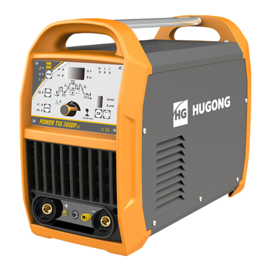
Page 7: Know Your Welder
KNOW YOUR WELDER Description POWERTIG 300DP is a digitization model can be used for MMA、DCTIG and PULSE TIG, the I I I parameters can be preset and showed, welding current can real-time display, this is very easy operation. 1. Front panel 1. - Page 8 The state light of heat protection is on when the machine has over-heated. Let the machine on so that the fan will cool the machine. Wait until the light goes off, and you can continue welding. The state light for wrong voltage turns on if the mains voltage is too high or too low. Check the mains voltage.
- Page 9 1. 2T Operation >1. Press down button of torch, valve starts work, enter pre-flow stage. >2. Setting time of pre-flow is end, machine output the setting welding current. >3. Release button of torch, machine stops work, but valve keeps work, machine enter post flow stage. >4.
- Page 10 1.6.4. Parameters save and load (only available under TIG mode) 1. Parameters saving: > To active the functions of Storage and adjustment, you should press the S/C button last for 2 or 3 seconds, and then the numerical digital of channel become to twinkling. >...
-
Page 11: Installation
INSTALLATION 1.POWER REQUIREMENT - AC 3 phase 400V, 50/60 HZ with a 30 amp circuit breaker is required. DO NOT OPERATE THIS UNIT if the ACTUAL power source voltage is less than 340 volts AC or greater than 460 volts AC. •... -
Page 12: Operation
5. Input connection method Input power Water Input Gas cylinder EXPOSURE TO A WELDING ARC IS EXTREMELY HARMFUL TO THE EYES AND SKIN! Prolonged exposure to the welding arc can cause blindness and burns. Never strike an arc or begin welding until you are adequately protected. Wear flame-proof welding gloves, a heavy long sleeved shirt, trousers without cuffs, high topped shoes, and an ANSI approved welding helmet. -
Page 13: Ground Clamp Connection
Based on different welding position, there are different welding joint, see following images for more information. 1.2. GROUND CLAMP CONNECTION Clear any dirt, rust, scale, oil or paint on the ground clamp. Make certain you have a good solid ground connection. -
Page 14: Welding Techniques
1.4. SELECTING THE PROPER ELECTRODE There is no golden rule that determine the exact rod or heat setting required for every situation. The type and thickness of metal and the position of the work piece determine the electrode type and the amount of heat needed in the welding process. - Page 15 1.6.1. Holding the electrode The best way to grip the electrode holder is the way that feels most comfortable to you. Position the Electrode to the work piece when striking the initial arc it may be necessary to hold the electrode perpendicular to the work piece.
- Page 16 Stringer Bead Weave Bead The weave bead Used when you want to deposit metal over a wider space than would be possible with a stringer bead. It is made by weaving from side to side while moving with the electrode. It is best to hesitate momentarily at each side before weaving back the other way.
- Page 17 1.6.6. Finish the bead As the coating on the outside of the electrode burns off, it forms an envelope of protective gases around the weld. This prevents air from reaching the molten metal and creating an undesirable chemical reaction. The burning coating, however, forms slag. The slag formation appears as an accumulation of dirty metal scale on the finished weld.
- Page 18 Welding regulations parameter table (only for reference) Tungsten Electrode Types TIG Welding is generally regarded as a specialized process that requires operator competency. While many of the principles outlined in the previous Arc Welding section are applicable a comprehensive outline of the TIG Welding process is outside the scope of this Operating Manual.
-
Page 19: Troubleshooting
TROUBLESHOOTING Serial Fault Analysis of fault Method of overcome fault Fan is broken change fan fan don’t connecting cable find where is cable break up rotate drop up (or break and connect it off) switch of torch is change switch of torch broken no arc main control... - Page 20 not work main control change main control board board was broken connecting cable find where is cable break up drop up ( or break and connect it off) Ammeter was change Ammeter broken Ammeter connecting cable find where is cable break up drop up ( or break and connect it display...
-
Page 21: Diagram & Parts List
DIAGRAM & PARTS LIST ERP CODE Name Model Units quantity 20020170016 Handle PMH200.42.12AE12-1/V1.0 11010011527 Cover INVERDELTA 300W ii 20070120109 HF filter capacitor MLC-LS 40uF±5%/800V.DC/60A 20070050002 Fixed plate for driving PCB HG2ZX7400K.2.3-2 11050110250 Power amplify PCB HG2ZX7400K2.3.1 20050050567 Protection plate for IGBT HG2ZX7400K.2.3-3 20050170019 Tension disc... - Page 22 11010021176 Right side panel PMU200.23.12PE12.7 20070430156 Heat sink HG2ZX7400K.7.4-1 12010100117 Rectifier PCB ZX7-400K 11020014513 Up baffle POWERTIG 300DPIII 11010040169 Bottom plate POWERTIG 300KPIII 20020020025 Water pipe connector 8HG.177.018 V3.0 20030302258 Torch switch PTP300.20.14A33.1.2 V3.0 20070660003 Argon connector POWERTIG 300KPIII...
- Page 23 The Circuit Chart...
Need help?
Do you have a question about the POWERTIG 300DPIII and is the answer not in the manual?
Questions and answers