Advertisement
Table of Contents
- 1 General Safety Rules
- 2 Important Safety Considerations
- 3 Product Description
- 4 Safety Operation
- 5 Technical Specifications
- 6 Working Environment
- 7 Installation and Commissioning
- 8 Connection to Power Supply
- 9 Operation
- 10 Front and Back Panel
- 11 Maintenance and Service
- 12 Troubleshooting
- 13 List of Spare Parts
- 14 Schematic Circuit Diagram
- 15 Transport and Storage
- Download this manual
Advertisement
Table of Contents

Subscribe to Our Youtube Channel
Related Manuals for HUGONG INVERMIG 350III


Summary of Contents for HUGONG INVERMIG 350III
- Page 1 OWNER’S MANUAL INVERMIG SERIES WARNING: Read carefully and understand all ASSEMBLY AND OPERATION INSTRUCTIONS before operating. Failure to follow the safety rules and other basic safety precautions may result in serious personal injury.
- Page 2 CATALOGUE GENERAL SAFETY RULES Product Description Safety Operation Technical Specifications Installation and commissioning Operation Trouble Shooting List of Spare Parts Schematic Circuit Diagram Complete Set Specifications Transport & Storage...
-
Page 3: General Safety Rules
GENERAL SAFETY RULES WARNING: Read and understand all instructions. Failure to follow all instructions listed below may result in serious injury. CAUTION: Do not allow persons to operate or assemble this INVERMIG SERIES until they have read this manual and have developed a thorough understanding of how the INVERMIG SERIES works. - Page 4 1.3 Use of Your Welder Do not operate the welder if the output cable, electrode, torch, wire or wire feed system is wet. Do not immerse them in water. These components and the welder must be completely dry before attempting to use them.
- Page 5 -The fumes emitted from some metals when heated are extremely toxic. Refer to the material safety data sheet for the manufacturer’s instructions. -Do not weld near materials that will emit toxic fumes when heated. Vapors from cleaners, sprays and degreasers can be highly toxic when heated. UV and IR Arc Rays The welding arc produces ultraviolet (UV) and infrared (IR) rays that can cause injury to your eyes and skin.
- Page 6 Electromagnetic Field -Electromagnetic fields can interfere with various electrical and electronic devices such as pacemakers. -Consult your doctor before using any electric arc welder or cutting device -Keep people with pacemakers away from your welding area when welding. -Do not wrap cable around your body while welding. -Wrap MIG gun and ground cable together whenever possible.
-
Page 7: Product Description
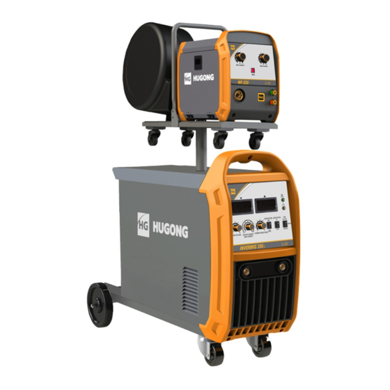
Product Description INVERMIG series——INVERMIG ( MMA/MIG/MAG ) series IGBT inverter welding-type semi-automatic welding machine is an inverter DC semi-automatic welding machine, which is widely used in automation, metal furniture manufacturing, shipyard, pressure container manufacturing and steel construction industries. This machine employs IGBT module and fast recovery diode as main parts for power transition and transfer. - Page 8 2.2 Attention * The knob on the panel can’t change or adjust with a rush otherwise it will be damaged. * Check the connection to see if the welder input and output cables are well connected, whether the earth (ground) connection is reliable, etc. * Never allow anybody else other than the operator himself to dislocate or modulate the welding machine.
-
Page 9: Technical Specifications
Technical Specifications 3.1 Working Environment * The surrounding temperature range: when welding: water cooling: -10 ~﹢40℃, During transport or in storage:﹣25 ~﹢55℃. * Relative humidity: when at 40℃: ≤50%, when at 20℃: ≤90%. * The dust, acid and erodible materials in the air can not exceed the amount required by the mode (apart from the emissions from the welder). - Page 10 3.5 Welder Type Coding * Combination of the Chinese mandarin spelling and the Arabic numerals. * Implication of Coding: INVERMIG XXX Economic models Rated welding current(A) INVERTER CO2/MAG welding machine 3.6 Technical data INVERMIG 350 INVERMIG 400 INVERMIG 500 ITEM IIII IIII IIII...
- Page 11 3.9 Arc ending Usually there is a crater at the end of welding. It is due to the arc pressure and condensing shrinkage of melted metal. The higher arc, the more crater. the arc ending function will fill up the crater by arc ending current (less than 40%-70% of welding current) and improve the welding quality.
-
Page 12: Installation And Commissioning
...A: Current Unit (Ampere) ...KVA: Power Unit (KVA) ...%: Duty Cycle Unit ...A/...V~...A/...V: Output Range. Rated minimum and maximum welding current and related load voltage. IP21S: Case Protection Class. ‘IP’ is the code of International Protection. ‘2’ mean preventing user’s finger from the dangerous parts;... - Page 13 4.3 Connection to wire feeder * Connect quick connector (male) of connecting cable to the “+” socket on the back panel of welding machine, and twist the quick connector (male) clockwise to ensure the tight connection. Connect other end of connecting cable with wire feeder, and ensure the tight connection. * Connect the joint of 6-core control cable with welding machine and wire feeder respectively.
-
Page 14: Operation
Operation 5.1.Front and back panel 1. Socket (+): Connecting Welding cable to wire feeder. 2. Control socket for wire feeder 3. Control Panel GUI: Status display, function selection and welding parameters, when welding the actual current and voltage display, and so on 4. - Page 15 5.3 Control Panel GUI 1. Current indication 2. Voltage indication 3. Main power indicator (Green) 4. Protection indicator (Red) 5. Working indicator (red) 6. MIG mode selection button 7. MIG parameter adjustment selection button: is manual. is unified, user can adjust welding currents and the voltage will matching automatic in unified mode, and the arc length is from -30 to 30, and 0 is recommend.
-
Page 16: Maintenance And Service
5.4 Arc ending Set arc ending mode switch to “ON”. The operator shall adjust and set welding current, arc ending current, welding voltage, and arc ending voltage. (Usually the arc ending current is less then welding current, the valve shall be set according to the crater.). -
Page 17: Troubleshooting
needs cleaning once or even twice every quarter if the dust accumulation problem is serious. * Regularly check the input & output cables of welder to guarantee them right and firmly connected and avoid them being exposed. Check should be taken once every month when fixed using and every check taken when removing. - Page 18 change shallow base plate groove is too deep plate groove the former molten slag of welding bead is not cleaned remove molten slag Slag increase current small current, too much weld slowly deposition, to much Inclusion and reduce the swing swing during welding during welding welding current and voltage doesn’t match...
- Page 19 Electropneumatic value Repair or change the Electropneumatic broken value Control board is broken Change or repair the control board Cable connection is not good Connect the cable Function is ok, but Motor is broken Repair or change the motor no wire feeding Control board is broken Change or repair the control board connection is not good or...
-
Page 20: List Of Spare Parts
List of Spare Parts code(EBS) English names specifications unit dosage 11050050447 wire feeder assembly INVERMIG 500E 20200010604 feeder fixed axle ¢26.8*210/INVERMIG 500WII 11010011794 outside shell INVERMIG 350W 20070250045 Power transformer PM500.10.24D33.3.1.1 NF313B30/05 20070440007 Three phase filter 440/250VAC/30A 11020013994 filter plate WELDMATIC 500I 11010050298 Mounting plate INVERMIG 350WII... - Page 21 20070800126 breaker DZ47-60A-D 63A/415V/3P 11020011828 switch holder 8HG.125.044 11010032553 Rear panel INVERMIG 350W 20070890148 fan 200FZY8-S 80W/0.22A 11010021206 right panel INVERMIG 350W 20050070071 rubber wheel 13B-200×50 11020013348 About wind deflector NB500E/PM500.10.24D33-2 11020015863 Fast recovery radiator mounting bracket INVERMIG 350W 11010060796 On the bottom panel NB500E/PM500.10.24D33.8-1 20050070036 universal wheel WP12B-75×30...
-
Page 22: Schematic Circuit Diagram
Schematic Circuit Diagram The circuit diagram is for reference. -
Page 23: Transport And Storage
Complete Set Specifications 1)INVERMIG machine power source 1 pc 2)wire feeder 1pc Accessories list INVERMIG -350 /400 INVERMIG-500 Description Specification Quantity Specification Quantity Torch 350A 500A Roller 0.8-1.0 1.0-1.2 Contact tips Φ1.0、Φ1.2 Each type 1pc Φ1.2、Φ1.6 Each type 1pc Gas regulator 36VAC 36VAC fuse...
Need help?
Do you have a question about the INVERMIG 350III and is the answer not in the manual?
Questions and answers