Table of Contents
Advertisement
Advertisement
Table of Contents

Related Manuals for AIC J4024-02


Summary of Contents for AIC J4024-02
- Page 1 J4024-02 12Gb/s SAS JBOD Series User's Manual UM_J4024-02_v8.1_121619...
-
Page 2: Table Of Contents
3.5.1 How to enable/disable T10 zoning ..............26 3.5.2 How to configure T10 zoning ................27 3.5.3 How to get all revisions in AIC SAS 12G Expander ........29 3.5.4 How to configure temperature sensor ............30 3.5.5 How to configure enclosure address .............. 31 3.5.6 How to configure standby timer for all disk drives ........ - Page 3 3.5.7 How to configure wide port checker ............... 33 3.5.8 How to configure serial number ..............35 3.5.9 How to power off/on all disk drives automatically ........36 3.5.10 How to configure EDFB ................. 37 3.5.11 How to configure power setting ..............38 3�6 SES Inband Features �����������������������������������������������������������������������40 3.6.1 SES pages supported are listed below ............
- Page 4 Copyright © 2017 AIC, Inc. All Rights Reserved. This document contains proprietary information about AIC products and is not to be disclosed or used except in accordance with applicable agreements.
- Page 5 Document Release History Release Date Version Update Content 2017 Manual release to public June Content update 2018 1. New cover December 2019 2. BMC update...
-
Page 6: Preface
Disclaimer AIC shall not be liable for technical or editorial errors or omissions contained herein. The information provided is provided "as is" without warranty of any kind. To the extent permitted by law, neither AIC or its affiliates, subcontractors or suppliers will be liable for incidental, special or consequential damages including downtime cost;... -
Page 7: Safety Instructions
Safety Instructions Before getting started, please read the following important cautions: • All cautions and warnings on the equipment or in the manuals should be noted. • Most electronic components are sensitive to electrical static discharge. Therefore, be sure to ground yourself at all times when installing the internal components. •... - Page 8 • If one of the following situations arise, the equipment should be checked by service personnel: 1. The power cord or plug is damaged. 2. Liquid has penetrated the equipment. 3. The equipment has been exposed to moisture. 4. The equipment does not work well or will not work according to its user manual. 5.
-
Page 9: About This Manual
This document pellucidly presents a brief overview of the product design, device installation, and firmware settings for J4024-02. For the latest version of this user's manual, please refer to the AIC website: https://www.aicipc.com/en/productdetail/253. -
Page 10: Chapter 1� Product Features
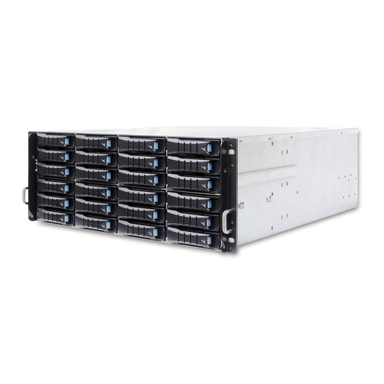
Chapter 1� Product Features J4024-02 User Manual Chapter 1. Product Features J4024-02 is a 4U high density JBOD with 24 hot swappable drive bays and hotswappable fans. For more information about our product, please visit our website https://www.aicipc.com/en/productdetail/253. Before removing the subsystem from the shipping carton, visually inspect the physical condition of the shipping carton. -
Page 11: Specifications
Dual expanders (Optional) 1�3 Feature J4024-02 is a reliable SAS JBOD with 3.5-inch x 24 hotswap drives bays. This product is designed to accommodate single/dual expanders and 3 Mini SAS HD per expander module. Featuring the expander chip, Broadcom SAS3x36R, which is emphasized for... - Page 12 J4024-02 User Manual Chapter 1. Product Features Front Panel NOTE To prevent energy hazard from the DC connector located in the front panel, please use the screw to secure the cover protecting the connector.
- Page 13 J4024-02 User Manual Chapter 1. Product Features Rear Expender Panel 2 Dual Expander (Primary & Secondary)
- Page 14 J4024-02 User Manual Chapter 1. Product Features Rear Panel...
-
Page 15: Chapter 2� Hardware Setup
Chapter 2� Hardware Setup J4024-02 User Manual Chapter 2. Hardware Setup 2�1 Top Cover 2�1�1 Chassis Cover Remove the screws on the top cover. Slide the top cover towards the rear end of the system barebone. Lift the cover upward to remove. -
Page 16: 2�2 Power Supply Unit Module
J4024-02 User Manual Chapter 2. Hardware Setup 2�2 Power Supply Unit Module Pull the handle to remove the module out of the chassis. Push the new power supply unit into the chassis. Ensure that the module is robustly hooked into the cage. -
Page 17: 2�3 Fan Module
J4024-02 User Manual Chapter 2. Hardware Setup 2�3 Fan Module Loosen the thumb screws on the fan module. Pull the fan module out of the chassis. Align the new fan module with the opening in the enclosure. -
Page 18: 2�4 Disk Drive Module
J4024-02 User Manual Chapter 2. Hardware Setup 2�4 Disk Drive Module 2�4�1 Disk Drive Press the release button the tray lever to loosen the lever. Pull the tray lever outward completely. Pull the tray out of the system. -
Page 19: Disk Drive With Interposer
J4024-02 User Manual Chapter 2. Hardware Setup 2�4�2 Disk Drive with Interposer Adjust and place the 3.5” HDD on the HDD tray. Secure it with screws on the bottom. Mounting location : HDD with the interposer board attached. -
Page 20: Drive Slot Map
J4024-02 User Manual Chapter 2. Hardware Setup 2�4�3 Drive Slot Map The drive slot map follows. -
Page 21: 2�5 Hdd Backplane Module
J4024-02 User Manual Chapter 2. Hardware Setup 2�5 HDD Backplane Module Detach the cables and hard disk drives from the backplane module. Release the module by shifting the hook. Dislodge the screws on the module. Lift the module upward to remove. -
Page 22: 2�6 Expander Module
J4024-02 User Manual Chapter 2. Hardware Setup 2�6 Expander Module Loosen the thumb screw to release the expander tray lever. Pull the expander module out of enclosure. Align the new expander module with the expander slot and insert it into the chassis. -
Page 23: 2�7 Bmc Module
J4024-02 User Manual Chapter 2. Hardware Setup 2�7 BMC Module Remove the expander module from the chassis. Please refer to section 2.4. Place the BMC module on the Expander Module. Make sure to match the screw holes. Secure the screws. -
Page 24: 2�8 Slide Rail Installation
J4024-02 User Manual Chapter 2. Hardware Setup 2�8 Slide Rail Installation To install the slide rail, please refer to the manual in the slide rail kit. NOTE The product installation position is less than 1 meter in height from the supporting... - Page 25 J4024-02 User Manual Chapter 2. Hardware Setup Install the rear of JBOD onto the rack by following procedure 1a~1b. 1a. Secure the adjuster plate on the rack using the screws. 1b. Insert the slide rail into the adjuster plate and make sure the slide rail is fully...
- Page 26 J4024-02 User Manual Chapter 2. Hardware Setup Installing the front of JBOD onto the rack by following the procedure 2a~2b. 2a. Secure the JBOD on the rack using the screws. 2b. Complete installing the JBOD.
-
Page 27: Chapter 3. Sub-System Configuration Setup
Each AIC 12G Expander Controller NOTE To have multiple host access support (the host number can be up to the number of wide ports on each AIC 12G expander controller), only the followng drives are supported for shared access: 1. SAS drive... -
Page 28: 3�2 Connect Host To Jbod Via Rs232
J4024-02 User Manual Chapter 3. Sub-system Configuration Setup 3�2 Connect Host to JBOD via RS232 Use a RS-232 DB9 cable to connect the console port of JBOD with host's PC COM port (see figures below for DB9 RS-232 cable and SAS expander COM port). -
Page 29: 3�3 Utility Setup On Host
J4024-02 User Manual Chapter 3. Sub-system Configuration Setup 3�3 Utility Setup on Host Step 1 Set up host RS232 connection Set up RS232 connection application into your host as shown in the example process below. For example: OS: Microsoft Windows Server 2008 RS232 connection application: Hyperterminal Step 2 Install HyperTrm.exe... - Page 30 J4024-02 User Manual Chapter 3. Sub-system Configuration Setup Step 3 Enter a new name for the icon in the field below and click OK. Step 4 Connect by using selecting an option in the drop down menu circled in red...
- Page 31 J4024-02 User Manual Chapter 3. Sub-system Configuration Setup Step 5 Under “Bits per second,” select 38400. Under “Flow control,” select "None." Click OK when you have finished your selections. Step 6 After step 5, you will enter hyper terminal screen. Please press the "Enter" key...
-
Page 32: Updating Firmware And Mfg Through Console Port
J4024-02 User Manual Chapter 3. Sub-system Configuration Setup 3.4 Updating Firmware and MFG through Console Port Step 1 Please input “fdl 0 0” in command line to update the firmware. Step 2 Select the tool bar ''Transfer'' ''Send File'' within 10 seconds. - Page 33 J4024-02 User Manual Chapter 3. Sub-system Configuration Setup Step 3 Select the Firmware file and set the Protocol type as “Xmodem.” Then press the “Send” button. Step 4 After completing the FW update, “ Buffer Download Complete” will show on the...
- Page 34 J4024-02 User Manual Chapter 3. Sub-system Configuration Setup Step 5 Input “fdl 83 0” in commond line to update the MFG. Step 6 Go to the Transfer menu and then select “Send file” within 10 seconds. Step 7 Select the MFG file and set the Protocol type as “Xmodem.” Then press the “Send”...
-
Page 35: How To Enable/Disable T10 Zoning
J4024-02 User Manual Chapter 3. Sub-system Configuration Setup 3.5.1 How to enable/disable T10 zoning The default T10 zoning configuration is off. (A) Check the current zoning state cmd> phyzone state Zoning is OFF (B) Enable zoning cmd> phyzone on (C) Disable zoning... -
Page 36: How To Configure T10 Zoning
J4024-02 User Manual Chapter 3. Sub-system Configuration Setup 3.5.2 How to configure T10 zoning After enabling T10 zoning, five predefined groups are Group1, Group8, Group9, Group10, and Group11. Each PHY should be in one of the five groups, and all PHYs in a wide port should be in the same group. - Page 37 J4024-02 User Manual Chapter 3. Sub-system Configuration Setup...
-
Page 38: How To Get All Revisions In Aic Sas 12G Expander
J4024-02 User Manual Chapter 3. Sub-system Configuration Setup 3.5.3 How to get all revisions in AIC SAS 12G Expander (A) Expander firmware revision cmd> rev (B) Expander configuration revision cmd> showmfg (C) MCU firmware revision and sensor information cmd> sensor... -
Page 39: How To Configure Temperature Sensor
J4024-02 User Manual Chapter 3. Sub-system Configuration Setup 3.5.4 How to configure temperature sensor Four temperature settings in Celsius are T1, T2, warning threshold, and alarm (critical) threshold. The T1, T2 and alarm (critical) threshold are applied to the smart fan funcion. -
Page 40: How To Configure Enclosure Address
J4024-02 User Manual Chapter 3. Sub-system Configuration Setup 3.5.5 How to configure enclosure address (A) Get the current enclosure address cmd> enclosure_addr Enclosure Address: 0x500605B0000272BF (B) Set the enclosure address with 0x500605B0000272BF. The new setting will take effect after reset. -
Page 41: How To Configure Standby Timer For All Disk Drives
J4024-02 User Manual Chapter 3. Sub-system Configuration Setup 3.5.6 How to configure standby timer for all disk drives This feature is applicable for SAS/SATA drives. Standby timer is in units of minutes. Setting standby timer with 0 minute disables this feature. -
Page 42: How To Configure Wide Port Checker
This feature is applicable for SAS drives instead of SATA drives. If there is no connection with any active SAS initiator by checking all wide ports, AIC Expander Controller stops all attached SAS drives to save power consumption of SAS drives. - Page 43 J4024-02 User Manual Chapter 3. Sub-system Configuration Setup...
-
Page 44: How To Configure Serial Number
J4024-02 User Manual Chapter 3. Sub-system Configuration Setup 3.5.8 How to configure serial number (A) Get the current serial number cmd> serial_number E x p a n d e r n u m b e r: 4 2 1 - 1 2 0 2 1 7 0 4 5 1 0 0 1 0 o r E x p a n d e r n u m b e r: 4 2 1 - 12021704510010 Enclosure number: 526-12071100500088 (B) Only set Expander serial number with 421-12021704510010. -
Page 45: How To Power Off/On All Disk Drives Automatically
3�5�9 How to power off/on all disk drives automatically This feature is applicable for SAS/SATA drives. If there is no connection with any active SAS initiator by checking all wide ports, AIC Expander Controller powers off all attached SAS/SATA drives to save power consumption. Otherwise, AIC Expander Controller powers on all attached SAS/SATA drives to provide drive access service to any active SAS initiator. -
Page 46: How To Configure Edfb
J4024-02 User Manual Chapter 3. Sub-system Configuration Setup 3.5.10 How to configure EDFB The default EDFB configuration is off. (A) Check the current configuration cmd> edfb EDFB is OFF (B)Enable the EDFB, the new setting will take effect after reset. -
Page 47: How To Configure Power Setting
J4024-02 User Manual Chapter 3. Sub-system Configuration Setup 3.5.11 How to configure power setting This feature is for restoring on AC power loss. Three supported options are "keep off", "keep on", and "keep last state". The default setting is "keep off". - Page 48 J4024-02 User Manual Chapter 3. Sub-system Configuration Setup...
-
Page 49: 3�6 Ses Inband Features
Chapter 3. Sub-system Configuration Setup 3�6 SES Inband Features To ensure J4024-02 can work properly and provide high performance, durability. J4024- 02 has implemented SCSI Enclosure Services to monitor the status of power supply, system cooling fan and working temperature. It also has the indicators to deliver the status of fail devices such as power supply or cooling fan. -
Page 50: Implementation On Ses
J4024-02 User Manual Chapter 3. Sub-system Configuration Setup 3.6.3 Implementation on SES Pages 3.6.3.1 SES String In Page Get PMBUS information with String In Page. String In Format Byte 0 I2C congestion status (0: no congestion, 1: congestion) Byte 1~2... - Page 51 J4024-02 User Manual Chapter 3. Sub-system Configuration Setup 3.6.3.3 SES Vendor specific page: Chassis Number ( page code 82h) Out / In The length N of chassis number can be 0 to 30 bytes. If no chassis number is entered (N=0), then chassis number is cleared.
- Page 52 J4024-02 User Manual Chapter 3. Sub-system Configuration Setup 3.6.3.5 SES Vendor specific page: Control Option ( page code 84h) Out / In We can change two settings in this page: (1) Bezel LED State: Set Bezel LED state for testing.
-
Page 53: Implementation On Ses Elements
J4024-02 User Manual Chapter 3. Sub-system Configuration Setup 3�6�4 Implementation on SES Elements Only the fields highlighted in green are supported. 3.6.4.1. Power Supply Element (A) Power Supply Control Element BYTE/BIT COMMON CONTROL SELECT PRDFAIL DISABLE RST SWAP Reserved RQST... - Page 54 J4024-02 User Manual Chapter 3. Sub-system Configuration Setup 3.6.4.2 Cooling Element (A) Cooling Control Element BYTE/BIT COMMON CONTROL SELECT PRDFAIL DISABLE RST SWAP Reserved RQST Reserved IDENT Reserved RQST FAIL RQST ON Reserved REQUESTED SPEED CODE Field Value RQST IDENT Please refer to section “SES Element Control Functions”...
- Page 55 J4024-02 User Manual Chapter 3. Sub-system Configuration Setup 3.6.4.3 Temperature Sensor Element (A) Temperature Sensor Control Element BYTE/BIT COMMON CONTROL SELECT PRDFAIL DISABLE RST SWAP Reserved RQST RQST FAIL Reserved IDENT Reserved Reserved (B) Temperature Sensor Status Element BYTE/BIT COMMON STATUS...
- Page 56 J4024-02 User Manual Chapter 3. Sub-system Configuration Setup 3.6.4.4 Enclosure Element (A) Enclosure Control Element BYTE/BIT COMMON CONTROL SELECT PRDFAIL DISABLE RST SWAP Reserved RQST Reserved IDENT POWER CYCLE POWER CYCLE DELAY REQUEST REQUEST REQUEST POWER OFF DURATION FAILURE WARNING...
- Page 57 J4024-02 User Manual Chapter 3. Sub-system Configuration Setup 3.6.4.5 Voltage Element (A) Voltage Control Element BYTE/BIT COMMON CONTROL SELECT PRDFAIL DISABLE RST SWAP Reserved RQST RQST FAIL Reserved IDENT Reserved Reserved (B) Voltage Status Element BYTE/BIT COMMON STATUS Reserved PRDFAIL...
- Page 58 J4024-02 User Manual Chapter 3. Sub-system Configuration Setup 3.6.4.6 Array Device Element (A) Array Device Control Element BYTE/BIT COMMON CONTROL SELECT PRDFAIL DISABLE RST SWAP Reserved RQST RQST RQST RQST IN RQST RQST HOT RQST R/R RQST OK RSVD CONS...
- Page 59 J4024-02 User Manual Chapter 3. Sub-system Configuration Setup (B) Array Device Status Element BYTE/BIT COMMON STATUS Reserved PRDFAIL DISABLE SWAP ELEMENT STATUS CODE RSVD IN CRIT IN FAILED REBUILD/ HOT SPARE CONS CHK R/R ABORT DEVICE ARRAY ARRAY REMAP CLIENT...
-
Page 60: Ses Element Control Functions
J4024-02 User Manual Chapter 3. Sub-system Configuration Setup 3�6�5 SES Element Control Functions 3.6.5.1 LED indicators (blue and red) associated with an attached disk drive Array Device Slot control element BYTE/BIT COMMON CONTROL SELECT PRDFAIL DISABLE RST SWAP Reserved RQST... - Page 61 We use the software package "sg3_utils" on Linux for example, and have a SAS HBA and a cable to connect your host with the expander. (A) Show the device for AIC Expander Controller (canister) $ sg_map -i /dev/sg2 AIC 12G 4U24SAS3swap 0c0b (B) Get the current state of a slot power.
- Page 62 Linux for example, and have a SAS HBA and a cable to connect your host with the expander. (A) Show the device for AIC Expander Controller (canister) on a disk backplane $ sg_map -i /dev/sg2 AIC 12G 4U24SAS3swap 0c0b...
- Page 63 “PowerSupply02” to power off the entire enclosure. We use the software package "sg3_ utils" on Linux for example, and have a SAS HBA and a cable to connect your host with the expander. (A) Show the device for AIC Expander Controller (canister) $ sg_map -i /dev/sg2 AIC 12G 4U24SAS3swap 0c0b...
- Page 64 Clear the bit to disable the identity. We use the software package "sg3_ utils" on Linux for example, and have a SAS HBA and a cable to connect your host with the expander. (A) Show the device for AIC Expander Controller (canister) $ sg_map -i /dev/sg2 AIC 12G 4U24SAS3swap 0c0b...
- Page 65 We use the software package "sg3_utils" on Linux for example, and have a SAS HBA and a cable to connect your host with the expander. (A) Show the device for AIC Expander Controller (canister) $ sg_map -i /dev/sg2 AIC 12G 4U24SAS3swap 0c0b...
- Page 66 We use the software package "sg3_utils" on Linux for example, and have a SAS HBA and a cable to connect your host with the expander. (A) Show the device for AIC Expander Controller (canister) $ sg_map -i /dev/sg2 AIC 12G 4U24SAS3swap 0c0b (B) Set "RQST IDENT"...
- Page 67 J4024-02 User Manual Chapter 3. Sub-system Configuration Setup REQUESTED SPEED CODE 100% Leave at current speed...
-
Page 68: Chapter 4. Bmc Configuration Settings
Chapter 4. BMC Configuration Settings J4024-02 User Manual Chapter 4. BMC Configuration Settings 4.1 Login Open a web browser and enter the default IP http://192�168�11�11. When the login window appears, set the user name to Admin and leave the password box empty. Click Log In to continue. -
Page 69: 4�2 Sensor's Location For Fan And Temperature
J4024-02 User Manual Chapter 4. BMC Configuration Settings 4�2 Sensor's Location for Fan and Temperature EXP: expander chip Fan1 Fan0 FRONT... -
Page 70: 4�3 Utility Setup On Host
J4024-02 User Manual Chapter 4. BMC Configuration Settings 4�3 Utility Setup on Host Please refer to Section 3.2 4�4 Connect Host to BMC by RS232 1. Type the “[” and it will show the IPMI serial interface. Type in the command for logging in the interface. - Page 71 J4024-02 User Manual Chapter 4. BMC Configuration Settings 2. Find LAN information Find LAN static IP /DHCP [30 00 02 01 04 00 00 ] Find LAN IP [30 00 02 01 03 00 00 ] Find submask [30 00 02 01 06 00 00 ]...
- Page 72 J4024-02 User Manual Chapter 4. BMC Configuration Settings 3. Set LAN information Set LAN information Set LAN static IP /DHCP [30 00 01 01 04 01/02 ] Set LAN IP [30 00 01 01 03 C0 A8 00 0A ]...
-
Page 73: Bmc Led Signal
J4024-02 User Manual Chapter 4. BMC Configuration Settings 4.5 BMC LED Signal There are have two LEDs under the BMC console port. Blue LED Light- Identify LED. Red LED Light- When the light keep blinking, means BMC got error. -
Page 74: 4�6 Web
J4024-02 User Manual Chapter 4. BMC Configuration Settings 4�6 Web UI 4�6�1 Dashboard Device Information Displays the Firmware Revision and Firmware Build Time (Date and Time). Network Information Shows network settings for the device. Click on the link Edit to view the Network Settings Page. -
Page 75: Fru Information
J4024-02 User Manual Chapter 4. BMC Configuration Settings 4�6�2 FRU information This page displays the BMC FRU file information. On selecting a particular FRU Device ID its corresponding FRU information will be displayed. Basic Information It displays the FRU device ID and device name for the selected FRU device ID. -
Page 76: Hard Disk Status
J4024-02 User Manual Chapter 4. BMC Configuration Settings 4�6�3 Hard Disk Status This page displays all the HDD power on/off status, using the "Power On" and "Power Off" button to control HDD status. ACTIONS Power On Select a HDD to turn it power on. -
Page 77: Storage Health
J4024-02 User Manual Chapter 4. BMC Configuration Settings 4.6.4 Storage Health 4.6.4.1 Sensor Readings A list of sensor readings will be displayed here. Click on a record to show more information about that particular sensor, including thresholds and a graphical representation of all associated events. - Page 78 J4024-02 User Manual Chapter 4. BMC Configuration Settings 4.6.4.2 Event Log This page displays the list of events incurred by different sensors on this device. Double click on a record to see the details of that entry. You can also sort the list of entries by clicking on any of the column headers.
-
Page 79: Configuration
J4024-02 User Manual Chapter 4. BMC Configuration Settings 4.6.5 Configuration 4.6.5.1 DNS This page is used to configure the Host name and Domain Name Server configuration of the device. Host configuration Host Settings Choose either Automatic or Manual settings. Host Name It displays the hostname of the device if Auto is selected. If the Host setting is chosen as Manual, then specify the hostname of the device. - Page 80 J4024-02 User Manual Chapter 4. BMC Configuration Settings Domain Name Server Configuration DNS Server Settings It lists the options for the DNS interface, Manual and available LAN interfaces. IP Priority If the IP Priority is IPv4, it will have 2 IPv4 DNS servers and 1 IPv6 DNS server.
- Page 81 J4024-02 User Manual Chapter 4. BMC Configuration Settings 4.6.5.2 Network This page is used to configure the network settings for available LAN channels. LAN Interface Select the LAN interface to be configured. LAN Settings Check this option to enable LAN support for the selected interface.
- Page 82 J4024-02 User Manual Chapter 4. BMC Configuration Settings Obtain an IP address automatically Enable ‘Use DHCP’ to dynamically configure the IPv4 address using Dynamic Host Configuration Protocol (DHCP). IPv6 Address Specify a static IPv6 address to be configured for the selected interface.
- Page 83 J4024-02 User Manual Chapter 4. BMC Configuration Settings 4.6.5.3 Network Link This page is used to configure the network link option for the available network interfaces. LAN Interface Select the network interface from the list for which the Link speed and duplex mode are to be configured.
- Page 84 J4024-02 User Manual Chapter 4. BMC Configuration Settings 4.6.5.4 NTP This page displays the device’s current Date & Time Settings. It can be used to configure either Date & Time or NTP (Network Time Protocol) server settings for the device.
- Page 85 J4024-02 User Manual Chapter 4. BMC Configuration Settings UTC Offset UTC Offset list contains the UTC offset values for the NTP server, which can be used to display the exact local time. NOTE Use the correct UTC Offset after adjusting for DST. to automatically synchronize.
- Page 86 J4024-02 User Manual Chapter 4. BMC Configuration Settings 4.6.5.5 PEF This page is used to configure the Event Filter, Alert Policy and LAN Destination. To view the page, the user must at least be an Operator. To modify or add a PEF, the user must be an Administrator.
- Page 87 J4024-02 User Manual Chapter 4. BMC Configuration Settings Select a free slot and click ‘Add’ to add a new entry to the device. Alternatively, double click on a free slot. Modify Select a configured slot and click ‘Modify’ to modify that entry. Alternatively, double click on the configured slot.
- Page 88 J4024-02 User Manual Chapter 4. BMC Configuration Settings 4.6.5.6 SMTP This page is used to configure the SMTP settings. LAN Channel Number Select the LAN channel to which the SMTP information needs to be configured. Sender Address Enter the ‘Sender Address’ valid on the SMTP Server.
- Page 89 J4024-02 User Manual Chapter 4. BMC Configuration Settings NOTE SMTP Server Authentication types supported are: • CRAM-MDS • Login • Plain If the SMTP server does not support any of the above authentication types, the user will get an error message stating "authentication type is not supported by SMTP server."...
- Page 90 J4024-02 User Manual Chapter 4. BMC Configuration Settings 4.6.5.7 Schedule This page displays the device's current date & time. It can be used to configure dates within a week or specific a date to power on/off the device. If you want to change the device date & time, please go to the NTP page.
- Page 91 J4024-02 User Manual Chapter 4. BMC Configuration Settings 4.6.5.8 User The displayed table shows any configured Users and available slots. You can modify or add new users from here. A maximum of 10 slots are available, including the default admin and anonymous. It is advised that the anonymous user’s privilege and password should be modified as a security measure.
-
Page 92: Remote Control
J4024-02 User Manual Chapter 4. BMC Configuration Settings 4�6�6 Remote Control 4.6.6.1 Storage power control This page helps you to view or perform any host power cycle operations. Reset Expander Select an expander to do cold reset. Power Off Storage Select this option to immediately power off the storage. - Page 93 J4024-02 User Manual Chapter 4. BMC Configuration Settings 4.6.6.2 JAVA SOL NOTE A compatible JRE must be installed in the system prior to the launch of the JNLP file. Launch the Java SOL, you must have Administrator privileges. Choose an expander that can use smart console in Java SOL.
-
Page 94: 4�7 Firmware Update
J4024-02 User Manual Chapter 4. BMC Configuration Settings 4�7 Firmware Update 4�7�1 Requirement Browsers: FireFox 24.0 or later version Chrome 35.0 or later version I.E. 7.0 or later version Linux: Redhat 6.4 NOTE If you want to update a new version firmware for BMC, please clear the web browser cookies when the update process is complete. - Page 95 J4024-02 User Manual Chapter 4. BMC Configuration Settings 3. This is login main page. 4. Click the “Firmware Update” and it will pop a drop-down menu, click the “Firmware Update.”...
- Page 96 J4024-02 User Manual Chapter 4. BMC Configuration Settings 5. This page will show the update warning. If you really want to update BMC firmware, click the “Enter Update Mode” button. 6. Wait few minutes, it will pop a window. Click the “Select file” to upload firmware file...
- Page 97 J4024-02 User Manual Chapter 4. BMC Configuration Settings 7. Wait a few minutes and it will pop a window for check update section. Check the “Check this option to do all full firmware flash” option. 8. Click “OK” the firmware will start the update process.
- Page 98 J4024-02 User Manual Chapter 4. BMC Configuration Settings 9. In the update processes, it will take 3~5 minutes. NOTE If you want to update a new version firmware for BMC, please clear the web browser cookies when the update process is complete.
-
Page 99: 4�8 Expander Firmware Update
J4024-02 User Manual Chapter 4. BMC Configuration Settings 4�8 Expander Firmware Update 1. Click the “Firmware Update” and a drop-down menu will pop up. Click the “Expand Update.” 2. Choose the expander firmware file that you want to update. - Page 100 J4024-02 User Manual Chapter 4. BMC Configuration Settings 3. Choose the expander firmware file then click the “upload” button. 4. Click the ''Proceed'' button.
- Page 101 J4024-02 User Manual Chapter 4. BMC Configuration Settings 5. Processing. 6. Update successful. 7. If the update processes not successful, please check the version of the expander firmware or the whether if the system is turned off.
-
Page 102: 4�9 Firmware Safety Mode
J4024-02 User Manual Chapter 4. BMC Configuration Settings 4�9 Firmware Safety Mode If your update process fails or the primary firmware suffers some error, it will boot into safety mode. 1. If you see the sensor name, status LED and ID LED are abnormal, the LEDs are cross blinking, it means firmware is in safety mode. - Page 103 J4024-02 User Manual Chapter 4. BMC Configuration Settings 2. Please clear browser cookies and re-start browser. The BMC web UI will refresh web page object. 3. Click the “BMC Reset” button to go into the reset page.
- Page 104 J4024-02 User Manual Chapter 4. BMC Configuration Settings 4. Select the “BMC reset” and click the “Perform Action” button. 5. The page will show “Requesting” status. This web page will be invalid because of resetting the BMC. Wait 90 seconds and clear browser cookies to re-login web UI again.
-
Page 105: Chapter 5� Technical Support
Chapter 5� Technical Support Chapter 1 Product Introduction Chapter 1 Product Introduction Taiwain, Global Headquarters South California, United States Address: No. 152, Section 4, Address: 21808 Garcia Lane Linghang N. Rd, Dayuan District, City of Industry, CA 91789, Taoyuan City 337, Taiwan United States Tel: +886-3-433-9188 Toll free: +7-4997019998...
Need help?
Do you have a question about the J4024-02 and is the answer not in the manual?
Questions and answers