Table of Contents
Advertisement
Quick Links
Advertisement
Table of Contents

Summary of Contents for M&C CG Series
- Page 1 ® Gas Converter CG CG-2/-2M, CG-2H-W/-2MH-W Instruction Manual Version 1.04.00...
- Page 2 Dear customer, Thank you for buying our product. In this instruction manual you will find all necessary information about this M&C product. The information in the instruction manual is fast and easy to find, so you can start using your M&C product right after you have read the manual. If you have any question regarding the product or the application, please don’t hesitate to contact M&C or your M&C authorized distributor.
-
Page 3: Table Of Contents
Table of Contents General information ........................5 Declaration of conformity ......................5 Safety instructions ........................6 Warranty ............................ 6 Used terms and signal indications ..................7 Introduction ..........................9 Application ..........................9 Operating principle of the conversion ................... 11 Selection of the appropriate catalyst material ..............12 Selection of the appropriate catalyst temperature .............. - Page 4 List of Illustrations Figure 1 Functional diagram of CG-2 and CG-2M ................10 Figure 2 Functional diagram CG-2H-W and CG-2MH-W ..............10 Figure 3 Notch to differentiate the two cartridge types ..............12 Figure 4 CG-2 and CG-2M ......................16 Figure 5 CG-2H-W and CG-2MH-W ....................
-
Page 5: General Information
Head Office M&C TechGroup Germany GmbH Rehhecke 79 40885 Ratingen Germany Telephone: 02102 / 935 - 0 Fax: 02102 / 935 - 111 E - mail: info@mc-techgroup.com www.mc-techgroup.com GENERAL INFORMATION The product described in this manual has been built and tested in our production facility. All M&C products are packed to be shipped safely. -
Page 6: Safety Instructions
SAFETY INSTRUCTIONS Please follow these safety directions and instructions regarding installation, commissioning and operation of this device: Read this manual before commissioning and operating the product. Make sure to follow all safety in- structions. Installation and commissioning of electrical devices must be carried out only by qualified skilled person- nel in compliance with the current regulations. -
Page 7: Used Terms And Signal Indications
USED TERMS AND SIGNAL INDICATIONS This means that death, severe physical injuries and/or important ma- terial damages will occur in case the respective safety measures are not fulfilled. D AN G E R ! This means that death, severe physical injuries and/or important ma- terial damages may occur in case the respective safety measures are not fulfilled. - Page 8 Hot surface! Contact may cause burn! Do not touch! CG-2 | 1.04.00 www.mc-techgroup.com...
-
Page 9: Introduction
INTRODUCTION In combustion processes, such as, for example, in large furnaces in which the nitrogen dioxide content amounts to more than 5 % of the nitrogen oxide emission, continuous measurement of nitrogen oxide consisting of nitrogen monoxide NO and nitrogen dioxide NO is prescribed by law in Germany and many other countries. -
Page 10: Figure 1 Functional Diagram Of Cg-2 And Cg-2M
Figures 1 and 2 show the functional scheme of the gas converter type CG.. Temperature Status Alarm B 1.2 Connection for Power Supply Sample Gas Inlet B 1.1 Sample Gas Outlet B 1.0 Temperature Controller B 1.1 Temperature Alarm B 1.0 B 1.2 Temperature Display °C Tube Furnace... -
Page 11: Operating Principle Of The Conversion
OPERATING PRINCIPLE OF THE CONVERSION The conversion of nitrogen dioxide NO into nitrogen monoxide NO passes according to the following reaction equation: 2 NO 2 NO + O The reaction equilibrium is shifted at room temperature onto the side of the original material NO . -
Page 12: Selection Of The Appropriate Catalyst Material
SELECTION OF THE APPROPRIATE CATALYST MATERIAL For the conversion, as noted preliminary, two catalyst materials are available. As a standard material, a carbon-molybdenum mixture type C is used as catalyst. The carbon support- ing material guarantees optimal contact between the gas to be converted and the surface of the catalyst combined with a simultaneously low flow resistance. -
Page 13: Cross Sensitivities And Influence Of Interfering/Carrier Gas
High NO -concentrations, especially in connection with high flow ratios need higher operating temperatutres of the converter, in particular the start up process of the maximum values. N O T E ! High operating temperatures of the converter, especially the start up process of the maximum values leads to an increased abrasion of con- verter components, in particular sealing- and oven-components! N O T E ! - Page 14 Sulfur dioxide (SO In the operating temperature range of the catalyst type SS of >600 °C [1112 °F] N O T E ! existing concentrations of sulfur dioxide are partially destroyed (oxydised). This fact can lead to faulty measurements in a downstream SO -measurement.
-
Page 15: Technical Data
TECHNICAL DATA Converter Series CG ® CG-2 CG-2M CG-2H-W CG-2MH-W Part-No. Converter 50A1600(a) 50A1500(a) 50A1900(a) 50A1920(a) Part-No.Converter cartridge Type 95A9003 C Carbon-Molybdenum 95A9004 Part-No.Converter cartridge Type SS metallic Filling Gas inlet and –outlet non-heated Non-heated Non-heated Heated Heated (cold) or heated (hot) Bypass solenoid valves -------- --------... -
Page 16: Description
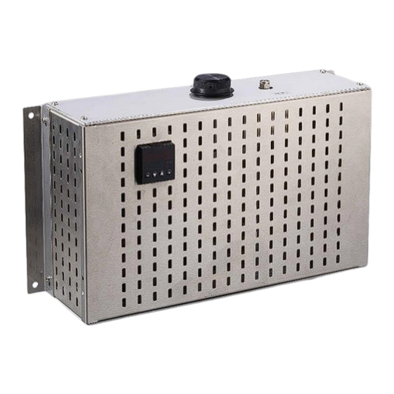
DESCRIPTION Figure 4 shows the conversion unit version CG-2 and CG-2M in the 19”-rack housing. 325 (12.8”) 483 (approx. 19”) 260 (10.24”) (1.73”) 132,5 (3HE) (5.22”) Converter 10 (0.39”) Back view 7 (0.28”) 465.6 (18.33”) 435 (17.13”) ... - Page 17 The M&C gas converters type CG-2 and CG-2M are designed as compact, user-friendly and easy to service 19" plug-in units (figure 4) suitable for mounting in 19" cabinet systems. When fitted with the optional mounting bracket with a vertical swivel-holder (50A3000), the converters can also be wall- mounted.
-
Page 18: Receiving The Cg
RECEIVING THE CG… The CG... converter is a completely pre-installed unit. The standard catalyst cartridge supplied is already installed. • Remove the CG... converter and any accessories carefully from the transport packaging immediately after arrival and check the contents of the delivery against the delivery note; •... -
Page 19: Supply Connections
SUPPLY CONNECTIONS 14.1 HOSE/TUBE CONNECTIONS The gas inlet and outlet hoses/tubes of versions CG-2/-2M are connected on the rear of the converter. Here, the standard executions provides G 1/4" threaded joints. The versions CG-2H-W/-2MH-W as wall mounting execution with heated sample gas inlet and outlet are equipped with a 6 mm tube connector of stainless steel. -
Page 20: Electrical Connections
14.2 ELECTRICAL CONNECTIONS The wrong mains voltage can destroy the device. When connecting, take care that the mains voltage corresponds with the information provided on the type identification plate! For the erection of power installations with rated voltages up to 1000 V, the requirements of VDE 0100 and relevant standards and specifications must be observed! N O T E ! -
Page 21: Starting-Up
If the converter is controlled internally, the bridge between contacts 1 and 6 in the D-sub plug is absolutely necessary! N O T E ! External switching is carried out by the customer using potential-free contacts (see figure 6). If the converter is controlled externally, the bridge between contacts 1 and 6 in the D-sub plug must be removed! N O T E ! With external control, the switch on the front plate of the converter is out of function. -
Page 22: Closing Down
CLOSING DOWN The location at which the converter is mounted must remain frost-free even when the device is switched off! N O T E ! No special measures need to be taken when the converter is taken out of operation for a short period. In order to avoid unnecessary consumption of the catalyst and to ensure that the catalyst is ready for use at short notice, the catalyst temperature should be reduced below 300 °C [572 °F] in the "stand-by"... -
Page 23: Figure 7 Catalyst Life Time Depending On The No
30 l/h 60 l/h 90 l/h 10 15 20 25 30 35 40 45 50 [ppm] 5 vol% O Figure 7 Catalyst life time depending on the NO concentration for varying flow rates and an Oxygen concentration of 5 vol% 30 l/h 60 l/h 90 l/h... -
Page 24: Check Of The Efficiency
17.1 CHECK OF THE EFFICIENCY To check the efficiency of the converter cartridge a test gas with a NO -concentration according to the concentration in the sample gas (e.g. 20 ppm in N ) is necessary. Feed test gas upstream the converter and read measured NO-concentration at the analyzer. Measured NO-concentration [ppm] Efficiency = ------------------------------------------------- x 100 %... -
Page 25: Maintenance
MAINTENANCE Before carrying out maintenance work, make sure that safety measures specific to the installation and process are complied with! Dangerous voltage. Remove mains plug before opening the con- W A R N I N G ! verter’s housing! The CG... converter does not need special maintenance periods. When replacing the catalyst cartridge, it is advisable to change the O-ring-seals provided. -
Page 26: Replacing The O-Ring Seals
18.2 REPLACING THE O-RING SEALS We also recommend replacing the adapter's seals every time that the cartridge is replaced (supplied with each cartridge). Hot catalyst cartridges. Touching the cartridge can lead to very se- W A R N I N G ! vere burns. -
Page 27: Checking For Gas-Tightness
18.3 CHECKING FOR GAS-TIGHTNESS • Connect device to mains supply; • Set temperature controller to ambient temperature; The converter must be cooled down to room temperature in order to check for gas-tightness! N O T E ! • Switch sample gas path to catalyst operation (lower green LED lights up); •... -
Page 28: Use Of The Temperature Controller
USE OF THE TEMPERATURE CONTROLLER 19.1 DISPLAY AND FUNCTION KEYS Process value display, red Set-point display, green PGM key - to select the parameters Decrement key - to alter values Increment key - to alter values ... -
Page 29: Changing The Parameters Of The Temperature Regulator
19.3 CHANGING THE PARAMETERS OF THE TEMPERATURE REGULATOR The programming of the regulator is made on different levels. All important adjustments of the converter are listed in the user level and can be modified after removing the key locking. In order to remove the locking, please proceed as follows: •... -
Page 30: Reset Of The Controller
19.4 RESET OF THE CONTROLLER A reset out of the temperature lock happens with connected mains: • operating simultaneously the keys EXIT A reset only happens in case the actual temperature deviates by < ±10 °C [±18 °F] from the set temper- ature. -
Page 31: Trouble Shooting
TROUBLE SHOOTING The following table is intended to show the possible sources of errors and their rectification Problem/Display Possible Cause Check/Rectification LED’s do not light up Mains ‘ON’ No mains power Valves do not switch over Temperature controller out of Check that mains cable fits properly order (X1);... -
Page 32: Spare Part List
SPARE PART LIST Wear, tear and replacement part requirements depend on specific operating conditions. The recommended quantities are based on experience and are not binding. Converter CG... recommended quantity CG beeing in operation [years] (C) Consumable parts, (R) Recommended spare parts and (a.r. -
Page 33: Figure 11 Wiring Plan Cg-2M, Drawing No.: 2224-5.04.0
Figure 11 Wiring plan CG-2M, Drawing No.: 2224-5.04.0 www.mc-techgroup.com CG-2 | 1.04.00... -
Page 34: Figure 12 Wiring Plan Cg-2Mh-W, Drawing No.: 2224-5.04.4
Figure 12 Wiring plan CG-2MH-W, Drawing No.: 2224-5.04.4 CG-2 | 1.04.00 www.mc-techgroup.com... -
Page 35: Figure 13 Wiring Plan Cg-2H-W, Drawing No.: 2224-5.04.5
Figure 13 Wiring plan CG-2H-W, Drawing No.: 2224-5.04.5 www.mc-techgroup.com CG-2 | 1.04.00...
Need help?
Do you have a question about the CG Series and is the answer not in the manual?
Questions and answers