
Related Manuals for Teledyne Lecroy RP4030


Summary of Contents for Teledyne Lecroy RP4030
- Page 1 Operator’s Manual RP4030 Power Rail Probe GlobalTestSupply www. .com Find Quality Products Online at: sales@GlobalTestSupply.com...
- Page 2 However, clients are encouraged to duplicate and distribute Teledyne LeCroy documentation for internal educational purposes. Teledyne LeCroy is a registered trademark of Teledyne LeCroy, Inc. Windows is a registered trademark of Microsoft Corporation. Other product or brand names are trademarks or requested trademarks of their respective holders.
-
Page 3: Table Of Contents
Introduction ........................ 3 Key Features ....................... 3 Compatibility ....................... 5 Probe Kit ........................6 RP4000-BROWSER Accessory .................. 7 Other RP4030 Accessories ..................8 Specifications ......................10 Nominal Characteristics ..................10 Warranted Characteristics ..................10 Typical Characteristics .................... 10 Physical Characteristics ..................11 Probe Impedence vs. - Page 4 RP4030 Power Rail Probe Care and Maintenance ..................... 30 Cleaning ........................30 Calibration Interval ....................30 Service Strategy ....................... 30 Troubleshooting ....................... 30 Returning a Product for Service ................31 Warranty ........................33 Certifications ......................34 GlobalTestSupply www. .com Find Quality Products Online at:...
-
Page 5: Safety Instructions
Comply with the following safety precautions to avoid personal injury or damage to your equipment: Use only as specified. The probe is intended to be used only with compatible Teledyne LeCroy instruments. Using the probe and/or the equipment it is connected to in a manner other than specified may impair the protection mechanisms. - Page 6 RP4030 Power Rail Probe Keep product surfaces clean and dry. Handle with care. Probe tips are sharp and may cause injury if not handled properly. Comply with the maximum input voltage vs. frequency derating when measuring voltage that includes a high frequency component.
-
Page 7: Introduction
Operator’s Manual Introduction The Teledyne LeCroy RP4030 Power Rail Probe meets the specific requirements of those who need to acquire a low-voltage DC signal as part of testing: Digital power management components such as power management IC (PMIC); • voltage regulator module (VMR); point-of-load (POL) switching regulator; or... - Page 8 The RP4030 eliminates the above tradeoffs and permits more accurate and more convenient DC power/voltage rail probing at very high bandwidths. In the simplified circuit diagram below, the RP4030 portion is highlighted in gray. The input is through a high bandwidth SMA connector, terminated to ground with a 50 kΩ resistor in parallel with a 0.1 μF capacitor.
-
Page 9: Compatibility
PCB. A separate browser tip accessory (the RP4000-BROWSER) is available at additional cost. If desired, the cable and lead connection components may be used separately from the RP4030 probe. This is useful for power sequencing tests where the dynamic range of the DC power/voltage rail exceeds the +/-800 mV rating of the probe. -
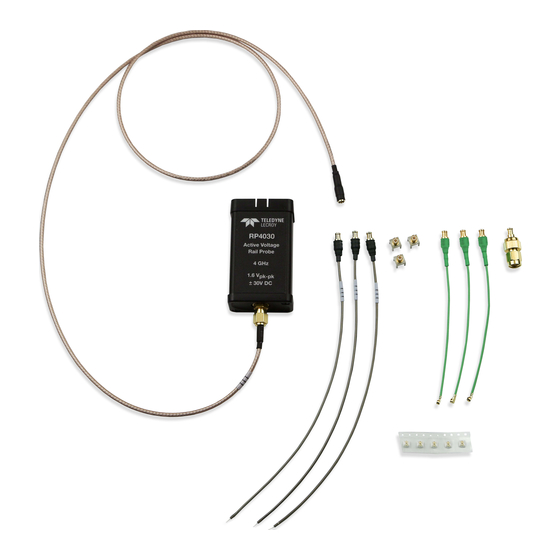
Page 10: Probe Kit
RP4030 Power Rail Probe Probe Kit The following items are shipped with the RP4030 probe. Additional quantities of some parts may be purchased separately using the part number shown in the table. Item Description Part Number Extension Cable SMA to MCX extension cable, 0.9 meters... -
Page 11: Rp4000-Browser Accessory
SMA-to-SMA extension cable, while the other end of this cable terminates at the RP4030 probe, which then terminates at the oscilloscope with 50 Ω coupling with high input impedance. The spring-loaded, hinged ground pin contributes to contact stability while making it easier to reach into dense circuitry. -
Page 12: Other Rp4030 Accessories
RP4030 Power Rail Probe Other RP4030 Accessories Additional quantities of the following accessories may be purchased with the RP4030 or separately. If ordered with the RP4030, they are shipped inside the RP4030 soft carrying case. Item Description Part Number Solder-in Leads... - Page 13 Operator’s Manual Ultra-miniature U.FL Coaxial Cables Three are supplied with the RP4030, and more may be purchased as accessory or replacement items using part number RP4000-MCX-CABLE-UFL. U.FL is a Hirose Electric ultra-miniature connector that is ideal for use in very dense or compact circuits, and is functionally equivalent to IPX and UMCC connectors.
-
Page 14: Specifications
For the most current specifications, see the product datasheet at teledynelecroy.com. Specifications are subject to change without notice. NOTE: The components supplied as part of the RP4030 probe are tested as a system. The performance presented in this manual represents the probe when used with these components. -
Page 15: Physical Characteristics
Operator’s Manual Physical Characteristics RP4030 Weight 620 grams (1.37 lb.) net of packaging material (with all accessories and carrying case) RP4030 Dimensions Probe: 38.1 mm W x 15.9 mm H x 73 mm L (1 1/2” x 5/8” x 2 7/8”) SMA to MCX Cable: 914 mm L (36”) -
Page 16: Frequency Response
RP4030 Power Rail Probe Frequency Response Following is the same data presented with a different magnitude and frequency scale. GlobalTestSupply www. .com Find Quality Products Online at: sales@GlobalTestSupply.com... - Page 17 Operator’s Manual GlobalTestSupply www. .com Find Quality Products Online at: sales@GlobalTestSupply.com...
- Page 18 RP4030 Power Rail Probe GlobalTestSupply www. .com Find Quality Products Online at: sales@GlobalTestSupply.com...
-
Page 19: Operation
Status dialog. Handling the Probe The RP4030 probe is a precision test instrument. Exercise care when handling and storing the probe. Always handle the probe by the probe body or compensation box. Avoid putting excessive strain on or exposing the probe cable to sharp bends. - Page 20 Coupling to DC50Ω. Bandwidth Limit The bandwidth of the RP4030 ranges up to 4 GHz (depending on the lead attachment). If it is desired to limit bandwidth to less than the rating, make a selection from the Cn dialog Bandwidth control.
-
Page 21: Connecting To The Circuit
DC offset drift. To invoke Auto Zero, open the Cn RP4030 dialog and touch Auto Zero. The probe contains an internal relay to disconnect the input from the probe amplifier while Auto Zero is performed, so the probe does not need to be disconnected from the DUT prior to invoking Auto Zero. - Page 22 DC rail. Avoiding Parasitic Inductance All ground connections provided with the RP4030 are very short (browser) or coaxial in nature. This is to ensure any parasitic inductance added to the circuit when the probe connection is made remains low.
- Page 23 Operator’s Manual Connecting to High Impedance Sources The RP4030 is intended to probe low-impedance DC voltage and power rails. The probe’s input impedance is optimized to provide a flat frequency response from DC to rated bandwidth when the source impedance is very low. However, the probe input impedance declines from 50 kΩ...
- Page 24 RP4030 Power Rail Probe Using the Solder-in Lead The MCX cable to solder-in connection is a great solution for probing DC rails on a crowded board. The exposed ~3 mm inner conductor connected to the DC rail and the exposed ~0.5 mm outer conductor is connected to ground, ideally with as short a ground lead as possible.
- Page 25 Operator’s Manual Using the MCX PCB Mounts (Receptacles) The MCX PCB mount receptacle manufacturer is TE Connectivity and the part number is 1061015-1. This part is exceptionally durable and provides the highest bandwidth connection, but it has a larger footprint than other solutions. The center pin is soldered to the signal and one or more of the four posts are soldered to ground.
- Page 26 “pop” the plug out of the receptacle using lever action. Using the RP4000-BROWSER The browser is shipped with a pass-through 0 Ω resistor installed for use with the RP4030. To maintain the high performance capability of the probe in measurement applications, care must be exercised in connecting the probe to the test circuit.
- Page 27 5. Select the proper Attenuation on the input Channel (Cn) setup dialog. NOTE: The RP4030 will not work properly when a resistor other than 0 Ω is installed in the RP4000-BROWSER. If the resistor is changed and is not reverted to 0 Ω prior to using the browser with the RP4030, the voltages displayed on the oscilloscope will be incorrect.
-
Page 28: Performance Verification
RP4030 Power Rail Probe Performance Verification This procedure can be used to verify the warranted characteristics of an RP4030 probe. It tests: LF Attenuation Accuracy • Offset Accuracy • The recommended calibration interval for the RP4030 is one year. Perform the complete performance verification procedure as the first step of annual calibration. -
Page 29: Functional Check
2. Verify that the C1 RP4030 dialog tab appears behind the C1 setup dialog. This confirms the probe is sensed. 3. Open the C1 RP4030 dialog and touch Auto Zero then OK to Auto Zero the probe. 4. Confirm that the message "Performing Auto Zero on RP4030.." is displayed on the message bar and that no error messages appear. - Page 30 RP4030 Power Rail Probe Performance Verification Test Setup GlobalTestSupply www. .com Find Quality Products Online at: sales@GlobalTestSupply.com...
- Page 31 2. Set both DMMs to measure DC Volts. 3. Set the function generator to output DC Volts. 4. Open the oscilloscope C1 setup dialog (not the C1 RP4030 dialog) and set Coupling to ground (GND). Ensure that there is 0.00 mV Offset on C1.
- Page 32 NOTE: Make sure all values are converted to Volts before calculating. Record the result in Step 16 “Offset Error” on the test record. This completes the Performance Verification of the RP4030. Complete and file the Test Record as required to support your internal calibration procedure.
-
Page 33: Rp4030 Test Record
Operator’s Manual RP4030 Test Record Serial Number: _____________________________________________ Asset/Tracking Number: _____________________________________________ Date: _____________________________________________ Technician: _____________________________________________ Equipment Model Serial Number Calibration Due Date Digital Multimeter 1 Digital Multimeter 2 Oscilloscope Function Generator N/A* * The function generator is used for making relative measurements. The output of the generator is measured with a DMM or oscilloscope. -
Page 34: Care And Maintenance
(A Performance Verification procedure is included in this manual.) Service Strategy The RP4030 probe utilizes fine pitch surface mount devices, making it impractical to repair in the field. Defective probes must be returned to a Teledyne LeCroy service facility for diagnosis and exchange. -
Page 35: Returning A Product For Service
4. Package the probe case in a cardboard shipping box with adequate padding to avoid damage in transit. 5. Mark the outside of the box with the shipping address given to you by Teledyne LeCroy; be sure to add the following: ATTN: <RMA code assigned by the Teledyne LeCroy>... -
Page 36: Warranty
Spare parts, replacement parts and repairs are warranted for 90 days. In exercising its warranty, Teledyne LeCroy, at its option, will either repair or replace any assembly returned within its warranty period to the Customer Service Department or an authorized service center. -
Page 37: Certifications
RP4030 Power Rail Probe Certifications Teledyne LeCroy certifies compliance to the following standards as of the date of publication. For the current certifications, see the EC Declaration of Conformity shipped with your product. EMC Compliance EC D - EMC ECLARATION OF... - Page 38 The probe is subject to disposal and recycling regulations that vary by country and region. Many countries prohibit the disposal of waste electronic equipment in standard waste receptacles. For more information about proper disposal and recycling of your Teledyne LeCroy product, visit teledynelecroy.com/recycle. ESTRICTION OF AZARDOUS UBSTANCES The product and its accessories conform to the 2011/65/EU RoHS2 Directive.
Need help?
Do you have a question about the RP4030 and is the answer not in the manual?
Questions and answers