
Related Manuals for Küschall Compact SA


Summary of Contents for Küschall Compact SA
- Page 1 Küschall® Compact Compact SA / Compact FF en Active Wheelchair Service Manual PROVIDER: Keep this manual. The procedures in this manual MUST be performed by a qualified technician.
- Page 2 ©2019 Invacare Corporation All rights reserved. Republication, duplication or modification i n w hole o r i n p art i s p rohibited w ithout p rior written permission from Invacare. Trademarks are identified by ™ and ®. All trademarks are owned by or licensed to Invacare Corporation or its subsidiaries unless otherwise noted.
-
Page 3: Table Of Contents
Contents 6.6.1 Installing the Clothes-Guard / Mudguard ..33 6.6.2 Adjusting the Clothes-Guard / Mudguard ..33 6.6.3 Installing the removable Mudguard ....33 1 General . -
Page 4: General
Küschall® Compact personal injury or property damage. See the information 1 General below for definitions of the signal words. WARNING 1.1 Introduction Indicates a hazardous situation that could result in serious injury or death if it is not This document contains important information about avoided. -
Page 5: Safety
Safety 2 Safety IMPORTANT! Some replacement parts are only available as a kit. Always use the complete new kit when replacing a part. 2.1 General Safety Information – Spare parts can be ordered from Invacare. Refer to your local Invacare website to access WARNING! the electronic spare parts catalogue (ESPC). - Page 6 Küschall® Compact Fastening with hexagon socket bolts Hexagon socket bolts are not designed to withstand an excessive application of force. When tightening or undoing a hexagon socket bolt, force should be applied to the nut wherever possible to avoid damaging the bolt. Tightening and undoing Turn the nut using a socket spanner (only use an open-end spanner if there is insufficient space), using the Allen key...
-
Page 7: Product Overview
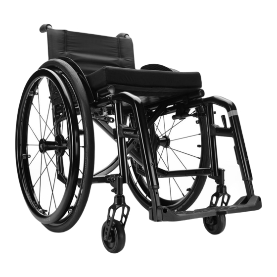
Product Overview 3 Product Overview 3.1 Main parts of the wheelchair A Back B Clothes-guard C Seat D Frame E Footrest F Castor fork with castor wheel G Parking brake H Rear wheel with handrim 3.2 Dimensions A Seat depth (SD) 320 – 500 mm, in increments of 20 mm B Backrest angle 82°/86°/90°/ 94°/98°/102°... -
Page 8: Servicing
Küschall® Compact 4 Servicing ☐ ☐ Has the product been cleaned and disinfected? ☐ ☐ Is the identification label easily readable and is it securely mounted on the product? 4.1 Inspection checklist ☐ ☐ Is the product accompanied by the latest revision of the user manual? General inspection ☐... -
Page 9: Reconditioning
Reconditioning 5.2 Disinfection 5 Reconditioning Information on recommended disinfectants and methods can be found on https://vah- 5.1 Cleaning online.de/en/for-users. IMPORTANT! 1. Wipe down all generally accessible surfaces with a soft – The product does not tolerate cleaning in cloth and ordinary household disinfectant. automatic washing plants, with high-pressure 2. -
Page 10: Instructions
Küschall® Compact 6 Instructions 6.1 Frame Overview A Rear frame = 13 Nm = 7 Nm B Retaining lever = 4 Nm C Cross D Front frame = 13 Nm = 7 Nm E Upper connection tube F Lower connecting tube G Seat locking mechanism H Longitudinal stopping bolts... -
Page 11: Replacing The Retaining Lever
Instructions 1. Disassemble brakes. 2. Loosen and remove bolts D and D on both sides. (On abduction frames, the connecting tube F is welded onto the front frame; in this case loosen A and D 3. Pull out front frame D to the front. 4. -
Page 12: Cutting The Rear Frame To Length
Küschall® Compact 1. Remove the old bolt connection from the cross-brace. 2. Lubricate both sides of distance part E slightly with Molykote TP42 and remove excess grease. 3. Re-assemble the cross-brace using only the new assembly kit (SP1537689) containing bolt A with washer, spacer B, spring washer C, safety cap nut D and distance part E. - Page 13 Instructions Backrest height (RH) Height-adjustable push handle, integrated straight x [mm] lumbar x [mm] 1659353-A...
-
Page 14: Seat
Küschall® Compact 6.2 Seat 6.2.1 Front Seat-to-Floor Height (FSTF) Options for changing the front seat height: • Replace the castor wheel with larger or smaller one or fit it at another position on the castor fork, see 6.7.1 Replacing the Castor Wheel, page 40. •... -
Page 15: Seat Width (Sw)
Instructions Rear seat-to-floor height with respect to the rear wheels and positioning on the frame Rear seat Rear wheel size [inch] height (RSTF) 22’’ 24’’ 25’’ 26’’ [mm] — — — RSTF 370 — — — RSTF 380 — — RSTF 390 —... - Page 16 Küschall® Compact ■□□ Allen key (3 mm) 1. Loosen bolt in seat locking mechanism A. Screw out the bolt only to the extent that the seat locking mechanism can be turned as otherwise the threaded insert can move and is then difficult to re-position.
-
Page 17: Backrest
Instructions 6.3 Backrest 6.3.1 Backrest Height The backrest height can be changed by installing the telescopic tubes in another position in the backrest tubes. If this setting option is insufficient, the telescopic tubes can be replaced. 6.3.2 Adjusting the Height of standard Backrests ■■□... -
Page 18: Installing An Angle-Adjustable Backrest
Küschall® Compact Position Deviation from Angle between standard backrests backrest and seat 12° 102° 8° 98° 4° 94° 0° 90° -4° 86° -8° 82° -12° 78° 6.3.5 Installing an angle-adjustable Backrest ■■□ Allen key (3 mm, 4 mm, 5 mm) / Socket spanner (8, 10) / Open-end spanner (10) Shorter rear frame (variant III) required. -
Page 19: Installing The Joint For A Folding Backrest
Instructions 1. Remove the backrest cushion B and push the hook and loop bands C upwards, until the backrest joint A is invisible. 2. Remove the bolt D. 3. Slightly loosen bolt E. 4. Set the desired backrest angle, insert the bolt D in the nearest hole and tighten. -
Page 20: Replacing Push Handles / Replacing Push Handles And Backrest
Küschall® Compact 6.3.8 Replacing Push Handles / Replacing Push Handles and Backrest If the push handles are replaced with a different type of push handles, e.g. height-adjustable ones, it can happen that the rear frame must also be replaced. Changing the backrest height can also mean that the configuration of the hook and loop bands must be changed. 6.3.9 Installing standard Push Handles ■■□... -
Page 21: Installing Angle-Adjustable Backrest With Height-Adjustable Push Handles
Instructions 1. Secure the telescopic tube B to the rear frame A at the required height using bolt G, washer and nut. 2. Press the cover cap F onto the end of the telescopic tube. 3. Push the hook and loop bands C onto the telescopic tube. -
Page 22: Installing The Stabilisation Bar
Küschall® Compact 1. Remove the old foldable push handle. 2. Pull down the backrest cover F on the telescopic tube, until its hole B is uncovered. IMPORTANT! – Make sure that the threaded insert E (part no. 1580450) supplied with the new push handle is used for assembly. 3. -
Page 23: Backrest Parts For Adjustable Backs With Respect To Backrest Height
Instructions 6.3.15 Backrest Parts for adjustable Backs with respect to Backrest Height Fixed Backrest with standard/mini Push Handles, foldable Push Handles* or without Push Handles Backrest height (RH) with respect to cover, backrest tubes, bands Cover Telescopic Bands (without Bands (with [mm] tube A stabilisation bar,... - Page 24 Küschall® Compact Fixed or angle-adjustable Backrest with height-adjustable Push Handles, rear set Backrest height (RH) with respect to cover, backrest tubes, bands Cover Telescopic tube Bands (without Bands (with [mm] A (straight/ stabilisation bar, stabilisation bar, lumbar) end band C = 10 end band C = 5 —...
- Page 25 Instructions Angle adjustable Backrest with standard/mini Push Handles, foldable Push Handles* or without Push Handles Backrest height (RH) with respect to cover, backrest tubes, bands Cover Telescopic Bands (without Bands (with [mm] tube A stabilisation bar, stabilisation bar, end band C = 10 end band C = 5 —...
- Page 26 Küschall® Compact Angle adjustable Backrest with height-adjustable Push Handles, integrated Backrest height (RH) with respect to cover, backrest tubes, bands* Telescopic tube Cover C Backrest tube B Push handle A [mm] *For bands configuration, see 1 table „Angle adjustable backrest with standard push handles“. 1659353-A...
- Page 27 Instructions Foldable Backrest with standard/mini Push Handles, foldable Push Handles or without Push Handles Backrest height (RH) with respect to cover, backrest tubes, bands Cover Telescopic Bands (without Bands (with [mm] tube A stabilisation bar, stabilisation bar, end band C = 10 end band C = 5 —...
- Page 28 Küschall® Compact Foldable Backrest with height-adjustable Push Handles, rear set Backrest height (RH) with respect to cover, backrest tubes*, bands Cover Telescopic Bands (without Bands (with [mm] tube A stabilisation bar, stabilisation bar, end band C = 10 end band C = 5 —...
- Page 29 Instructions For foldable backrests additionally a band is fixed close to the backrest joint. The band is of different length according to the seat width (SW): SW 280 mm - 360 mm = short / SW 380 mm - 440 mm = medium / SW 460 mm - 500 mm = long 1659353-A...
-
Page 30: Legrests
Küschall® Compact 6.4 Legrests Legrests with angle measurements of 70°, 80° and 90° are available. 6.4.1 Replacing the locking Mechanism ■□□ Torx screwdriver (10) / Allen key (3 mm, 5 mm) 1. Screw off the unlocking lever A manually. 2. Remove the hinge pin B. 3. -
Page 31: Replacing The Footrest (One-Piece Footrest)
Instructions 6.5.2 Replacing the Footrest (One-piece Footrest) ■□□ Allen key (4 mm) / Socket spanner (8 mm) 1. Remove bolts, washers and nuts A on both sides. 2. Pull the footrest out of the frame tubes. 3. Insert new footrest. 4. -
Page 32: Replacing The Footrest (Two-Piece Footrest)
Küschall® Compact 6.5.5 Replacing the Footrest (Two-piece Footrest) ■□□ Allen key (4 mm) / Socket spanner (8 mm) 1. Remove bolts, washers and nuts A. 2. Remove the footrests B from the frame. 3. Insert new footrests into the frame and position at the required height. -
Page 33: Sideparts
Instructions 6.6 Sideparts 6.6.1 Installing the Clothes-Guard / Mudguard ■■□ Allen key (3 mm) / Socket spanner (8) 1. Install the side fastenings A onto the frame D using bolts, washer and nuts C. 2. Install clothes-guard/mudguard B with bolts, washers and nuts E onto the side fastenings. -
Page 34: Clothes-Guard / Mudguard Sizes
Küschall® Compact 1. Install the holder C to the frame using the screw connections A and B and then reinstall the rear wheel. 2. Slightly loosen the crub screw D on the adjustment plate E and slide it along the mudguard carrier until the mudguard is at the desired height. -
Page 35: Installing The Hemi Armrest With Holder
Instructions — — — — — — — — — — — — — — — — — — — — — — — — — — — — — — Mudguard mounted fix Mudguard (mounted fix) with respect to the position of the rear wheels with standard adapter plate (Pos. 1 to 4) RSTF Rear wheel 22’’... - Page 36 Küschall® Compact Installing the guiding part 1. Install the retaining bracket H around the rear frame L to the clamping block A using bolt I. 2. Install the guiding part B to the clamping block using washer C, sunk sleeve D and bolt E. 3.
-
Page 37: Installing The Küschall Armrest
Instructions 5. Reinstall the rear frame parts, see 6.1.1 Replacing the Rear Frame, page 10. 6. Insert nuts U into the armrest holder and install bolts R with spring washer S. Adjust the bolts R so that the armrests engages optimally. -
Page 38: Height-Adjustable
Küschall® Compact Installing/Removing the Armrest, T-Armrest Pad and Cover Installing 1. Install the armrest cover to the armrest assembly. 2. Insert the armrest assembly into the joint K and swivel it downwards so that it engages into the armrest holder A. 3. -
Page 39: Installing The Tubular Armrest (Swivelling)
Instructions 1. Fit the side fastening element C with bolts A and B. 2. Insert side rest into the fastening element. Adjusting the height 1. Slightly loosen the crub screw D on the adjustment plate E and slide it along the armrest carrier until the armrest is at the desired height. -
Page 40: Castors
Küschall® Compact 6.7 Castors 6.7.1 Replacing the Castor Wheel ■■□ Allen key (3 mm) 1. Remove the bolts A with washers B and pull out the wheel axle C. 2. Remove castor wheel D from the castor fork E and replace with a new one or move to a new position. -
Page 41: Setting The Steering Error Angle
Instructions 1. Remove the castor wheel, see 6.7.1 Replacing the Castor Wheel, page 40. 2. Remove bolt A, washer B, the castor fork D with bearings C and part E from the clevis pin F. 3. Replace the castor fork with bearings and reinstall in revers order. -
Page 42: Frame
B = 10 Nm 6.7.5 Installing/Shifting the Castor Fork Supporter on the Frame ■□□ Allen key (5 mm) / Socket spanner (8 mm) Compact SA Low-mounted supporter: 1. Remove nuts, washers and bolts A. 2. Remove round nut D from the frame tube. -
Page 43: Rear Wheels
Instructions Compact SA Hemi Low-mounted supporter: 1. Remove nuts, washers and bolts A. 2. Remove round nut D from the frame tube. 3. Replace the castor fork supporter B on the frame C. 4. Reinsert round nut D into the frame tube. -
Page 44: Adjusting The Rear Seat-To-Floor Height (Rstf)
Küschall® Compact 6.8.1 Adjusting the rear Seat-to-Floor Height (RSTF) ■□□ Allen key (5 mm) / Socket spanner (10) 1. Loosen bolt A. 2. Remove bolts B, washer and nut D and move the adapter plate C to the required position. 3. -
Page 45: Changing The Wheel Camber
Instructions 1. Remove the standard adapter plate A and counterpiece B by removing bolt C, bolts D, washer and nut E from the rear frame. 2. Position the adapter plate for the rear wheel extension F at the required height and tighten securely on the counterpiece G using bolts H and bolt, washer and nut I. -
Page 46: Adjusting The Removable Axle
Küschall® Compact same at the front and the back (x = y) – measured at the height of the center of the axle. At the same time, the distance between the individual wheels and the relevant side frame can be checked for conformity and adjusted if necessary. -
Page 47: Replacing A Solid Tire
Instructions 1. Remove the rear wheel and release any air from the inner tube. 2. Lift one tyre wall away from the rim using a bicycle tyre lever. Do not use sharp objects such as a screwdriver which could damage the inner tube. 3. -
Page 48: Parking Brakes
Küschall® Compact 6.9 Parking brakes 6.9.1 Installing the parking brake ■■□ Allen key (5 mm) 1. Position the brake holder B around the front frame tube C. 2. Place the brake D in the brake holder. 3. Screw the bolt A with washer into the brake assembly but do not tighten. -
Page 49: Installing/Adjusting The Drum Brake
Instructions 6.9.3 Installing/Adjusting the Drum Brake ■■■ Allen key (4 mm) / Phillips screwdriver / Open-end spanner (9 mm) / Socket spanner (10 mm, 22 mm) / Wrench (4 mm) 1. Remove standard adapter plate and replace with adapter plate for drum brake, see 6.8.8 Installing the Adapter Plate for the Drum Brake, page 46. -
Page 50: Adjusting The Height Of The Antitipper
Küschall® Compact 1. Install the adaptation support A with bolts, washers and nuts B to the adapter plate C. B = 13 Nm 6.10.2 Adjusting the height of the antitipper ■□□ Allen key (4 mm) / Socket spanner (8) 1. Loosen bolt B and remove the upper end C of the antitipper and the holder D. -
Page 51: Installing The Tipper Aid
Instructions 6.10.3 Installing the tipper aid ■□□ Allen key (5 mm) / Socket spanner (10) 1. Install the adaptation support A with bolt B to the adapter plate C. 2. Push in spring clip D and push the tipper aid into the adaptation support. -
Page 52: Adjusting The Height Of The Cane Holder
Küschall® Compact 6.10.6 Adjusting the height of the cane holder ■□□ Flat-head Screwdriver 1. To adjust the height, remove cap B and, e.g. using a screwdriver, compress the spring A inside the tube and push into the required position. 6.10.7 Installing the transit wheels ■□□... -
Page 53: Installing The Posture Belt
Instructions 1. Install the adapter plate D to the frame M using bolt E and bolts F with washer and nut G. 2. Install the quick-release adapter I with washer J, sleeve K and nut H to the adapter plate on both sides. 3. -
Page 54: Attaching The Snap Hook Symbol Labels
Küschall® Compact 1. If not present, drill a hole D on both sides through the frame B. 2. Mount the steel strap A using bolts, washers and nuts C through the holes D on both sides. C = 4 Nm WARNING! Risk of injury due to incorrect installation –... - Page 55 Notes...
- Page 56 Invacare distributors Asia: Australia: Belgium & Luxemburg: Danmark: Invacare Asia Ltd. Invacare Australia Pty. Ltd. Invacare nv Invacare A/S 1 Lenton Place, North Rocks NSW 2151 1 Lenton Place, North Rocks NSW 2151 Autobaan 22 Sdr. Ringvej 37 Australia Australia B-8210 Loppem DK-2605 Brøndby Phone: (61) (02) 8839 5333...
Need help?
Do you have a question about the Compact SA and is the answer not in the manual?
Questions and answers