Table of Contents
Advertisement
Quick Links
Advertisement
Table of Contents

Related Manuals for T-Drill T-35


Summary of Contents for T-Drill T-35
- Page 2 Your local representative is: Copyright © 2010 T-DRILL Oy. All rights reserved. This manual, or parts thereof, may not be reproduced in any form or by any means, nor translated into any other language without a written permission of T-DRILL Oy.
-
Page 3: Table Of Contents
4. Transport, Handling and Storage ........15 4.1 T-35 .................. 15 5. Commissioning ..............16 5.1 T-35, Detachment and attachment of the connecting cord ..16 5.2 T-35 start-up check .............. 16 6. Operation of the machine ..........17 ... - Page 4 I N S T R U C T I O N M A N U A L...
-
Page 5: How To Use The Instruction Manual
This instruction manual includes instructions for set-up, operation and maintenance of the T-DRILL T-35 tee forming machine. This book also includes instructions on how to use and select T-DRILL heads for hand tools. NOTE! Before carrying out any actions, read chapter 2 ”Safety Instructions”. -
Page 6: Symbols On The Tool
I N S T R U C T I O N M A N U A L 1.2 Symbols on the tool The following list identifies the symbols on the tool. Read the instruction manual carefully before using this tool. Double Insulated 130°... -
Page 7: General Safety Instructions
T-DRILL tee forming unit. Detaching the power unit will damage the alignment produced in factory. NOTE! - The T-DRILL T-35 is designed for use with power unit T-DRILL has chosen. Using any other power units with the T-DRILL T-35 tee forming unit is not permitted. -
Page 8: Personal Safety
I N S T R U C T I O N M A N U A L with earthed (grounded) power tools. Unmodified plugs and matching outlets will reduce risk of electric shock. b) Avoid body contact with earthed or grounded surfaces, such as pipes, radiators, ranges and refigerators. -
Page 9: Power Tool Use And Care
T-35 T E E F O R M I N G M A C H I N E e) Do not overreach. Keep proper footing and balance at all times. This enables better control of the power tool in unexpected situations. -
Page 10: Service
2.5 Service Repairs must be carried out by an authorised T-DRILL service agent – This electric tool complies with the relevant safety requirements. Repairs should be carried out only by certified persons using original spare parts;... - Page 11 T-35 T E E F O R M I N G M A C H I N E Never carry the tool with your finger on the trigger. Be careful to avoid accidental starting of the machine when handling it.
-
Page 12: T-Drill T-35, General
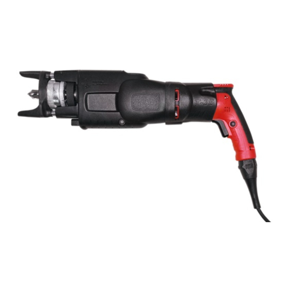
T-DRILL T-35 is a special tool designed for forming tees mechanically in copper tubes typically found in domestic, commercial and industrial tubing systems. The T-35 extrudes an outlet in the run tube and the branch tube can be joined to the outlet by brazing. -
Page 13: Information About Accessories
1. Notcher, 2. Gauge block, 3. Ring 3.3.2 Gauge block and ring The correct size settings of the T-DRILL head for various tube sizes can easily be checked with the gauge block. The size range is NS 1/4"-1" with the gauge block and 1¼” with the ring. -
Page 14: Operating Range Of The Machine
I N S T R U C T I O N M A N U A L 3.4 Operating Range of the Machine The T-DRILL T-35 is intended for forming a tee in copper tube. The branch tube is joined to the run tube by brazing. -
Page 15: Transport, Handling And Storage
6.5” (165mm) x 14.2” (360mm) (w x h x d). Depending on the accessories included, the weight of the box is between 29 - 49 lbs (13 and 23 kg) . Storage Keep the T-35 stored in a cool, dry place, covered to protect it from dust, etc. -
Page 16: Commissioning
I N S T R U C T I O N M A N U A L 5. Commissioning 5.1 T-35, Detachment and attachment of the connecting cord The T-35 power unit is equipped with a connecting cord which allows quick changeovers in field conditions. Detachment and attachment of the connecting cord Detachment of the cord 1. -
Page 17: Operation Of The Machine
T E E F O R M I N G M A C H I N E 6. Operation of the machine 6.1 Description of control devices 6.1.1 T-DRILL T-35 Control devices: 1. Trigger, 2. Feed mechanism engagement lever NOTE! Use maximum speed of rotation when drilling and forming the outlet... - Page 18 I N S T R U C T I O N M A N U A L Feed mechanism lever The feed mechanism lever is situated near the chuck-ring. The feed mechanism is engaged (on) when the lever is turned down, i.e. as shown on the illustration.
-
Page 19: Selection And Adjustment Of The T-Drill Heads
6.2 Selection and adjustment of the T-DRILL heads 6.2.1 Identification of the T-DRILL head The size of the T-DRILL head is stamped on the cover plate: Identification: 1. Actual size in millimetres, 2. Nominal size in inches (NS), 3. The ordering and identification number of the T-DRILL head... - Page 20 Each T-DRILL head is adjusted at the factory to correspond to the nominal size stamped on the cover of each T-DRILL head. Changing the tube sizes or the way of joining may require adjustment of the T-DRILL head in order to achieve the right joint.
- Page 21 You can check the forming pin span diameter T with an adjusting ring (option) Depending on the size of the T-DRILL head, the forming pin span T should be 0,020” – 0,055” (0,5 – 1,4mm) bigger than the branch pipe’s outer diameter (O.D.)
-
Page 22: Chucking The T-Drill Head
To insert the T-DRILL head into the chuck, rotate the locking ring (1) clockwise and slide the T-DRILL head (2) shaft into the machine. Release the locking ring. Rotate the T-DRILL head (3) in the chuck until it locks. Make sure the T-DRILL head is tightly chucked. -
Page 23: Tee Forming Process With The T-Drill T-35
T-35 T E E F O R M I N G M A C H I N E 6.4 Tee forming process with the T-DRILL T-35 Since the process may be new to you, we recommend that you read the following instructions carefully and then practice a few times on some pieces of scrap tubing. - Page 24 Press the tube support with the thumb against the tube and twist the machine counterclockwise at the handle of the tool. This centers the T-DRILL head onto the tube. 8. Start the tool by pressing the trigger drill...
- Page 25 The outlet is now ready. IMPORTANT! Release the drill trigger as soon as the T-DRILL head clears the rim of the outlet. NOTE! Never attempt to “help” the tool by pulling it out of the tube. This...
-
Page 26: Annealing Of Tube
3. Drill a pilot hole into the tube. 4. Start the tee-forming process. NOTE! Always lubricate the T-DRILL head before drilling and tee-forming. NOTE! T-DRILL recommends that tubes are annealed whenever the formed outlet is as large as the tube itself. The tube should also be annealed if the machine does not have sufficient power to form the tee. -
Page 27: Maintenance
T E E F O R M I N G M A C H I N E 7. Maintenance 7.1 The maintenance of the T-DRILL T-35 The T-DRILL T-35 is prelubricated and does not need special attention for maintenance. Clean dust and dirt from tool vents. NOTE! All other maintenance measures that need to be... -
Page 28: Replacement Of The Forming Pins
(4) will slide from the shank. The forming pins can now be replaced. Reassemble the T-DRILL head using new forming pins and adjust to the correct outlet diameter. 1. Screws, 2. conical cover, 3. cone, 4. forming pins... -
Page 29: Trouble-Shooting
T-DRILL head carefully before every outlet forming operation Lubricant not suitable for the material. Consult your local T-DRILL representative The wall thickness of the tube exceeds maximum Consult the capacity charts permitted thickness. The size of the tee Dirt stuck to the surface or the Clean the forming pins. - Page 30 If you cannot resolve the problem with the help of our trouble-shooting information, please get in touch with your own T-DRILL representative. State the following details: • Name of your company • Your own name and function in the company •...
-
Page 31: Disposal
T E E F O R M I N G M A C H I N E 9. Disposal Disposal of the T-DRILL machine Various kinds of metals, plastics and lubricants have been used in the manufacture of the T-DRILL machines. Dispose of your T-DRILL machine according to federal, state and local regulations. -
Page 32: Warranty
(other than normal wear and tear) for a period of one (1) year from date of shipment. If within this period any T-35 machine is found to be defective and the defects are acknowledged by T-DRILL, such product shall be repaired or replaced. Such repair or replacement shall be T-DRILL’s sole obligation, whereas the buyer’s only... -
Page 33: Supplement
This thickness is not to be exceeded. Capacity chart for forming tees in copper tubes T-35 capacity and instruction chart for M, L, & K tubing Run Size 1” 1½””... - Page 34 I N S T R U C T I O N M A N U A L 1. Extend tube supports, place tube supports on either side of tube. Drill pilot hole, extend forming pins, engage feed mechanism, form tee (Use high speed).
-
Page 35: Notcher
T-35 T E E F O R M I N G M A C H I N E 12. Notcher 12.1 General 12.1.1 Purpose of the tool The tube end notcher is a device for the preparation of the end of the tube before insertion into the T-branch collar. -
Page 36: Operation Instructions
I N S T R U C T I O N M A N U A L 12.1.2 Operating range In /NS ½ 14-16 ¾ 1¼ 1½ 12.1.3 Dimensions Measure Length 16,5 Operational width Height, lever in upright position Height, lever in down position Weight 15 lbs 6,8 kg... -
Page 37: Maintenance
T-35 T E E F O R M I N G M A C H I N E 12.3 Maintenance 12.3.1 Loose holder pins In case holder pins are loose, unscrew both screws on the name plate, lift up name plate and tighten the set screw for the holder pin with a 3 mm hex wrench. - Page 38 I N S T R U C T I O N M A N U A L 12.3.5 How to replace upper die Remove upper die assy as above (point 12.3.4). To remove name plate, unscrew the two screws and lift off name plate. Secure tube shaft to vise. Only loosen lock screws of holder pins with 3mm wrench and remove lock screw of 2”...
-
Page 39: Spare Parts List
T-35 T E E F O R M I N G M A C H I N E 13. Spare parts list 13.1. T-DRILL T-35 Part No. Complete Assembly 5330624 T-35 120V USA Item Part No. Description 5330628 Power unit 120V USA... -
Page 40: Power Unit
I N S T R U C T I O N M A N U A L 13.2 Power unit Part No. Complete Assembly 5330628 Power unit 120V USA Item Part No. Description 8000226 Hand drill 120V USA 4330016 Gearwheel 6330604 Bushing 6330622... - Page 41 T-35 T E E F O R M I N G M A C H I N E Notes...
-
Page 42: The T-Drill Tee Forming Unit
I N S T R U C T I O N M A N U A L 13.3 The T-DRILL Tee Forming Unit... - Page 43 T-35 T E E F O R M I N G M A C H I N E TheT-DRILL Tee Forming Unit Part No. Complete Assembly 5330174 T-DRILL Tee Forming Unit Item Part No. Description 5330171 Housing 5330138 Lead screw...
-
Page 44: T-Drill Head
I N S T R U C T I O N M A N U A L 13.4 T-DRILL Head Tee Size ∅ mm Nominal Tee Size ∅ in 1/1/4 Order No. 5310399 5310400 5310401 5310402 5310403 5310404 5310411 Item Description Part No. -
Page 45: Optional Equipment
T-35 T E E F O R M I N G M A C H I N E 13.5 Optional Equipment Item Part No. Description 5090294 Notcher ND-54 3310461 Gauge block 4050165 Ring 9010205 Bottle of lubrication... -
Page 46: Notcher Nd-54
I N S T R U C T I O N M A N U A L 13.6 Notcher ND-54 Item Part No. Description 4090275 Base 2090276 Body plate 2090277 Lower die 3090278 Upper die 4090279 Support plate for upper 3090280 Holder pin plate 4090298... - Page 47 T-35 T E E F O R M I N G M A C H I N E 13.6 Notcher ND-54...
-
Page 48: Ordering Spare Parts
I N S T R U C T I O N M A N U A L 14. Ordering spare parts When ordering spare parts, please state the following details: -The type code of the machine -Manufacturing code of the machine -The part number -A description of the part -The quantity of the parts required... - Page 49 T-35 T E E F O R M I N G M A C H I N E...
Need help?
Do you have a question about the T-35 and is the answer not in the manual?
Questions and answers