Table of Contents
Advertisement
Advertisement
Table of Contents

Related Manuals for T-Drill T-60


Summary of Contents for T-Drill T-60
- Page 2 Your local representative is: Copyright © 2002 T-DRILL Oy. All rights reserved. This manual, or parts thereof, may not be reproduced in any form or by any means, nor translated into any other language without a written permission of T-DRILL Oy.
-
Page 3: Table Of Contents
4. Transport, Handling and Storage ............. 14 4.1 T-60 ................... 14 5. Preparing before use ................. 15 5.1 T-60, Detachment and attachment of the connecting cord ..15 5.2 T-60:s start-up check ..............15 6. The operation of the machine ............16 6.1 Description of the control devices .......... - Page 4 I N S T R U C T I O N M A N U A L...
-
Page 5: Notes On The Use Of The Instruction Manual
DANGER! Will or may cause a serious accident or death, if the right precautionary measures have not been taken. This instruction manual includes instructions for set-up, operation and maintenance of the T-DRILL T-60 tee forming machine. This book also includes instructions on how to use and select T-DRILL heads for hand tools. -
Page 6: Symbolism
I N S T R U C T I O N M A N U A L 1.2 Symbolism The following list defines the symbols on the tool. Read the instruction manual carefully before using this tool. Double Insulated 130° Thermally protected to 130°C) Warning! Do not throw to trash. -
Page 7: General Safety Instructions
NOTE! Never detach the MILWAUKEE power unit from the T-DRILL tee forming unit. Detaching the power unit will damage the alignment made in factory. NOTE! - The T-DRILL T-60 is designed for use with MILWAUKEE power unit. -
Page 8: Safety Instructions For Tool
I N S T R U C T I O N M A N U A L 2.2 Safety instructions for tool Store idle tools – when not in use, tools should be stored in dry, high, or locked-up place, out of the reach of children. Don’t force tool –... - Page 9 Have defective switches replaced by an authorised service. Do not use tool if switch will not turn it on and off. Have your tool repaired only by T-DRILL – This electric tool is in accordance with the relevant safety requirements. Repairs should be carried out only by certified persons using original spare parts;...
-
Page 10: Safety Instructions For Tee Forming
I N S T R U C T I O N M A N U A L 2.3. Safety instructions for tee forming Do not touch the rotating tool when the work cycle is on. When fixing the machine to the tube, be careful not to leave your fingers between the machine and the tube When handling the tools, be careful with the cutting blades. -
Page 11: T-Drill T-60, General
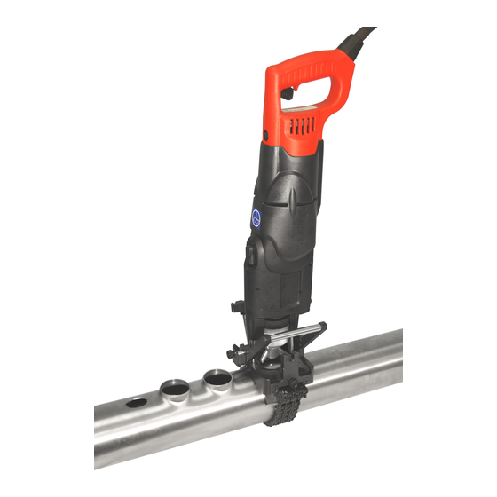
The T-DRILL T-60 is a special tool intended for mechanically forming tees in copper tube typically found in domestic, commercial and industrial tubing systems. The T-60 extrudes in the run tube an outlet, to which the branch tube can be joined by brazing. -
Page 12: Information About Accessories
Gauge Block and rings Correct size settings of the T-DRILL head for various tube sizes can easily be checked with the gauge block. The range of size is NS 1/4"-1" with the gauge block;... -
Page 13: Operating Range Of The Machine
The outlet size range of T-60 is NS 1/2" to 2" (10 – 54 mm). The diameter of the run tube can be 1/2 " to 4" (15 – 108 mm). The maximum wall thickness of the tube to be branched depends on the tube diameter and the size of the T-DRILL head used. -
Page 14: Transport, Handling And Storage
4. Transport, Handling and Storage 4.1 T-60 The T-60 is delivered in a transport box, dimensions 25.2” (640mm) x 6.5” (165mm) x 14.2” (360mm) (w x h x d). The weight of the box is, depending on the accessories, between 29 - 49 lbs (13 and 23 kg) . -
Page 15: Preparing Before Use
T E E F O R M I N G M A C H I N E 5. Preparing before use 5.1 T-60, Detachment and attachment of the connecting cord When delivered the T-60 power unit is fitted with a connecting cord, which allows quick changing in field conditions. Detachment of the cord Turn the nut of the cord 1/2 turn to the left in order to loosen the cord. -
Page 16: The Operation Of The Machine
I N S T R U C T I O N M A N U A L 6. The operation of the machine 6.1 Description of the control devices 6.1.1 T-DRILL T-60 Control devices: 1. Trigger, 2. Speed selector 3. Feed mechanism engagement lever... - Page 17 1. Speed selector 2. The feed mechanism lever The speed selector knob is on the top of the gearbox of the T-60. Slow speed is marked “I” and fast speed is marked “II”. To shift from fast to slow speed, turn the selector knob 180 degrees. Drilling is always done in fast speed (II).
-
Page 18: Selection And Adjustment Of The T-Drill Heads
6.2 Selection and adjustment of the T-DRILL heads 6.2.1 The identification of the T-DRILL head The size of the T-DRILL head is stamped on the cover plate: 5310401 Identification: 1. Actual size in millimetres, 2. Nominal size in inches (NS),... - Page 19 Each T-DRILL head is adjusted at the factory to correspond to the nominal size stamped on the cover of each T-DRILL head. Changing the tube sizes or the way of joining may require adjustment of the T-DRILL head in order to achieve the right joint.
- Page 20 I N S T R U C T I O N M A N U A L Depending on the size of the T-DRILL head, the forming pin span T should be 0,020” – 0,055” (0,5 – 1,4mm) bigger than the branch pipe outer diameter (O.D.)
-
Page 21: Chucking The T-Drill Head
To remove the T-DRILL head (2) from the chuck (1), rotate the locking ring as far it will go. Turn the T-DRILL head to the same direction one quarter of a turn (1/4) at the same time pulling it straight out. Release the lock ring. - Page 22 I N S T R U C T I O N M A N U A L 6.3.3 Fitting the old T-DRILL heads to the T-60 –machine If you have old 42/1½ or 54 /2 T-DRILL heads, you can use them in T-DRILL T-60 after shortening the drill core as described below. Without shortening the drill cores of old T-DRILL heads do not fit in the chuck of the T-60.
-
Page 23: The Tee Forming Process With The T-Drill T-60
T E E F O R M I N G M A C H I N E 6.4 The tee forming process with the T-DRILL T-60 Since the process may be new to you, we recommend that you read the following instructions carefully and then practice a few times on some pieces of scrap tubing. - Page 24 Press the tube support with the thumb against the tube and twist the machine counterclockwise at the handle of the tool. This centers the T-DRILL head onto the tube. 8. Start the tool by pressing the trigger and drill until the bit has fully penetrated into the tube.
- Page 25 IMPORTANT! Release the drill trigger as soon as the T-DRILL head clears the rim of the outlet. NOTE! Never attempt to “help” the tool by pulling it out of the tube. This...
-
Page 26: Annealing Of Tube
It is not necessary to form the outlet on hot tube! 2. Attach counterplate to the tube where annealing has been done. 3. Lubricate forming pins and cutting edges on T-DRILL head. - Page 27 T-60 T E E F O R M I N G M A C H I N E 4. Retract forming pins on T-DRILL Head and attach T-DRILL T-60 to counterplate. Notches tube support fit on tabs of counterplate. 5. Drill pilot hole, extend forming...
-
Page 28: Maintenance
I N S T R U C T I O N M A N U A L 7. Maintenance 7.1 The maintenance of the T-DRILL T-60 The T-DRILL T-60 is prelubricated and does not need special attention for maintenance. Clean dust and dirt from tool vents. NOTE! All maintenance operations for the T-DRILL T-60 and MILWAUKEE power unit sold in North America are to be carried out only by T-DRILL Industries, Inc. -
Page 29: The Replacement Of The Forming Pins
When the conical cover is removed rotate the cone so that the forming pins will slide from the shank. The forming pins can now be changed. Reassemble the T-DRILL head using new forming pins and adjust right outlet diameter. -
Page 30: Trouble-Shooting
- the drill bit is dull Change drill bit - lubricant insufficient Use more lubricant - lubricant of bad quality Only lubricant recommended by T-DRILL is to be used The forming pins are worn or Clean change dirt stuck on their surface. forming pins Insufficient... - Page 31 Burrs in the pilot hole breaks -drill bit dull The wall-thickness of the See the capacity charts. tube exceeds the max. allowable thickness. enough lubricant Lubricate the T-DRILL during forming of the tee. head carefully before forming the outlet. lubricant Consult your...
-
Page 32: Disposing
I N S T R U C T I O N M A N U A L 9. Disposing Disposing of the T-DRILL machine In the manufacturing of the T-DRILL machines various kinds of metals, plastic and lubricants have been used. Dispose of your T-DRILL machine according to federal, state and local regulations. -
Page 33: Warranty
(other than normal wear and tear) for a period of one (1) year from date of shipment. Should within this period any T-60 be proved to T-DRILL's satisfaction to be defective, such product shall be repaired or replaced. Such repair or replacement shall be T-DRILL’s sole obligation;... -
Page 34: Supplement
I N S T R U C T I O N M A N U A L 11. Supplement Capacity and instruction chart for T-DRILL T-60 on M, L, & K tubing 1” 2” 2-½” 3” 4” Run Tube Size ”... - Page 35 – braze the joint. ** If motor slows during drilling of pilot hole, shift to slow speed. NOTE: Lubricate drill bit and forming pins with T-DRILL lubrication on every outlet. After outlet is formed clean lubricant from inside edge of the rim with sand cloth or scotchbrite.
- Page 36 Capacity chart in millimeters Use the capacity charts to determine the maximum wall-thickness of the tube and to select the right T-DRILL head. Instructions for the use of the capacity charts: 1. Use the unit of measure that is correct for you: the measures of the charts are in both millimeters and in inches.
- Page 37 T-60 T E E F O R M I N G M A C H I N E...
-
Page 38: Spare Parts List
I N S T R U C T I O N M A N U A L 12. Spare parts list 12.1. T-60... - Page 39 T-60 T E E F O R M I N G M A C H I N E 12.1. T-60 Part No. Complete Assembly 5330161 T-DRILL T-60 120V USA 5330163 T-DRILL T-60 230V Europe 5330110 T-DRILL T-60 110V UK 5330209...
-
Page 40: The T-60 Tee Forming Unit
I N S T R U C T I O N M A N U A L 12.2. The T-60 Tee Forming Unit... - Page 41 T-60 T E E F O R M I N G M A C H I N E Part No. Complete Assembly 5330154 T-60 Tee Forming Unit Item Part No. Description 5330156 Housing 5330117 Lead Screw 5330097 Nut Assy Complete...
-
Page 42: T-Drill Head
I N S T R U C T I O N M A N U A L 12.3 T-DRILL Head Tee Size ∅ mm Nominal Tee Size ∅ inch 1/1/4 1/1/2 Order No. 5310399 5310400 5310401 5310402 5310403 5310404 5310411... -
Page 43: Counterplate
T-60 T E E F O R M I N G M A C H I N E 12.4 Counterplate 5540085 Item Part No. Name Size/Type Std./Manuf. 3540011 Counterplate 3540012 Counter plate mask. 3540013 Counterplate fem. 5540201 Chain Ø3m6x20 DIN 6325... -
Page 44: Optional Equipment
I N S T R U C T I O N M A N U A L 12.5 Optional Equipment Item Part No. Description 5090294 Notcher ND-54 3310461 Gauge Block 5540085 Counter Plate 9010205 Lubricant for Copper 1L-bottle... -
Page 45: Ordering Spare Parts
T-60 T E E F O R M I N G M A C H I N E 13. Ordering spare parts When ordering spare parts, please state the following details: -The type code of the machine -Manufacturing code of the machine... - Page 46 I N S T R U C T I O N M A N U A L I N S T R U C T I O N M A N U A L...
Need help?
Do you have a question about the T-60 and is the answer not in the manual?
Questions and answers