Table of Contents
Advertisement
Quick Links
Advertisement
Table of Contents

Subscribe to Our Youtube Channel
Related Manuals for T-Drill T-35

Summary of Contents for T-Drill T-35
- Page 1 INSTRUCTION MANUAL SPARE PARTS LIST TEE FORMING MACHINE T-35...
- Page 2 Your local dealer is: Copyright © 2018 T-DRILL Oy. All rights reserved. This manual, or parts thereof, may not be reproduced in any form or by any means, nor translated into any other language without a written permission of T-DRILL Oy Is has been our aim to elaborate this instruction book with the greatest possible care and attention.
-
Page 3: Table Of Contents
3.5 Technical specifications ................... 11 4. Transport, Handling and Storage .................. 11 5. Preparations before use ....................12 5.1 T-35, Detachment and attachment of the connecting cord ........12 5.2 T-35 start-up check ....................12 6. The operation of the machine ..................13 6.1 Description of the control devices ................ - Page 4 14. Spare parts list ......................29 14.1 T-35 pipe collaring machine .................. 29 14.2 The T-35 Tee Forming Unit 5330174 ..............31 14.3 T-Drill collaring heads .................... 32 14.3.1 Collaring head 5310408A Ø 8 (5/16”) and pair of pins........33 14.3.2 Collaring head 5310399B Ø...
-
Page 5: Notes On The Use Of The Instruction Manual
This instruction manual includes instructions for set-up, operation and maintenance of the T-DRILL T-65 tee forming machine steel package. This book also includes instructions on how to use and select T-Drill heads for hand tools. -
Page 6: General Safety Instructions
¨NOTE! The T-DRILL T-65 is designed for use with MILWAUKEE power unit. Using any other power units with the T-DRILL T-65 tee forming unit is not allowed. IMPORTANT! Detaching the power unit from the tee-forming unit will void the warranty! 2.1 GENERAL SAFETY INSTRUCTIONS FOR WORK AREA... -
Page 7: Safety Instructions For Tool
Do not use tool if switch will not turn it on and off. Have your tool repaired only by T-DRILL – This electric tool is in accordance with the relevant safety requirements. Repairs should be carried out only by certified persons using original spare parts;... -
Page 8: Safety Instructions For Tee Forming
INSTRUCTION MANUAL 2.3 SAFETY INSTRUCTIONS FOR TEE FORMING Do not touch the rotating tool when the work cycle is on. When fixing the machine to the tube, be careful not to leave your fingers between the machine and the tube. When handling the tools, be careful with the cutting blades. -
Page 9: T-Drill T-35, General
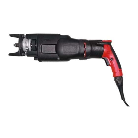
110 V or 230 V. 3.2 THE PARTS OF THE T-35 Main parts: 1. Tube support 2. T-DRILL head, 3. T-DRILL tee forming unit, 4. Power unit , 5. Connecting cord, ¨NOTE! Delivery package includes a bottle of lubricant to be used for... -
Page 10: Information About Accessories
The outlet size range of T-35 is 10 - 35 mm (3/8”–1 3/8”) The diameter of the run tube can be 15 - 76,1mm (5/8”–3”). The maximum wall thickness of the tube to be formed depends on the tube diameter and the size of the T-DRILL head used. -
Page 11: Lubrication
4. TRANSPORT, HANDLING AND STORAGE The T-35 is delivered in a transport box, dimensions 640 mm (25.2”) x 160 mm (6.5”) x 370 mm (14.6”) (w x h x d). Depending on the accessories included, the weight of the box is 13 - 23 kg (29-49 lbs). -
Page 12: Preparations Before Use
INSTRUCTION MANUAL 5. PREPARATIONS BEFORE USE 5.1 T-35, DETACHMENT AND ATTACHMENT OF THE CONNECTING CORD The T-35 power unit is equipped with a connecting cord which allows quick changeovers in field conditions. The European connecting cord The US type connecting cord Detachment of the cord 1. -
Page 13: The Operation Of The Machine
T-35 COLLARING MACHINE 6. THE OPERATION OF THE MACHINE 6.1 DESCRIPTION OF THE CONTROL DEVICES Control devices: 1. Feed mechanism engagement lever for outlet forming, 2. trigger ¨NOTE! Use maximum speed of rotation when drilling and forming the outlet - when working press the trigger completely down! Feed mechanism lever The feed mechanism lever is situated near the chuck ring. -
Page 14: Selection And Adjustment Of The T-Drill Heads
INSTRUCTION MANUAL 6.2 SELECTION AND ADJUSTMENT OF THE T-DRILL HEADS 6.2.1 THE IDENTIFICATION OF THE T-DRILL HEAD The size of the T-DRILL head is stamped on the cover plate: 17.2 3/8” 5050087 Identification: 1. Actual size in millimeters, 2. Nominal size in inches (NS), 3. The ordering... -
Page 15: The Fine Adjustment Of The Outlet Diameter
Check the forming pin span diameter T Depending on the size of the T-DRILL head, the forming pin span T should be 0,5 – 1,4 mm (0.020” – 0.055”) bigger than the branch pipe’s outer diameter (O.D.) To obtain correct joint diameter a fine adjustment is occasionally needed. -
Page 16: Chucking The T-Drill Head
6.3 CHUCKING THE T-DRILL HEAD 6.3.1 CHUCKING To insert the T-DRILL head into the chuck, rotate the locking ring (1) clockwise and slide the T-DRILL head shaft into the chuck. Release the locking ring. Rotate the T-DRILL head (2) in the chuck until it locks. Make sure the T-DRILL head is tightly chucked. -
Page 17: Tee Forming Process With The T-Drill T-35
T-35 COLLARING MACHINE 6.4 TEE FORMING PROCESS WITH THE T-DRILL T-35 Since the process may be new to you, we recommend that you read the following instructions carefully and then practice a few times on some pieces of scrap tubing. - Page 18 This ensures that you obtain a circular outlet. 12. Once the T-DRILL head has come completely out of the outlet, release the trigger. The outlet is now ready. IMPORTANT! Release the drill trigger as soon as the T-DRILL head clears the rim of the outlet.
-
Page 19: Annealing Of Tube
3. Drill a pilot hole into the tube. 4. Start the forming process. ¨NOTE! Always lubricate the T-DRILL head before each work cycle. ¨NOTE! T-DRILL recommends that tubes are annealed whenever the formed outlet is as large as the tube itself. -
Page 20: Maintenance
7. MAINTENANCE 7.1 MACHINE MAINTENANCE The T-DRILL T-35 is prelubricated and does not need special attention for maintenance. Clean dust and dirt from machine surface and power unit vents periodically. ¨NOTE! All other maintenance measures that need to be performed on the T-35 tee-forming machine or the power unit during the warranty period must be carried out by certified TDRILL service agents. -
Page 21: Trouble-Shooting
Burrs in the tee that has been formed Insufficient lubricant during forming of Always lubricate the T-Drill head carefully the outlet. before every outlet forming operation Lubricant not suitable to the material Consult your local T-DRILL representative... -
Page 22: Disposal
T-DRILL must receive a complaint in writing within 10 days after a defect has been noticed and, if T-DRILL so decides, the buyer will have to return the complete tool to the nearest T-DRILL Representative or Distribution Centre. THIS WARRANTY IS PRIMARY. -
Page 23: Supplement
11.1 CAPACITY CHART Use the capacity charts to determine the maximum wall-thickness of the tube and to select the right T-DRILL head. Instructions for the use of the capacity charts: 1. Use the unit of measure that is correct for you: the measures of the charts are in both millimeters and inches. -
Page 24: Notcher Nd-54
INSTRUCTION MANUAL 12. NOTCHER ND-54 12.1 GENERAL 12.1.1 PURPOSE OF THE TOOL The tube end notcher is a device for the preparation of the end of the tube before insertion into the T-branch collar. It cuts a curved notch and produces two dimples simultaneously, one 6mm (1/4”) atop the other. -
Page 25: Description Of Parts
T-35 COLLARING MACHINE 12.1.4 DESCRIPTION OF PARTS See chapter 14. Spare parts list. 12.2 OPERATION INSTRUCTIONS Lay the notcher on an even surface. Line up the appropriate die with the base by rotating the body plate. The appropriate die size should face away from the base for maximum leverage. -
Page 26: How To Replace Upper Die
INSTRUCTION MANUAL 12.3.5 HOW TO REPLACE UPPER DIE Remove upper die assy as above (point 12.3.4). To remove name plate, unscrew the two screws and lift off name plate. Secure tube shaft to vise. Only loosen lock screws of holder pins with 3 mm wrench and remove lock screw of 54 mm (2”) holder pin (this will help to position upper die to the right spot when assembling). -
Page 27: Ordering Spare Parts
T-35 COLLARING MACHINE 13. ORDERING SPARE PARTS When ordering spare parts, please state the following details: - Type code of the machine - Manufacturing code of the machine - The part number - A description of the part - The quantity of the parts required The type code and manufacturing code of the machine are indicated on the nameplate of the machine. - Page 28 INSTRUCTION MANUAL This page is intentionally left blank.
-
Page 29: Spare Parts List
T-35 COLLARING MACHINE 14. SPARE PARTS LIST 14.1 T-35 PIPE COLLARING MACHINE Part No. Complete assembly 5330623 T-35 220-240V Europe 5330625 T-35 110V Japan 5330626 T-35 110V G.B. Pos Part No. Name 5330627 Power unit 220-240V Europe 5330628 Power unit 120V USA... - Page 30 SPARE PARTS LIST 14.2 THE T-35 TEE FORMING UNIT 5330174 Pos Part No. Name 5330174 T-DRILL tee forming unit, complete assembly 5330171 Housing 5330138 Lead screw 5330097 Nut assy complete 5330017 Reduction gear 4330099 Push rod 3330074 Lever 4540068 3330075...
-
Page 31: The T-35 Tee Forming Unit 5330174
T-35 COLLARING MACHINE 14.2 THE T-35 TEE FORMING UNIT 5330174... -
Page 32: T-Drill Collaring Heads
SPARE PARTS LIST 14.3 T-DRILL COLLARING HEADS Tee Size Ø mm Actual Tee Size Ø inch 5/16 ½ ¾ 1 1/8 1 3/8 Order No. 5310408 5310399 5310400 5310401 5310402 5310403 5310404 5310411 5310400 5310408 / 5310398 5310399 5310401 5310402... -
Page 33: Collaring Head 5310408A Ø 8 (5/16") And Pair Of Pins
T-35 COLLARING MACHINE 14.3.1 COLLARING HEAD 5310408A Ø 8 (5/16”) AND PAIR OF PINS Pos. Size / type Part No. Name Standard/manuf. Qty 5310398 Collaring head Ø8 3310235 Forming pin P2 14.3.1.1 COLLARING HEAD 5310398 Ø 8 (5/16”) Pos. Part No. -
Page 34: Collaring Head 5310399B Ø 10 (3/8")
SPARE PARTS LIST 14.3.2 COLLARING HEAD 5310399B Ø 10 (3/8”) Pos. Size / type Part No. Name Standard/manuf. Qty 2310140 Drill core 6,2-2,5 3310468 Forming pin Ø2.5 2310283 Cone 3310293 Adjusting shim 4310323 Cover Ø10, 1/4" 4310372 Screw 4310376 Spring 3310380 Conical cover 14 9019003... -
Page 35: Collaring Head 5310400C Ø 12 (1/2")
T-35 COLLARING MACHINE 14.3.3 COLLARING HEAD 5310400C Ø 12 (1/2”) Pos. Size / type Part No. Name Standard/manuf. Qty 2310150 Drill core 8,0-3 3310469 Forming pin Ø3 2310283 Cone 3310293 Adjusting shim 4310329 Cover Ø12, 3/8" (5310400) 4310372 Screw 4310376... -
Page 36: Collaring Head 5310401 Ø 15 (5/8")
SPARE PARTS LIST 14.3.4 COLLARING HEAD 5310401 Ø 15 (5/8”) Pos. Size / type Part No. Name Standard/manuf. Qty 2310160 Drill core 9,7-4 6310551 Forming pin CrN Ø4,0 2310283 Cone 3310297 Adjusting shim 4310335 Cover Ø15, 1/2" (5310401) 4310372 Screw 4310376 Spring 3310380... -
Page 37: Collaring Head 5310402 C Ø 18 (3/4")
T-35 COLLARING MACHINE 14.3.5 COLLARING HEAD 5310402 C Ø 18 (3/4”) Pos. Size / type Part No. Name Standard/manuf. Qty 2310170 Drill core 10,5-4 6310551 Forming pin CrN Ø4,0 2310283 Cone 3310310 Adjusting shim 4310341 Cover Ø18, 5/8" (5310402) 4310372... -
Page 38: Collaring Head 5310403 C Ø 22 (7/8")
SPARE PARTS LIST 14.3.6 COLLARING HEAD 5310403 C Ø 22 (7/8”) Pos. Size / type Part No. Name Standard/manuf. Qty 2310180 Drill core 12,2-5 4310473 Forming pin P5 2310283 Cone 3310304 Adjusting shim 4310347 Cover Ø22 (5310403) 3310389 Conical cover 20 4310372 Screw 4310376... -
Page 39: Collaring Head 5310404 D Ø 28 (1 1/8")
T-35 COLLARING MACHINE 14.3.7 COLLARING HEAD 5310404 D Ø 28 (1 1/8”) Pos. Size / type Part No. Name Standard/manuf. Qty 2310210 Drill core 18,0-6 4310474 Forming pin CrN pinnoite 2310283 Cone 3310304 Adjusting shim 4310359 Cover Ø28, 1" (5310404) -
Page 40: Collaring Head 5310411 Ø 35 (1 3/8")
SPARE PARTS LIST 14.3.8 COLLARING HEAD 5310411 Ø 35 (1 3/8”) Pos. Size / type Part No. Name Standard/manuf. Qty 4310221 Drill core 22,0-8 3430033 Forming pin Ø8 B 4310362 Cover 35, 1 1/4" (5310411) 4310372 Screw 2310451 Cone 4310376 Spring 3050149 Conical cover... -
Page 41: Optional Equipment
T-35 COLLARING MACHINE 14.4 OPTIONAL EQUIPMENT Part No. Name Size, standard, manufacturer 5090294 Notcher ND-54 9010205 Bottle of lubrication... -
Page 42: Notcher Nd-54 5090294
SPARE PARTS LIST 14.5 NOTCHER ND-54 5090294 Pos Part No. Name 4090275 Base 2090276 Body plate 2090277 Lower die 6090304 Upper die 6090305 Support plate for upper die 6090303 Holder pin plate 4090298 4090281 Tube shaft 3090282 Screw rod 3090293 Lever 4090094 Spacer roll... - Page 43 T-35 COLLARING MACHINE 14.5 NOTCHER ND-54 5090294...
- Page 44 Address: Ampujantie 32 FIN-66400 LAIHIA FINLAND Name of the person authorized to compile the technical file: Juha Murtomäki confirms that machine T-DRILL T-35 putkenkaulustuskone 3311 (Pipe collaring machine) (Make) (Type code ) Complies with the regulations of the following other EU directives:...
- Page 45 Product Name: MOBILMET 763 Revision Date: 05Sep2007 Page 1 of 9 ______________________________________________________________________________________________________________________ MATERIAL SAFETY DATA SHEET SECTION 1 PRODUCT AND COMPANY IDENTIFICATION PRODUCT Product Name: MOBILMET 763 Product Description: Base Oil and Additives Product Code: 663492-00, 971506 Intended Use: Metal processing fluid COMPANY IDENTIFICATION Supplier: EXXON MOBIL CORPORATION...
- Page 46 Product Name: MOBILMET 763 Revision Date: 05Sep2007 Page 2 of 9 ______________________________________________________________________________________________________________________ SECTION 4 FIRST AID MEASURES INHALATION Remove from further exposure. For those providing assistance, avoid exposure to yourself or others. Use adequate respiratory protection. If respiratory irritation, dizziness, nausea, or unconsciousness occurs, seek immediate medical assistance.
- Page 47 Product Name: MOBILMET 763 Revision Date: 05Sep2007 Page 3 of 9 ______________________________________________________________________________________________________________________ In the event of a spill or accidental release, notify relevant authorities in accordance with all applicable regulations. In the event of a spill or accidental release, notify relevant authorities in accordance with all applicable regulations.
- Page 48 Product Name: MOBILMET 763 Revision Date: 05Sep2007 Page 4 of 9 ______________________________________________________________________________________________________________________ PERSONAL PROTECTION Personal protective equipment selections vary based on potential exposure conditions such as applications, handling practices, concentration and ventilation. Information on the selection of protective equipment for use with this material, as provided below, is based upon intended, normal usage.
- Page 49 Product Name: MOBILMET 763 Revision Date: 05Sep2007 Page 5 of 9 ______________________________________________________________________________________________________________________ Relative Density (at 15 C ): 0.87 Flash Point [Method]: >160C (320F) [ ASTM D-92] Flammable Limits (Approximate volume % in air): LEL: 0.9 UEL: 7.0 Autoignition Temperature: N/D Boiling Point / Range: >...
- Page 50 Product Name: MOBILMET 763 Revision Date: 05Sep2007 Page 6 of 9 ______________________________________________________________________________________________________________________ Irritation (Rabbit): Data available. May cause mild, short-lasting discomfort to eyes. Based on test data for structurally similar materials. CHRONIC/OTHER EFFECTS For the product itself: Oil Mist (highly refined oils): Animals exposed to high concentrations of mist developed oil retention, inflammation, and oil granulomas in the respiratory tract.
- Page 51 Product Name: MOBILMET 763 Revision Date: 05Sep2007 Page 7 of 9 ______________________________________________________________________________________________________________________ REGULATORY DISPOSAL INFORMATION RCRA Information: The unused product, in our opinion, is not specifically listed by the EPA as a hazardous waste (40 CFR, Part 261D), nor is it formulated to contain materials which are listed as hazardous wastes. It does not exhibit the hazardous characteristics of ignitability, corrositivity or reactivity and is not formulated with contaminants as determined by the Toxicity Characteristic Leaching Procedure (TCLP).
- Page 52 Product Name: MOBILMET 763 Revision Date: 05Sep2007 Page 8 of 9 ______________________________________________________________________________________________________________________ 5 = TSCA 4 10 = CA P65 CARC 15 = MI 293 Code key: CARC=Carcinogen; REPRO=Reproductive SECTION 16 OTHER INFORMATION N/D = Not determined, N/A = Not applicable THIS SAFETY DATA SHEET CONTAINS THE FOLLOWING REVISIONS: Revision Changes: Section 13: Empty Container Warning was modified.
- Page 53 More T-DRILL products for cutting and collaring HFT-2000 T-65 SS Semiautomatic unit for small volume production of Tube Collaring System for stainless steel pipes T-DRILL collars. -Collar sizes 20-51mm -Collar sizes 10-54 mm -Run tube sizes 32 - 219.1 mm...
Need help?
Do you have a question about the T-35 and is the answer not in the manual?
Questions and answers